
 with MyoWare Muscle Sensor & Arduino")
Overview
In this project, we will interface the MyoWare Muscle Sensor with Arduino & make our own Electromyography Device. Electromyography (EMG) is an electrodiagnostic medicine technique for evaluating and recording the electrical activity produced by skeletal muscles. EMG is performed using an instrument called an electromyograph to produce a record called an electromyogram.
Most of the standard EMG measurement systems are expensive and not feasible for personal applications. For personal hobbyists like me, the MyoWare Muscle Sensor offers a good starting point for learning about the Muscular Movement or Electromyography. The Myoware Muscle Sensor just costs lesser than 40$. Besides the main sensor board, there is also a complete development kit that costs almost 80$ with more accompanying components for researchers & Beginners.
Apart from Electromyography, earlier we learned about the Electrocardiogram using the AD8232 ECG Sensor & Arduino. We studied the electrical activity of the Heart. Here we will study the electrical activity of the muscles. So for that, we will make our own Electromyograph using MyoWare Muscle Sensor & Arduino.
Bill of Materials
All the components used for studying EMG Signal can be purchased easily from the following Amazon link.
| S.N. | Components Name | Quantity | Purchase Links |
|---|---|---|---|
| 1 | Arduino Nano Board | 1 | Amazon | AliExpress |
| 2 | MyoWare Muscle Sensor Kit | 1 | Amazon | AliExpress |
| 3 | 0.96" I2C OLED Display | 1 | Amazon | AliExpress |
| 4 | 5V DC Power Supply | 1 | Amazon | AliExpress |
| 5 | Connecting Wires | 10 | Amazon | AliExpress |
| 6 | Breadboard | 1 | Amazon | AliExpress |
Electromyography(EMG)
Electromyography (EMG) is a diagnostic procedure that evaluates the health condition of muscles and the nerve cells that control them. These nerve cells are known as motor neurons. They transmit electrical signals that cause muscles to contract and relax. An EMG translates these signals into graphs or numbers, helping doctors to make a diagnosis.
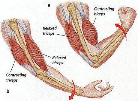
The electrical activity picked up by the electrodes is displayed on an oscilloscope. An audio-amplifier is used so the activity can be heard. EMG measures the electrical activity of muscle during rest, slight contraction, and forceful contraction. Muscle tissue does not normally produce electrical signals during rest. When an electrode is placed, a brief period of activity can be seen on the oscilloscope.

How EMG is measured?
Surface EMG assesses muscle function by recording muscle activity from the surface above the muscle on the skin. Surface electrodes are able to provide only a limited assessment of muscle activity. Surface EMG can be recorded by a pair of electrodes or by a more complex array of multiple electrodes. More than one electrode is needed because EMG recordings display the potential difference between two separate electrodes.

Medical Uses of EMG
EMG testing has a variety of clinical and biomedical applications
1. EMG is used as a diagnostics tool for identifying neuromuscular diseases
2. EMG is used as a research tool for studying kinesiology
3. To find out the disorders of motor control
4. EMG signals are sometimes used to guide botulinum toxin or phenol injections into muscles
5. EMG is performed with another electrodiagnostic medicine test that measures the conducting function of nerves
6. EMG signals are also used as a control signal for prosthetic devices such as prosthetic hands, arms & lower limbs
MyoWare Muscle Sensor

The MyoWare Muscle Sensor is an all-in-one electromyography (EMG) sensor from Advancer Technologies. The MyoWare board acts by measuring the filtered and rectified electrical activity of a muscle. It gives the output from 0 to Vin Volts depending on the amount of activity in the selected muscle. The sensor is easy to use. You need to stick on a few electrodes & read the voltage out when muscles are flexed.
The sensor has a wearable design that allows you to attach biomedical sensor pads directly to the board. This board includes a single-supply voltage of +3.1V to +5V, RAW EMG output, polarity protected power pins, indicator LEDs, and an On/Off switch. Additionally, it has a few shields like Cable, Power & Proto that can attach to the Myoware Muscle Sensor to help increase its versatility and functionality!

You can interface the MyoWare Muscle Sensor with Arduino or any other microcontrollers easily. The result obtained after bending the muscle can be observed in Serial Monitor as a numerical value or on Serial Plotter as a graphical format.
MyoWare Muscle Sensor Kit

1. Embedded Electrode Connectors:
The embedded electrode connectors allow you to stick the board right to the target muscle and avoid the hassle of wires.
2. Cable Shield:
There may still be cases where you want to mount the sensor pads away from the other hardware. For these cases, the MyoWare Cable Shield is used.
3. Electrode Cable:
Instead of attaching the sensor pads directly to the MyoWare Muscle Sensor, they can be attached to the shield’s 3.5mm TRS jack connector. Both sets of contacts will be connected together, so make sure to only use one pad for each reference [R], end [E], and middle [M] pin.
4. Power Shield:
The MyoWare Power Shield is designed to take two coin cell batteries such as some standard CR2032s. They are connected in parallel for extended capacity at a nominal 3.0V.
5. Proto Shield:
The MyoWare Proto Shield passes all signals to a bit of protoboard. Use this area to solder on whatever custom circuitry you can come up with.
6. LED Shield:
For those users looking for a large display of the signal level, we offer the MyoWare LED Shield.
Interfacing MyoWare Muscle Sensor with Arduino
Now let us interface the Myoware Muscle Sensor with the Arduino. The connection diagram is given below.

Connect the Sensor VCC to 5V of Arduino & GND to GND. Similarly, connect the analog pin to A0 of Arduino since we are measuring the analog voltage.
Source Code/Program
The program for Interfacing Myoware EMG muscle sensor with Arduino is very simple. All we need is the measurement of Analog Voltage.
|
1 2 3 4 5 6 7 8 9 10 11 12 13 14 15 16 17 18 19 |
void setup() { Serial.begin(9600); } void loop() { float sensorValue = analogRead(A1); float millivolt = (sensorValue/1023)*5; Serial.print("Sensor Value: "); Serial.println(sensorValue); Serial.print("Voltage: "); Serial.print(millivolt*1000); Serial.println(" mV"); Serial.println(""); delay(1); } |
Steps to be followed to use Myoware Muscle Sensor
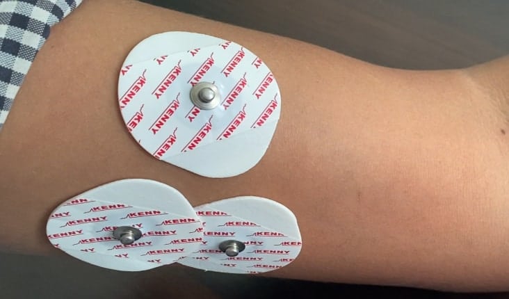
- Fist thoroughly clean the intended area with soap to remove dirt and oil.

-
Snap electrodes to the sensor’s snap connectors
-
Peel off the backs of the electrodes to expose the adhesive and apply them to the skin.

-
Place the sensor on the desired muscle. Place the sensor so one of the connected electrodes is in the middle of the muscle body. The other electrode should line up in the direction of the muscle length.

-
Place the reference electrode on a bony or nonadjacent muscular part of your body near the targeted muscle.
-
Connect the sensor to the Arduino Board as per the circuit diagram.


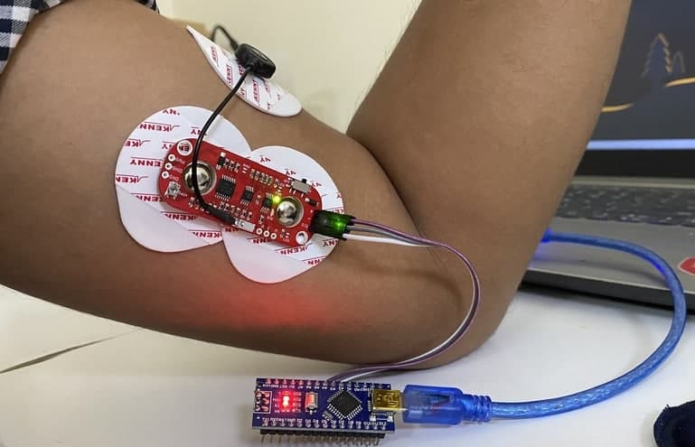
You can either connect the Embedded Electrode Connectors directly to the muscles as shown above. Or you can use the cable shield along with the cable connectors directly as shown below.

The extension shield has a long cable which helps in placing the sensor far away from the computer.

Testing & Results: Electromyography
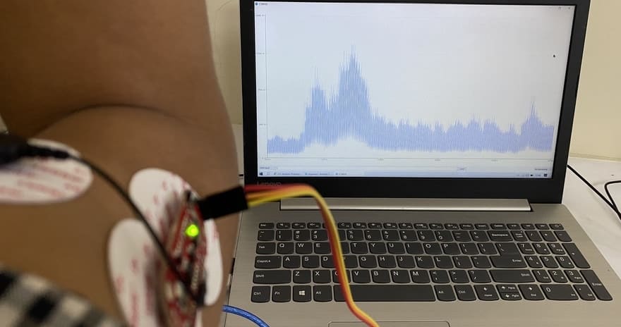
After uploading the code, you can start testing the sensor and start observing the value. To test the sensor working, stretch your arm. Then you can contract or relax the muscle. This will produce an analog voltage, that can be observed on Serial Monitor.
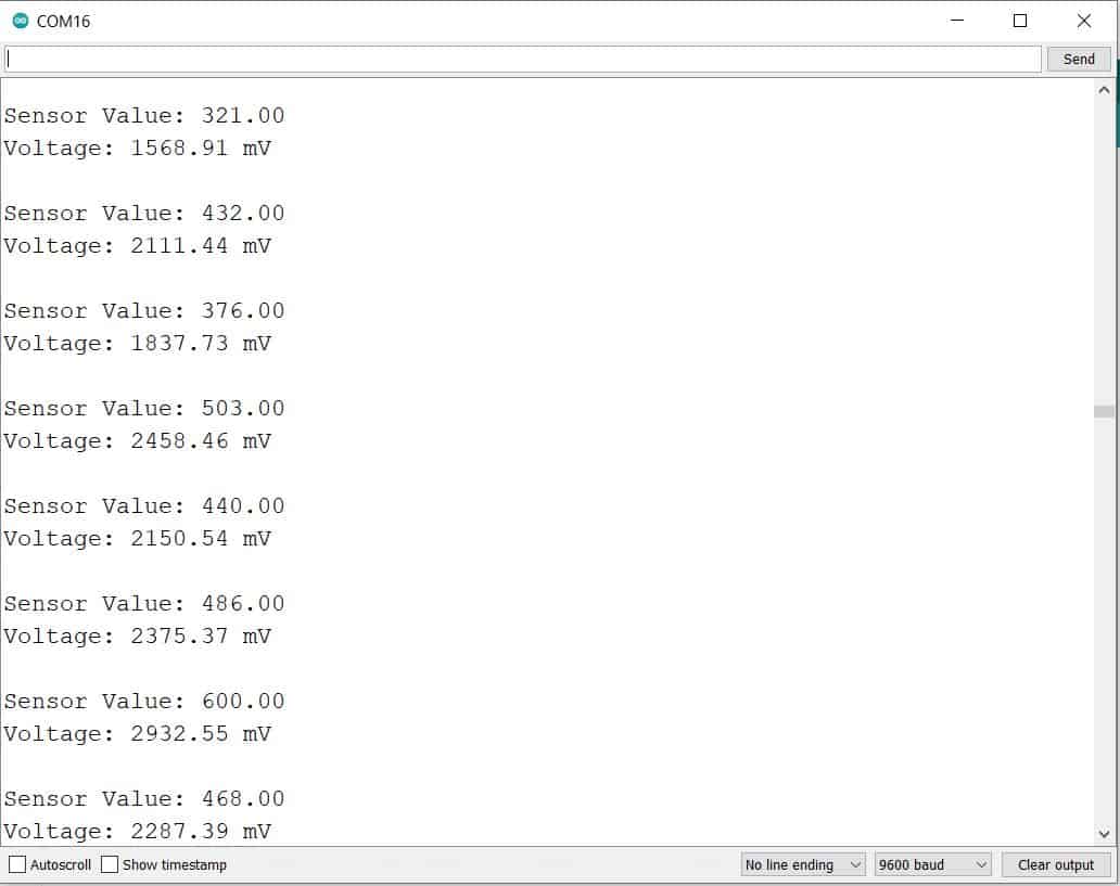
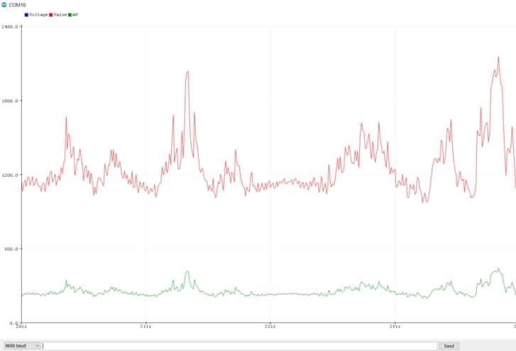
The waveform can be observed on Serial Plotter as well. To do so, open the serial plotter screen and see the waveform when the arm is brought into movement.
Reading EMG Data of OLED Display
Apart from the above observations, if you want to read the sensor data or analog voltage on OLED Display, you can use the following code. But before that OLED Display with the Arduino Board. Connect the I2C Pins (SDA & SCL) of OLED Display to A4 & A5 of Arduino.

Source Code/Program
|
1 2 3 4 5 6 7 8 9 10 11 12 13 14 15 16 17 18 19 20 21 22 23 24 25 26 27 28 29 30 31 32 33 34 35 36 37 38 39 40 41 42 43 44 45 46 47 48 49 50 51 52 53 54 55 56 57 58 59 60 |
#include <Wire.h> #include <Adafruit_GFX.h> #include <Adafruit_SSD1306.h> #define SCREEN_WIDTH 128 // OLED display width, in pixels #define SCREEN_HEIGHT 64 // OLED display height, in pixels #define OLED_RESET -1 // Reset pin # (or -1 if sharing Arduino reset pin) Adafruit_SSD1306 display(SCREEN_WIDTH, SCREEN_HEIGHT, &Wire, OLED_RESET); void setup() { Serial.begin(9600); display.begin(SSD1306_SWITCHCAPVCC, 0x3C); //initialize with the I2C addr 0x3C (128x64) delay(500); display.clearDisplay(); display.setCursor(30, 15); display.setTextSize(1); display.setTextColor(WHITE); display.println("Sensor"); display.setCursor(25, 35); display.setTextSize(1); display.print("Initializing"); display.display(); delay(3000); } void loop() { float sensorValue = analogRead(A1); float millivolt = (sensorValue/1023)*5; Serial.print("Sensor Value: "); Serial.println(sensorValue); Serial.print("Voltage: "); Serial.print(millivolt*1000); Serial.println(" mV"); Serial.println(""); display.clearDisplay(); display.setTextSize(1); display.setCursor(0, 0); display.print("Sensor Value: "); display.setTextSize(2); display.setCursor(0, 10); display.println(sensorValue,0); display.setTextSize(1); display.setCursor(0, 35); display.print("Voltage: "); display.setTextSize(2); display.setCursor(0, 45); display.print(millivolt*1000); display.println(" mv"); display.display(); delay(1); } |
Upload the above code and when done, the OLED Display will start displaying the value of EMG Analog Signal as well as voltage.

Video Tutorial & Guide


")


9 Comments
Hello! I don’t understand why do you divide the sensor value per 1023 and then multiple by 5. Can you help me ? please
The controller is a 10 bit controller which means values ranges from 0-1023 as 10bit=2^10. The 1023 is also equal to 5V. So we are calculating the voltage output using mathematical equation.
Give abstract for this
Hello, are the jumper cables you used in the project male-male?
Hello, is there any way to export the graph as a png, jpg, pdf or something like that?
Hello, I have a question about the first code you wrote. Is the unit of the output voltage correct? And can you explain me about how the units derived as millivolt?
i did the same setup, but i keep getting unstable values in the serial monitor (doesn’t matter whether i flex or relax my hand, the numbers are the same), could you please help?
Those are basically analog amplifiers which perform only basic filtering and they are sensitive to many things – getting a stable output is not that simple: noise is introduced via signal wires, via power supply, and via various cables around.
What could help in your case:
1. switch laptop to battery power, disconnect it from mains
2. make sure there are no mains cables or large metal surfaces close to you
3. make sure skin contact is reliable, right over your muscle, and electrodes are fresh (even if you use them 2nd time they already would work much worse, 3rd time and more they won’t be suitable at all – you need a lot of spare electrodes to work with such sensors)
Alternative solution is to use wireless sensors with dry electrodes – one example is uMyo
Is there a way to use a button to pause the data? What type of button would work best? I am having no luck