

Overview
In this IoT project, we will learn how to make an IoT-based Home Automation project using ESP32 and the new Blynk 2.0 IoT app to control a 4-channel relay module from the manual switch & smartphone. The project has Real-Time Feedback System. We can use the Blynk IoT app from anywhere in the world & using Internet Connectivity we can monitor the real-time feedback in Blynk 2.0 IoT App or Blynk cloud web dashboard.
This tutorial is all about Controlling Peripherals like AC Appliances or bulbs via Relay from Blynk 2.0 IoT App or Blynk cloud web dashboard using ESP32 WiFi Module. We would basically call it a Home Automation Project. Home automation is the automatic control of electronic devices in your home. These devices are connected to the Internet, which allows them to be controlled remotely. Earlier we made so many Home Automation projects which are as follows:
- Home Automation with Arduino IoT Cloud & ESP32
- Home Automation using Google Firebase & ESP8266
- Home Automation using Blynk & ESP8266
- Home Automation using ESP8266 WebServer
- Home Automation using Android & ESP8266
- Home Automation using ESP8266 & Alexa
- Home Automation using ESP32 & AWS IoT Core
- Home Automation using ESP32 & Alexa
- Home Automation using ESP32 WebServer
Bill of Materials
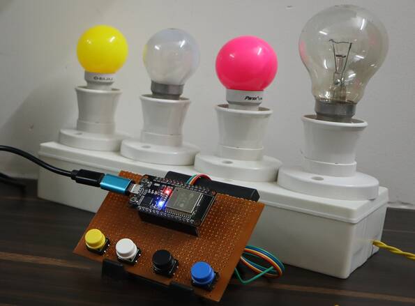
For this project, we will need an ESP32 Board, 4 channel relay, and a few jumper wires. For the demo, we can use 4 bulbs with 4 holders or any other electrical appliances.
All the components can be easily purchased from Amazon through the below Amazon purchase links.
| S.N. | Components | Quantity | Purchase Links |
|---|---|---|---|
| 1 | ESP32 WiFi Module | 1 | Amazon | AliExpress |
| 2 | 5V Relay | 4 | Amazon | AliExpress |
| 3 | Push Button Switches | 4 | Amazon | AliExpress |
| 4 | 7805 Voltage Regulator IC | 1 | Amazon | AliExpress |
| 5 | DC Power Jack DCJ0202 | 1 | Amazon | AliExpress |
| 6 | Diode 1N4007 | 4 | Amazon | AliExpress |
| 7 | Resistor 330-ohm | 5 | Amazon | AliExpress |
| 8 | NPN Transistor BC547 | 4 | Amazon | AliExpress |
| 9 | Terminal Block 5mm | 4 | Amazon | AliExpress |
| 10 | LED 5mm Any Color | 1 | Amazon | AliExpress |
| 11 | Female Header | 2 Set | Amazon | AliExpress |
Circuit Diagram & Hardware
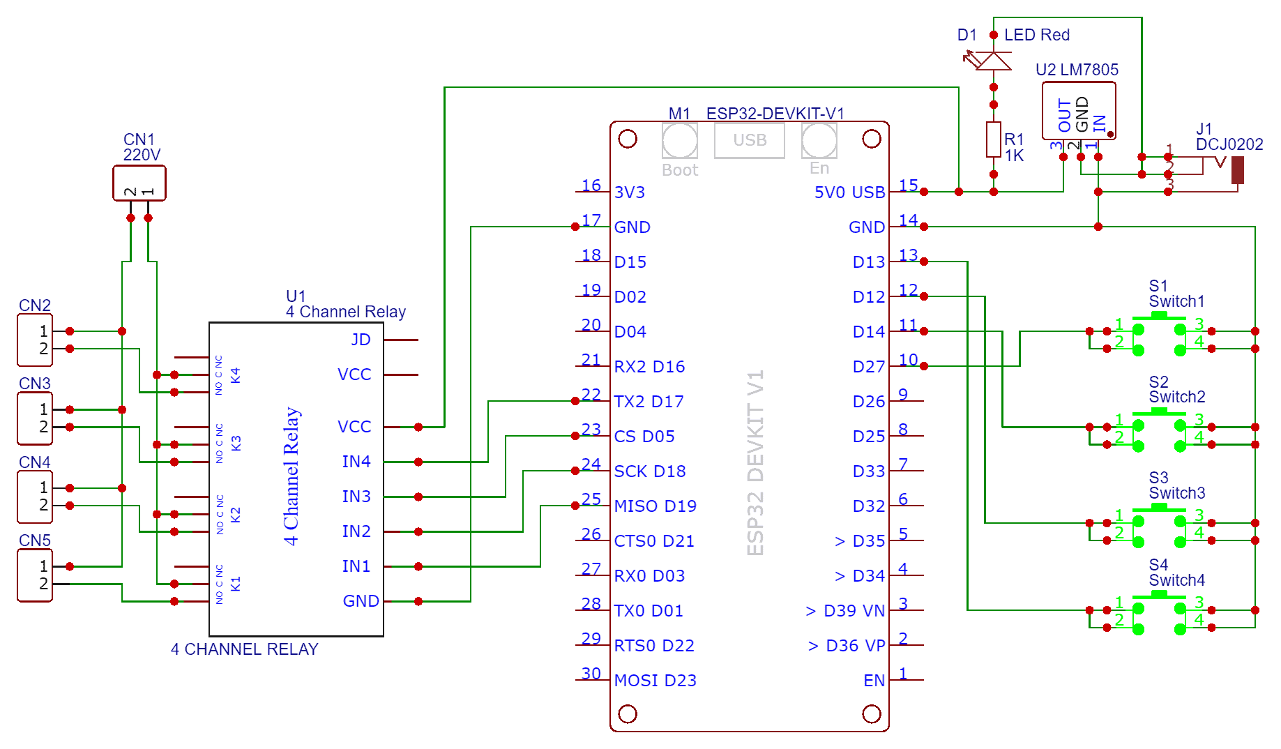
The circuit for Home Automation using Blynk 2.0 & ESP32 with Real-Time Feedback is very simple. I used Fritzing software to draw the schematic. The below circuit diagram is the circuit that you need to Assemble.

The ESP32 Board has so many GPIOs Pins. In this project, we will be using GPIO19, GPIO18, GPIO5 & GPIO17 for controlling the Relay. Across the output of the relay, we will use bulbs for testing and demo. You can use a 9V DC Adapter to power the circuit as the output of 7805 Voltage Regulator IC connects to Vin of ESP32.
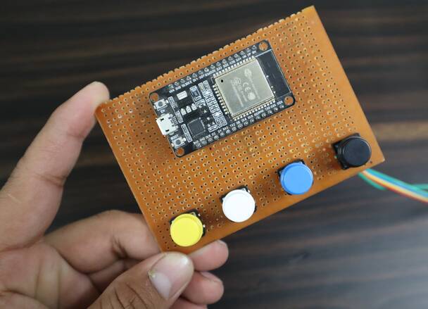
As a feedback system, there are 4 button switches connected directly to the ESP32 GPIO Pins. The ESP32 Pins used are GPIO27, GPIO14, GPIO12 & GPIO13.
Project PCB Gerber File & PCB Ordering Online
If you don’t want to assemble the circuit on a breadboard and you want PCB for the project, then here is the PCB for you. I used EasyEDA to design the Schematic & PCB. The Schematic & PCB Board for ESP32 Home Automation using Blynk 2.0 looks something like the below.
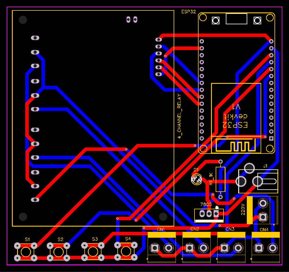
The Gerber File for the PCB is given below. You can simply download the Gerber File and order the PCB from ALLPCB at 1$ only.
You can use this Gerber file to order high quality PCB for this project. To do that visit the ALLPCB official website by clicking here: https://www.allpcb.com/.

You can now upload the Gerber File by choosing the Quote Now option. From these options, you can choose the Material Type, Dimensions, Quantity, Thickness, Solder Mask Color and other required parameters.

After filling all details, select your country and shipping method. Finally you can place the order.
Blynk 2.0 Web & Mobile Dashboard Setup
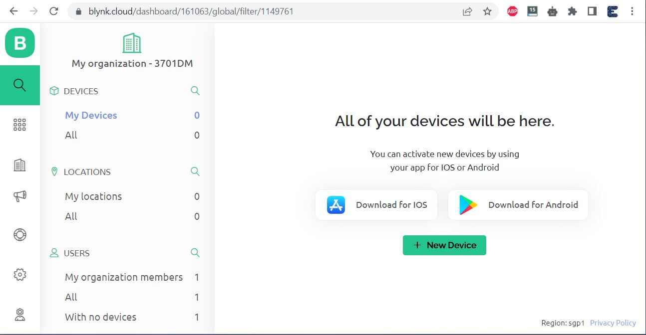
Now let’s set up the Blynk Web Dashboard first. To do that visit blynk.io and sign up using the email ID.
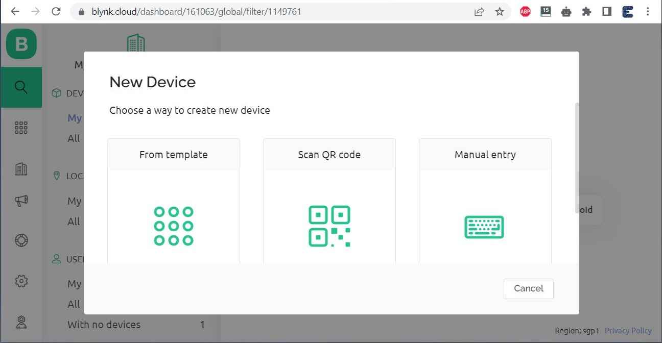
First Add a New Device.
Select the first option, i.e. From Template.
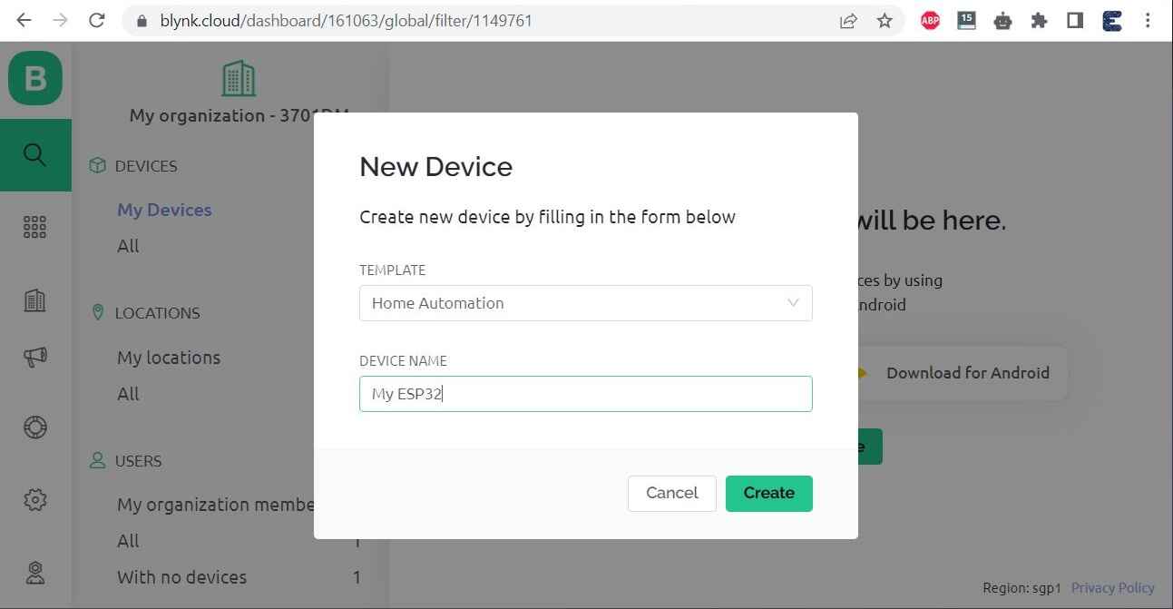
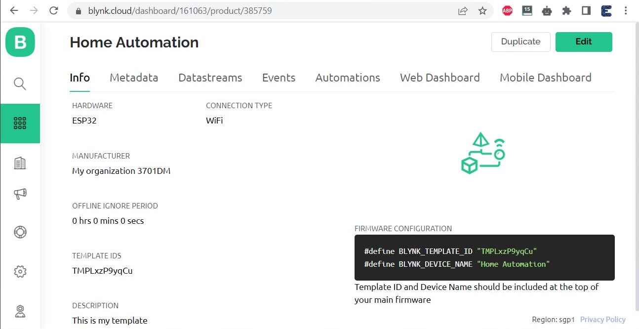
Give Any Name to Template and Device and Click on Create.
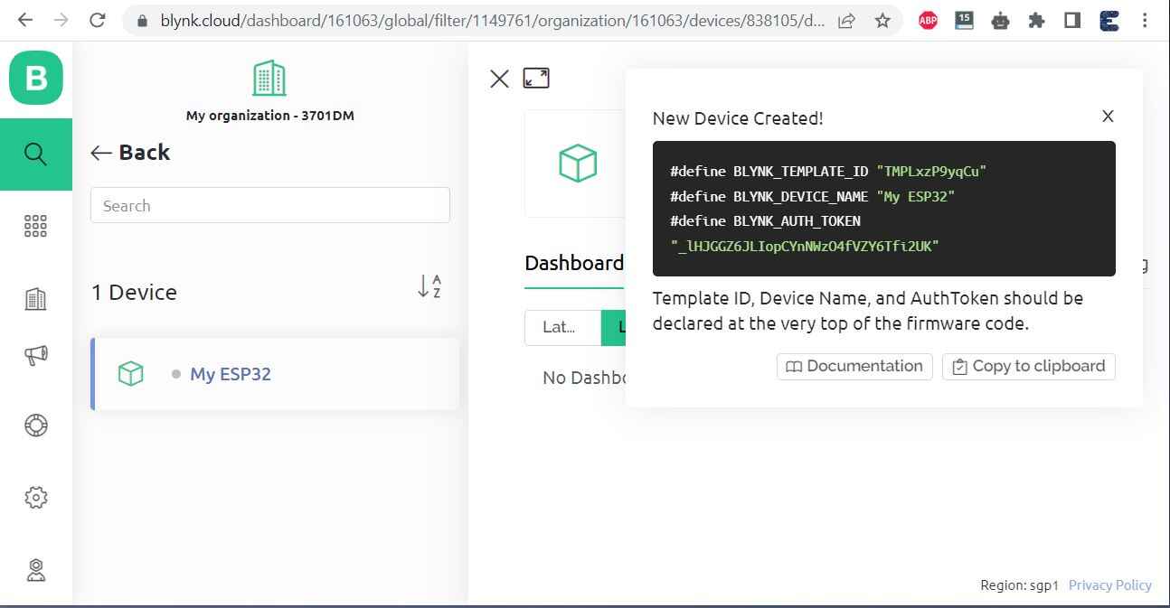
A New Device will be created. A snip of the code header file will appear on the Dashboard. Copy and save this code as it will be used in the Arduino IDE.
Click on the Template logo and select the Template that you just created.
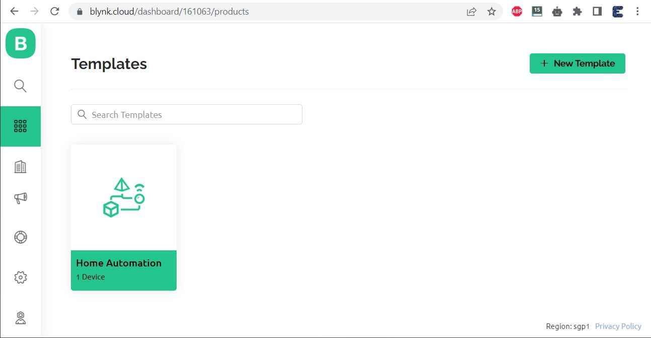
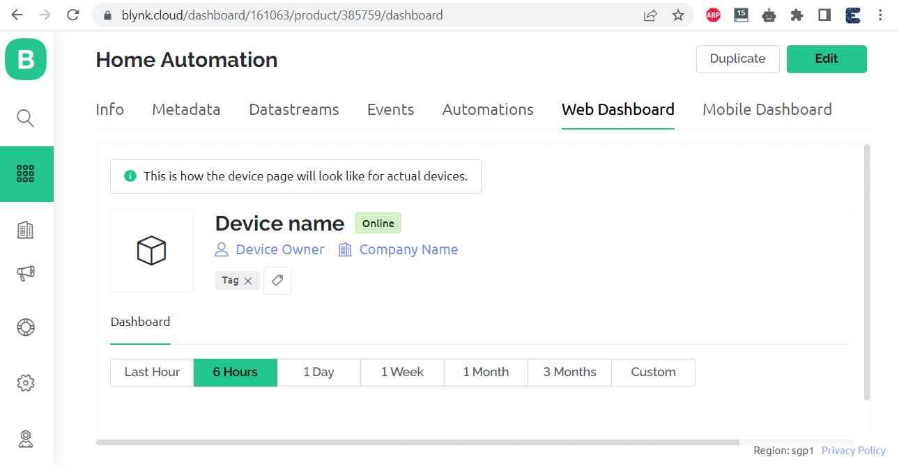
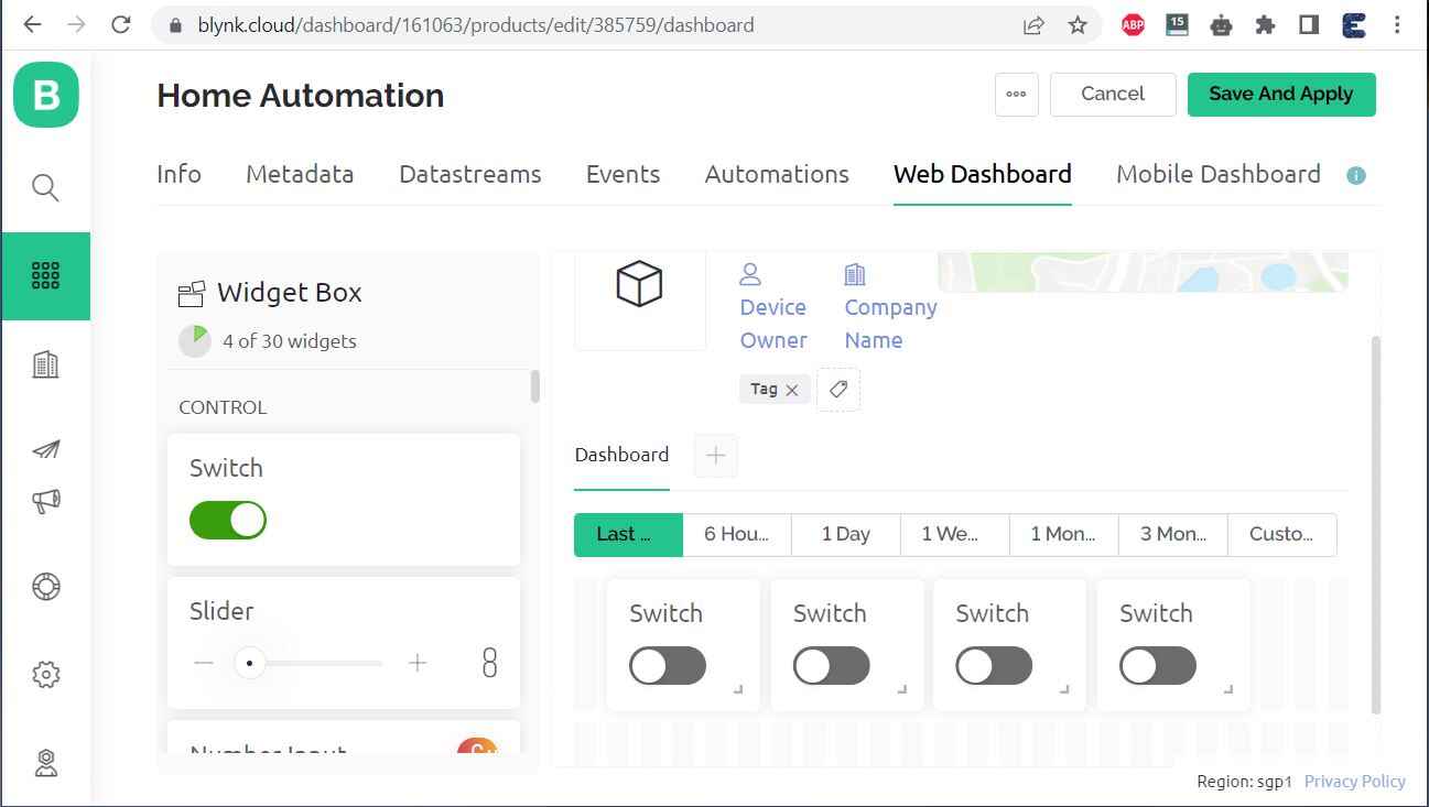
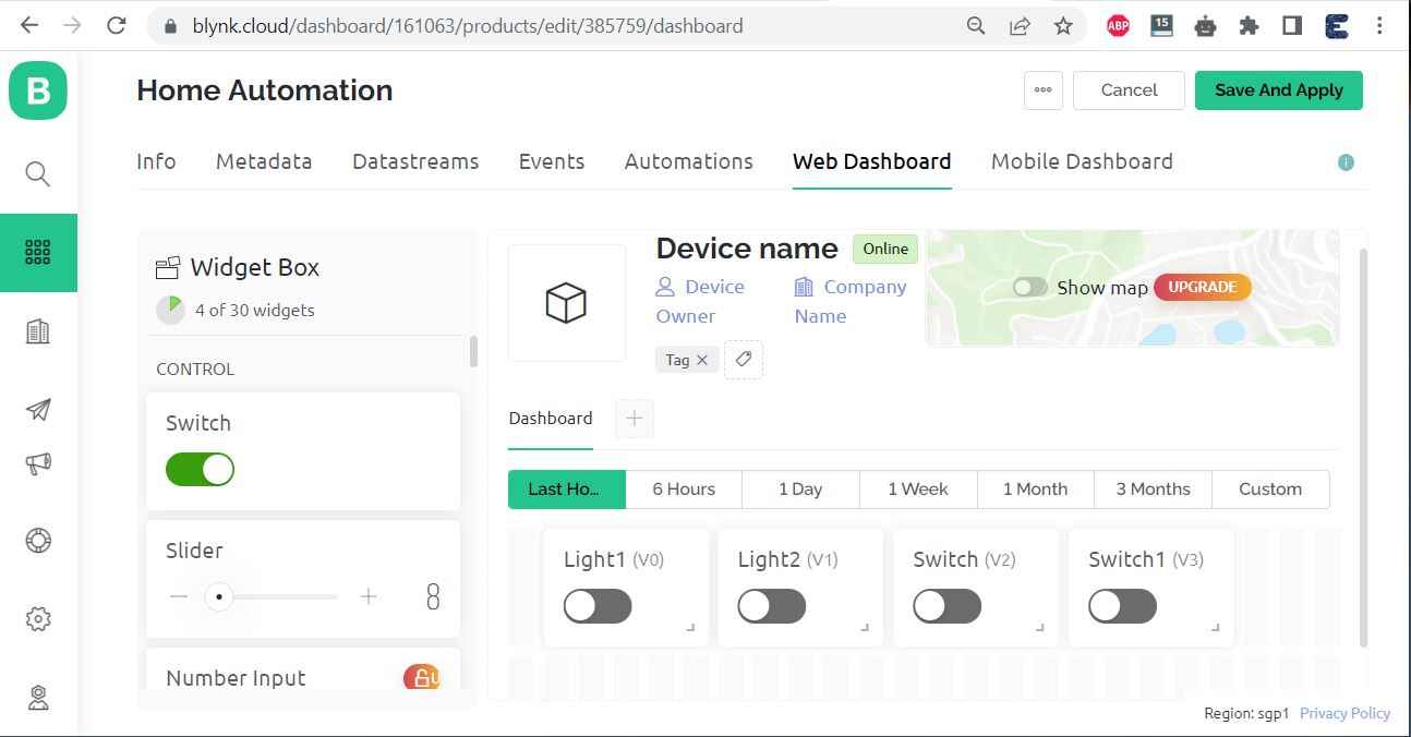
A template page will open. From this template Select the Web Dashboard.
From this page click on edit. Now we need to add the widget to the Dashboard.
Drag the widget called Switch from the left side and place it on the dashboard.
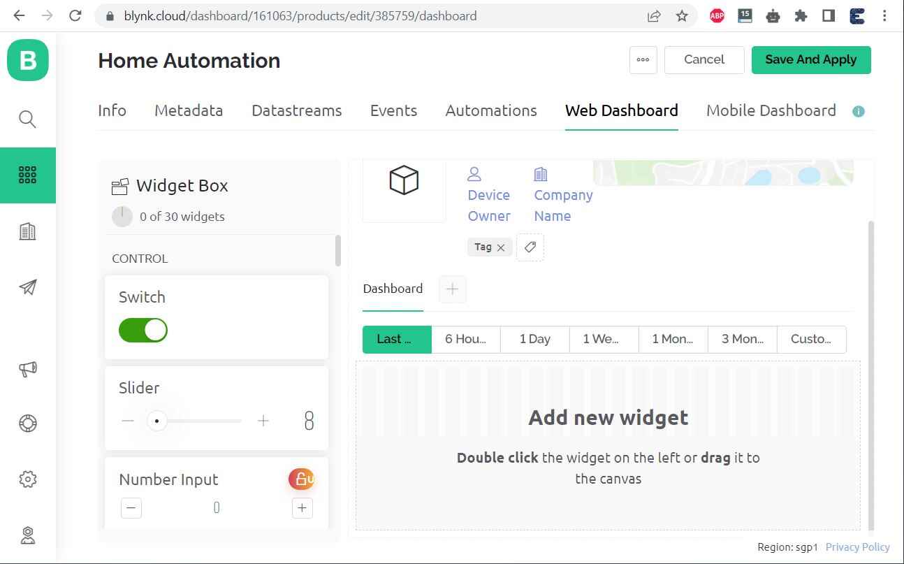
Create such 4 widgets as we have 4 relays to control.
Click on Setting Icon on Widget 1. The following page will open.
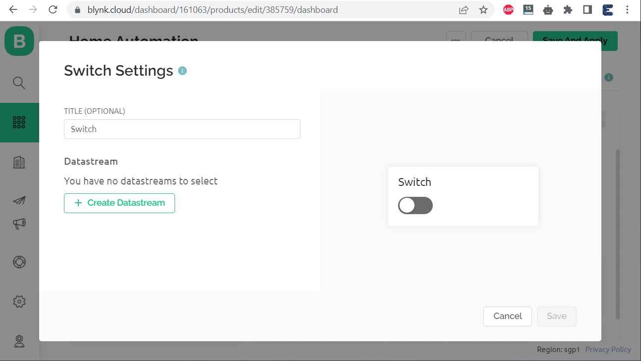
Give Title Name anything. For example Light1 or Realy1. And under the Datastream part, select Virtual Pin.
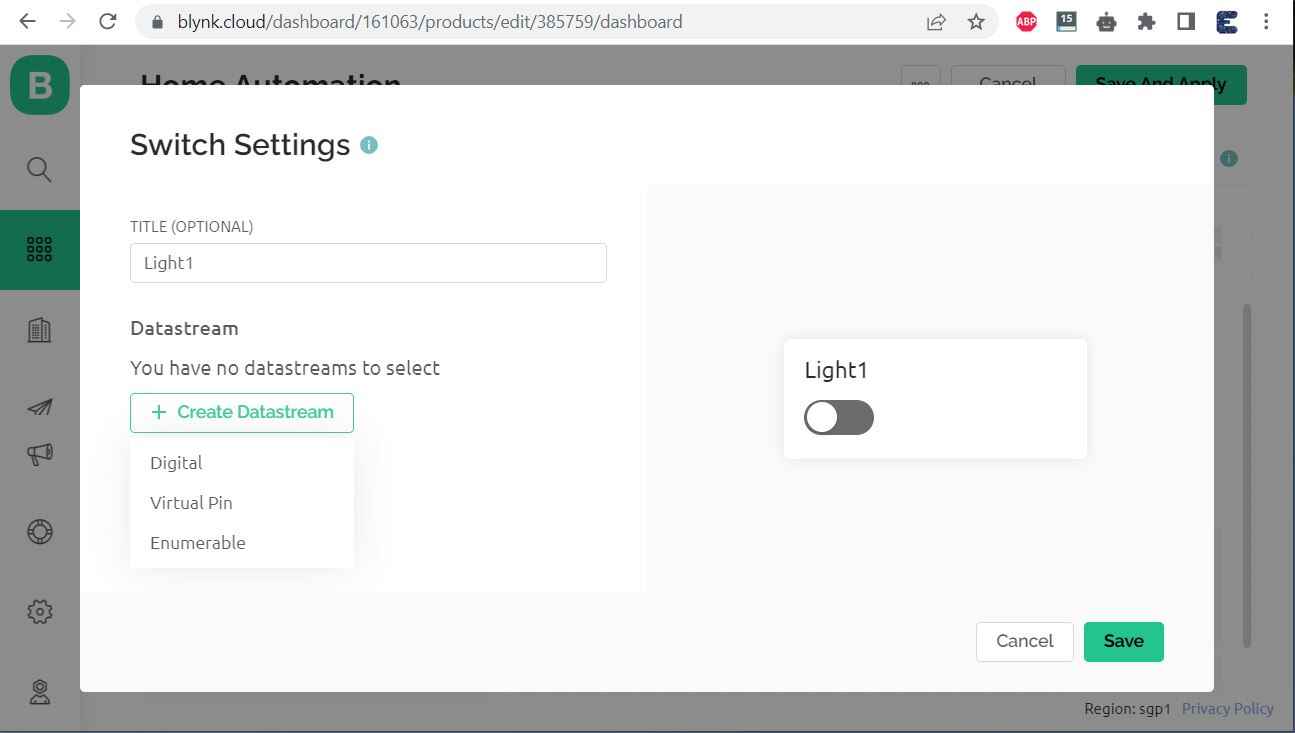
Under Datastream Section, Select Virtual Pin V0. Then Click on Create and then on Save.
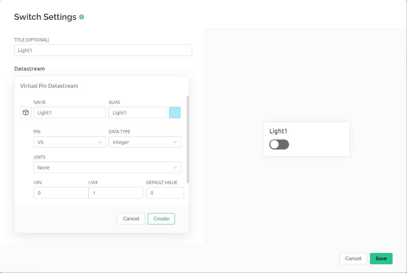
Similarly, do the same for the remaining 3 widgets. Give them the names Light2, Light3, and Light4, and Select Virtual Pin as V1, V2, and V3 respectively. Click on Save and Apply to make changes to what setup has been made so far.
Now your Web Dashboard is Finally Ready.
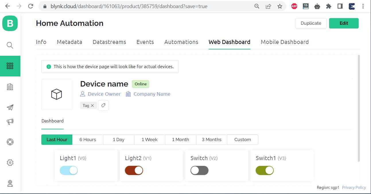
Using this Web Dashboard, you can control your Home Appliances.
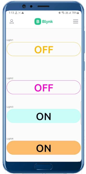
Apart from the Web Dashboard, you can also set up your Mobile App Dashboard. For that download the Blynk from Playstore or AppStore. And you can follow the video below to set up the Dashboard. The Mobile App Dashboard looks something like this.
Code/Program: ESP32 Blynk 2.0 Home Automation with Feedback
The source code or program for Home Automation using ESP32 & Blynk 2.0 with Real-Time Feedback System is written in Arduino IDE.
1. Blynk Library: https://github.com/blynkkk/blynk-library
2. AceButton Library: https://github.com/bxparks/AceButton
Now copy the following code and paste it on your Arduino IDE Sketch. But before that, you need to make modifications to the following lines.
|
1 2 3 |
#define BLYNK_TEMPLATE_ID "TMPLiEm_ytX0" #define BLYNK_DEVICE_NAME "APP" #define BLYNK_AUTH_TOKEN "a16wQs9JID48MryB6TdLaONpFgRw5ymo" |
You can get these details from the Web Dashboard Setup.
Apart from these, modify the WiFi SSID and Password from the following lines.
|
1 2 |
char ssid[] = "*****************"; char pass[] = "*****************"; |
Now copy the following code and upload it to the ESP32 Board.
|
1 2 3 4 5 6 7 8 9 10 11 12 13 14 15 16 17 18 19 20 21 22 23 24 25 26 27 28 29 30 31 32 33 34 35 36 37 38 39 40 41 42 43 44 45 46 47 48 49 50 51 52 53 54 55 56 57 58 59 60 61 62 63 64 65 66 67 68 69 70 71 72 73 74 75 76 77 78 79 80 81 82 83 84 85 86 87 88 89 90 91 92 93 94 95 96 97 98 99 100 101 102 103 104 105 106 107 108 109 110 111 112 113 114 115 116 117 118 119 120 121 122 123 124 125 126 127 128 129 130 131 132 133 134 135 136 137 138 139 140 141 142 143 144 145 146 147 148 149 150 151 152 153 154 155 156 157 158 159 160 161 162 163 164 165 166 167 168 169 170 171 172 173 174 175 176 177 178 179 180 181 182 183 184 185 186 187 188 189 190 191 192 193 194 195 196 197 198 199 200 201 202 203 204 205 206 207 208 209 210 211 212 213 214 215 216 217 218 219 220 221 222 223 224 225 226 227 228 229 230 231 232 233 234 235 236 237 238 239 240 |
#define BLYNK_TEMPLATE_ID "TMPLiEm_ytX0" #define BLYNK_DEVICE_NAME "APP" #define BLYNK_AUTH_TOKEN "a16wQs9JID48MryB6TdLaONpFgRw5ymo" // Your WiFi credentials. // Set password to "" for open networks. char ssid[] = "*****************"; char pass[] = "*****************"; bool fetch_blynk_state = true; //true or false //#define BLYNK_PRINT Serial #include <WiFi.h> #include <WiFiClient.h> #include <BlynkSimpleEsp32.h> #include <AceButton.h> using namespace ace_button; // define the GPIO connected with Relays and switches #define RelayPin1 19 //D19 #define RelayPin2 18 //D18 #define RelayPin3 5 //D5 #define RelayPin4 17 //D17 #define SwitchPin1 27 //D27 #define SwitchPin2 14 //D14 #define SwitchPin3 12 //D12 #define SwitchPin4 13 //D13 #define wifiLed 2 //D2 //Change the virtual pins according the rooms #define VPIN_BUTTON_1 V1 #define VPIN_BUTTON_2 V2 #define VPIN_BUTTON_3 V3 #define VPIN_BUTTON_4 V4 // Relay State bool toggleState_1 = LOW; //Define integer to remember the toggle state for relay 1 bool toggleState_2 = LOW; //Define integer to remember the toggle state for relay 2 bool toggleState_3 = LOW; //Define integer to remember the toggle state for relay 3 bool toggleState_4 = LOW; //Define integer to remember the toggle state for relay 4 int wifiFlag = 0; char auth[] = BLYNK_AUTH_TOKEN; ButtonConfig config1; AceButton button1(&config1); ButtonConfig config2; AceButton button2(&config2); ButtonConfig config3; AceButton button3(&config3); ButtonConfig config4; AceButton button4(&config4); void handleEvent1(AceButton*, uint8_t, uint8_t); void handleEvent2(AceButton*, uint8_t, uint8_t); void handleEvent3(AceButton*, uint8_t, uint8_t); void handleEvent4(AceButton*, uint8_t, uint8_t); BlynkTimer timer; // When App button is pushed - switch the state BLYNK_WRITE(VPIN_BUTTON_1) { toggleState_1 = param.asInt(); digitalWrite(RelayPin1, !toggleState_1); } BLYNK_WRITE(VPIN_BUTTON_2) { toggleState_2 = param.asInt(); digitalWrite(RelayPin2, !toggleState_2); } BLYNK_WRITE(VPIN_BUTTON_3) { toggleState_3 = param.asInt(); digitalWrite(RelayPin3, !toggleState_3); } BLYNK_WRITE(VPIN_BUTTON_4) { toggleState_4 = param.asInt(); digitalWrite(RelayPin4, !toggleState_4); } void checkBlynkStatus() { // called every 3 seconds by SimpleTimer bool isconnected = Blynk.connected(); if (isconnected == false) { wifiFlag = 1; Serial.println("Blynk Not Connected"); digitalWrite(wifiLed, LOW); } if (isconnected == true) { wifiFlag = 0; if (!fetch_blynk_state) { Blynk.virtualWrite(VPIN_BUTTON_1, toggleState_1); Blynk.virtualWrite(VPIN_BUTTON_2, toggleState_2); Blynk.virtualWrite(VPIN_BUTTON_3, toggleState_3); Blynk.virtualWrite(VPIN_BUTTON_4, toggleState_4); } digitalWrite(wifiLed, HIGH); Serial.println("Blynk Connected"); } } BLYNK_CONNECTED() { // Request the latest state from the server if (fetch_blynk_state) { Blynk.syncVirtual(VPIN_BUTTON_1); Blynk.syncVirtual(VPIN_BUTTON_2); Blynk.syncVirtual(VPIN_BUTTON_3); Blynk.syncVirtual(VPIN_BUTTON_4); } } void setup() { Serial.begin(9600); pinMode(RelayPin1, OUTPUT); pinMode(RelayPin2, OUTPUT); pinMode(RelayPin3, OUTPUT); pinMode(RelayPin4, OUTPUT); pinMode(wifiLed, OUTPUT); pinMode(SwitchPin1, INPUT_PULLUP); pinMode(SwitchPin2, INPUT_PULLUP); pinMode(SwitchPin3, INPUT_PULLUP); pinMode(SwitchPin4, INPUT_PULLUP); //During Starting all Relays should TURN OFF digitalWrite(RelayPin1, !toggleState_1); digitalWrite(RelayPin2, !toggleState_2); digitalWrite(RelayPin3, !toggleState_3); digitalWrite(RelayPin4, !toggleState_4); digitalWrite(wifiLed, LOW); config1.setEventHandler(button1Handler); config2.setEventHandler(button2Handler); config3.setEventHandler(button3Handler); config4.setEventHandler(button4Handler); button1.init(SwitchPin1); button2.init(SwitchPin2); button3.init(SwitchPin3); button4.init(SwitchPin4); //Blynk.begin(auth, ssid, pass); WiFi.begin(ssid, pass); timer.setInterval(2000L, checkBlynkStatus); // check if Blynk server is connected every 2 seconds Blynk.config(auth); delay(1000); if (!fetch_blynk_state) { Blynk.virtualWrite(VPIN_BUTTON_1, toggleState_1); Blynk.virtualWrite(VPIN_BUTTON_2, toggleState_2); Blynk.virtualWrite(VPIN_BUTTON_3, toggleState_3); Blynk.virtualWrite(VPIN_BUTTON_4, toggleState_4); } } void loop() { Blynk.run(); timer.run(); // Initiates SimpleTimer button1.check(); button2.check(); button3.check(); button4.check(); } void button1Handler(AceButton* button, uint8_t eventType, uint8_t buttonState) { Serial.println("EVENT1"); switch (eventType) { case AceButton::kEventReleased: Serial.println("kEventReleased"); digitalWrite(RelayPin1, toggleState_1); toggleState_1 = !toggleState_1; Blynk.virtualWrite(VPIN_BUTTON_1, toggleState_1); break; } } void button2Handler(AceButton* button, uint8_t eventType, uint8_t buttonState) { Serial.println("EVENT2"); switch (eventType) { case AceButton::kEventReleased: Serial.println("kEventReleased"); digitalWrite(RelayPin2, toggleState_2); toggleState_2 = !toggleState_2; Blynk.virtualWrite(VPIN_BUTTON_2, toggleState_2); break; } } void button3Handler(AceButton* button, uint8_t eventType, uint8_t buttonState) { Serial.println("EVENT3"); switch (eventType) { case AceButton::kEventReleased: Serial.println("kEventReleased"); digitalWrite(RelayPin3, toggleState_3); toggleState_3 = !toggleState_3; Blynk.virtualWrite(VPIN_BUTTON_3, toggleState_3); break; } } void button4Handler(AceButton* button, uint8_t eventType, uint8_t buttonState) { Serial.println("EVENT4"); switch (eventType) { case AceButton::kEventReleased: Serial.println("kEventReleased"); digitalWrite(RelayPin4, toggleState_4); toggleState_4 = !toggleState_4; Blynk.virtualWrite(VPIN_BUTTON_4, toggleState_4); break; } } |
Testing the ESP32 Blynk 2.0 Home Automation Project
Once the code is uploaded, you can start testing the project.
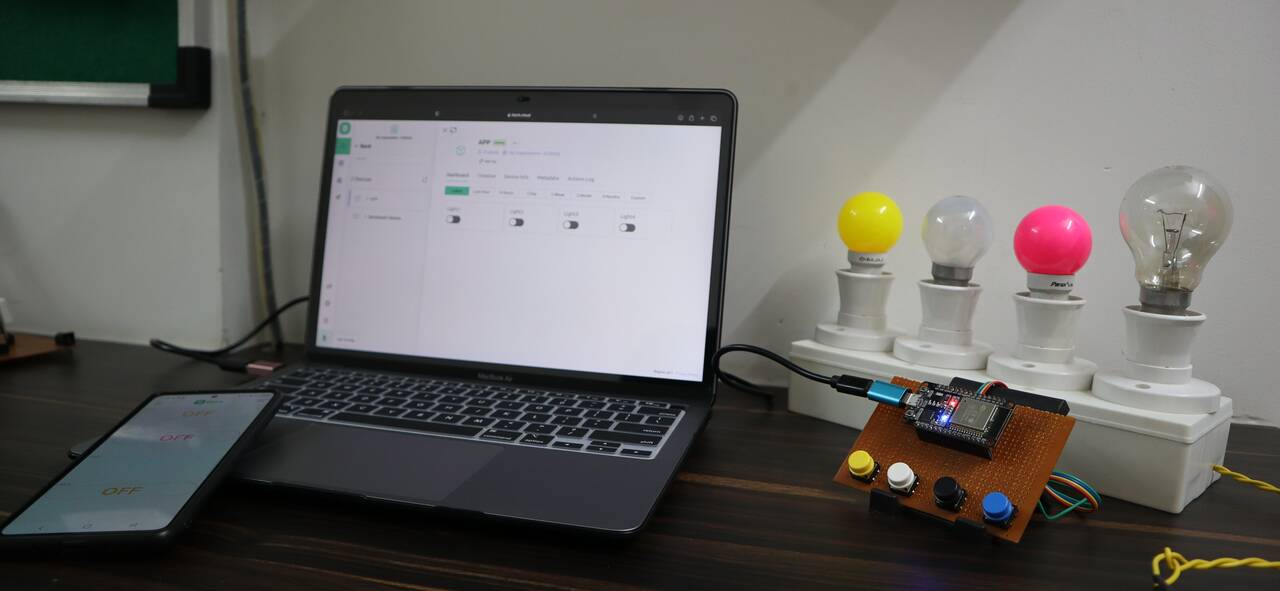
The ESP32 will connect to the WiFi Network and establishes the Connection with Blynk Web and Mobile Dashboard.
Now you can turn ON/OFF the relays from the Mobile and Web Dashboard. You just need to click the Dashboard button.
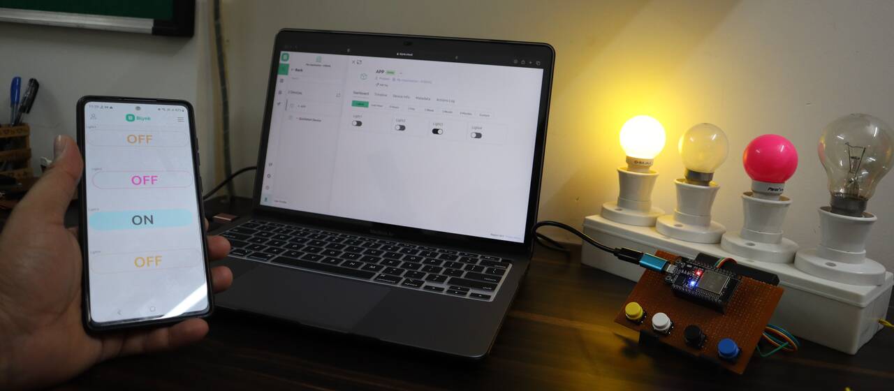
Apart from the Dashboard part, you can also press the Push Buttons manually to turn ON/OFF the Relay. The manual pressing will also be reflected on the Mobile/Web Dashboard.
This is how you can implement the Internet & Manual Control Home Automation System Project with Real-Time Feedback using ESP32 & New Blynk 2.0 IoT App.
Video Tutorial & Guide

 & Live Dashboard")


1 Comment
Hi, may I know. What board do I need to choose when I use arduino ide software for my esp32 wroom with external antenna ?