

Overview
In today’s fast-paced world of robotics, the MyArm 300 PI 2023 really shines as something special. Created by Elephant Robotics, this compact, desktop-sized robotic arm with seven axes is a clear sign of how far robotic technology has come and how it’s becoming more available to everyone.


In this article we will take a closer look at what makes the MyArm 300 PI 2023 so interesting, exploring its design, features, what it can do, the software it uses, the tools it comes with, and all the different ways it can be used.
Unboxing the MyArm 300 Pi from Elephant Robotics
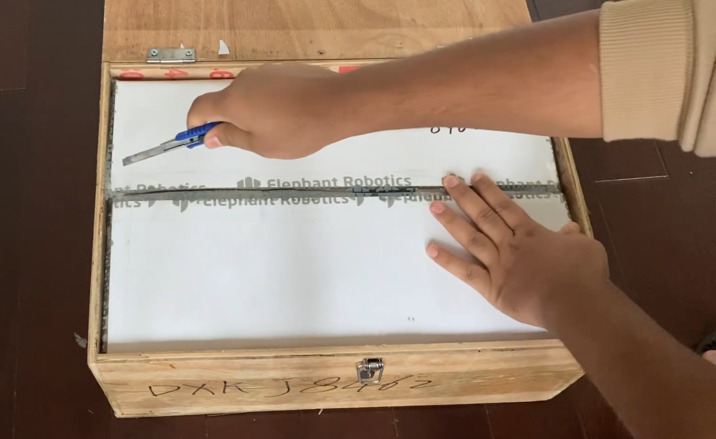
The Elephant Robotics sent the MyArm 300 Pi Robot to us just 1 week ago and we got the unit to review. It was sent in a protective wooden box.
As shown in the image, the product package includes the following items:
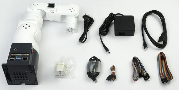
- myArm Robot
- Power Adapter
- Adapter Cable
- Adapter Cable Converter
- Dupont Wires
- Hex Wrench and M4 Screws
- HDMI Cable
- USB-C Cable
- LEGO Connectors
In addition to the above items, the package also contains a product certificate, product brochure, and desiccant.
MyArm 300 PI 2023 -7-Axis Robotic Arm Design
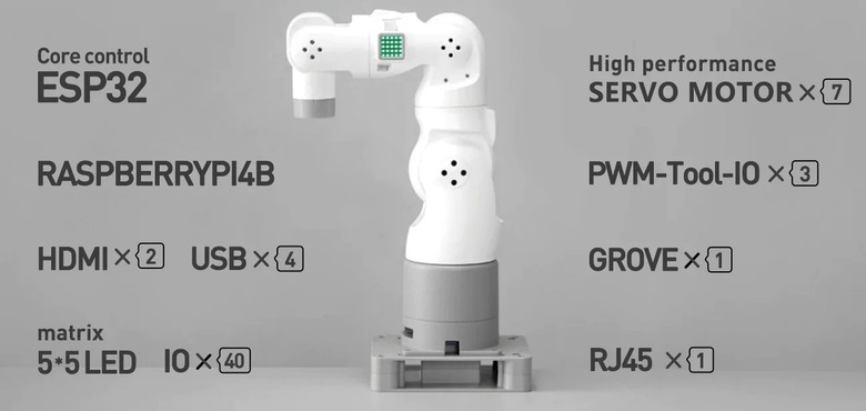
At the heart of the MyArm 300 PI 2023 is the Raspberry Pi 4B, paired with Elephant Robotics’ customized Ubuntu Mate 20.04 OS. This combination offers a PC-like experience, eliminating the need for external PC control.
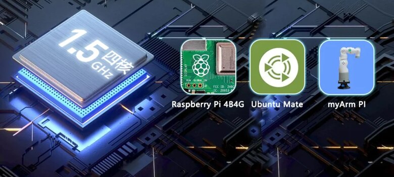
Users can simply connect a monitor, keyboard, and mouse for straightforward operation. The design is ideal for robotics education, control logic teaching, robot applications, and ROS simulation classes.
The MyArm boasts 7 degrees of freedom, surpassing traditional 6-DOF robots. This feature allows for movements as flexible and intricate as a human arm, making it an excellent tool for practical teaching in various complex areas such as robot posture research, motion path planning, redundancy management, kinematics, ROS development, and more.
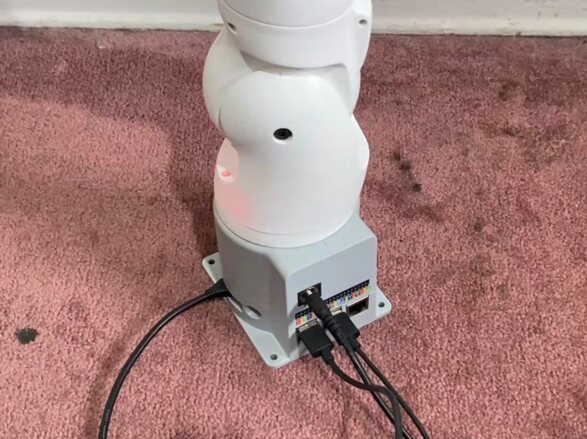
Base Electrical Interface Details
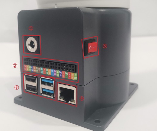
The front interface and switch of the base looks like this.
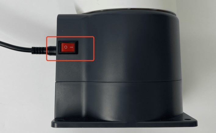
The side interface and switch of the base looks like this.
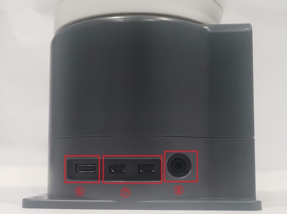
- Robotic Arm Charging Port: Uses a DC power socket with an outer diameter of 6.5mm and an inner diameter of 2.0mm. An 12V 5A DC power adapter provided by the manufacturer can be used to power the robotic arm.
- Bottom Pin Port
- USB2.0 and USB3.0 Interface: Uses serial bus standard 2.0 and 3.0 for data connection. Users can use the USB port to transfer program files or connect peripherals like mouse and keyboard.
- Ethernet Port: Data connection port for networking. Users can use the Ethernet interface for communication between the PC and the robot system or for Ethernet communication with other devices.
- Switch Button: Red represents the power switch, with “I” indicating “ON” and “O” indicating “OFF.”
- Raspberry Pi 4B built-in USB ports
- Display Port: HDMI port. This is an HDMI Type-D port. When connecting to a monitor, HDMI Interface 2 has a priority, so it is recommended to use HDMI Interface 1.
- Speaker and Headphone Jack
- HDMI Interface: This HDMI Type-D port is used for connecting to a monitor. HDMI Interface 2 is prioritized, so HDMI Interface 1 is recommended for use.
- SD Card Slot (H): A removable slot for an SD card, which stores the system internally.
Each of these components plays a crucial role in the functionality and versatility of the MyArm 300 PI 2023, enhancing its connectivity and user-friendliness.
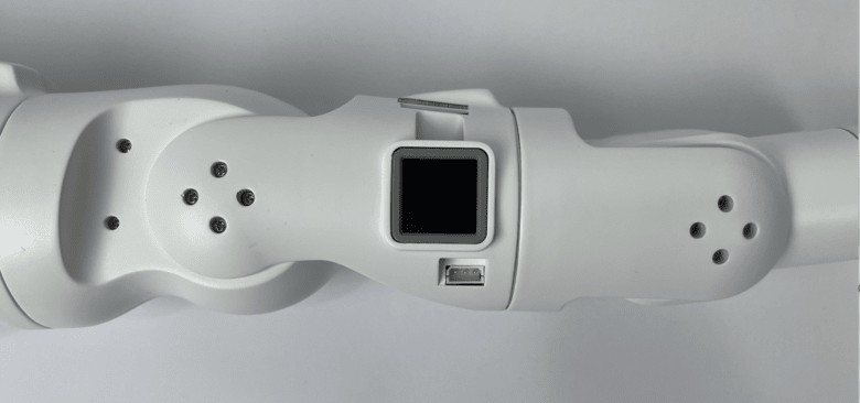
Robotic Arm End Electrical Interface
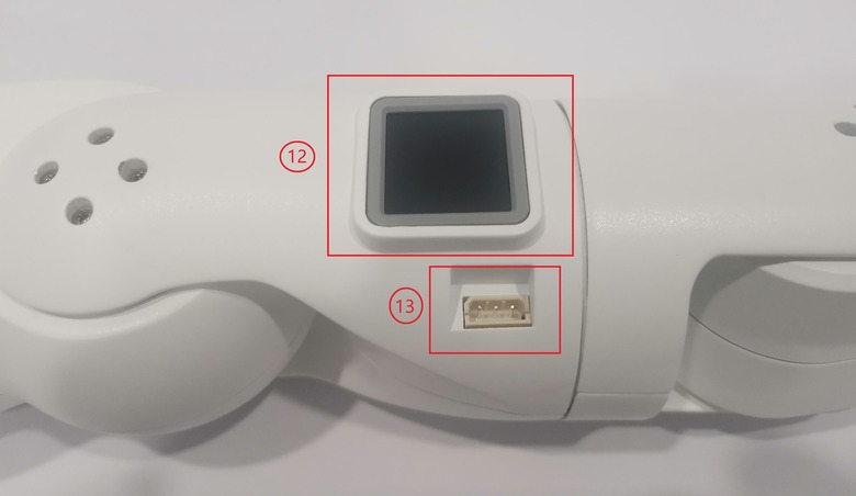
The side interface of the robotic arm end is shown in following figure.
⑨ End IO Interface
⑩ End Grove Interface
⑾ Type C Interface
⑿ End Atom
⒀ Servo Interface
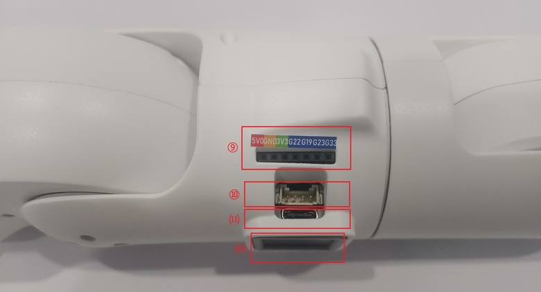
The arm has End Grove Interface, which includes a Type C Interface for PC communication and firmware updates, an Atom section for the 5X5 RGB LED display and key functions, and a Servo Interface designed for expanding the terminal gripper, currently compatible with the matching adaptive gripper.
Getting Started with MyArm 300 Pi 7-Axis Robotic Arm
Before starting this process, ensure your device is in proper condition. Read and adhere to the Safety Instructions. Make sure your working environment is safe. After securing the robotic arm base, connect the external devices and prepare for startup.
The first step that we need is to connect the Desktop Monitor. In my case I am using “7-inch HDMI Screen” from SunFounder.
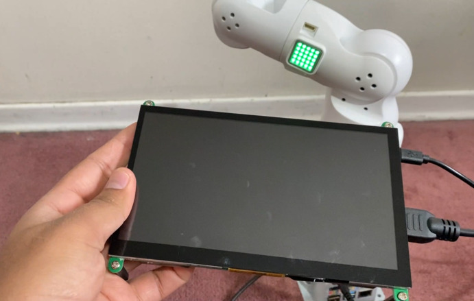
First, plug the HDMI cable into the monitor’s HDMI port. Next, insert the other end into the Expansion Panel’s lower left side HDMI port of the robotic arm. Ensure you check the orientation before inserting to prevent damaging the port.
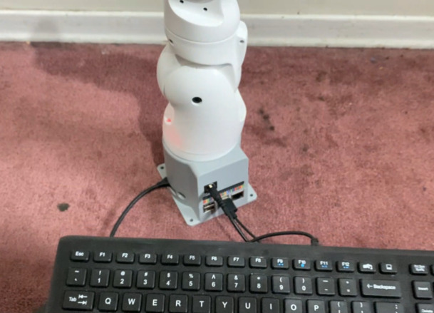
The next step is to connect Mouse, Keyboard, and Other Peripherals.
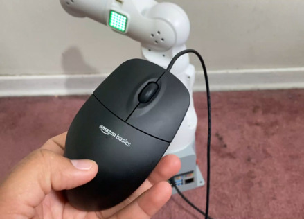
The USB port can be used to connect devices that communicate via USB, including keyboards and mice.
The robot requires an external power source. Its rated voltage as 8.4V 5A DC. Plug in the DC Power Adapter.
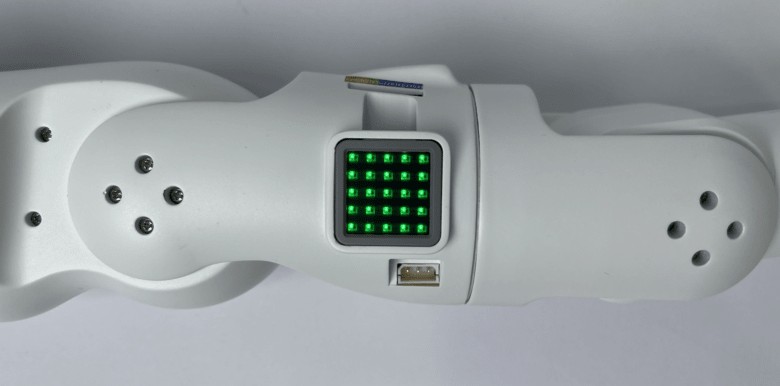
After connecting the necessary external devices and the robot’s power source, press the red power button to turn on the robot. Once pressed, the ATOM LED on the robot’s arm will light up in green. Here’s what you can expect:
- When the robot is off, the AtomLED is off, and the robot joints don’t exert torque. You can manually position the joints.

- Gently press the power button to turn it on.

- When the robot is on, the AtomLED is brightly lit, and the robot joints exert torque. You cannot manually position the joints.

After powering on, the robot will perform a system self-check. If there are no malfunctions, it will boot to the system desktop, as shown below:
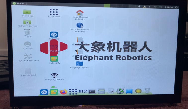
If your robot starts up successfully, congratulations! You have completed the robot’s startup process. Continue by reading the robot’s basic functionality and extended development application chapters to learn how to use the robot.
Ubuntu Mate 20.04 System
The Ubuntu Mate 20.04 System stands out as a popular choice in the Linux operating system landscape, particularly for personal desktop use. Its user-friendly nature makes it an ideal platform for those new to Linux or working with embedded hardware operating systems. Significantly, Ubuntu offers a version specifically optimized for the Raspberry Pi, enhancing its versatility and accessibility.
In terms of enhancements, our system diverges from the official release in several key aspects. It seamlessly integrates Python, Ros1, and Ros2 environments, enabling users to engage with built-in software immediately, without the hassle of additional setups. Furthermore, essential operating software such as myStudio and myBlockly come pre-installed, simplifying the user experience by removing the need for manual installation. Additionally, the system is equipped with VNC screen-sharing capabilities. Upon booting, it automatically creates its own hotspot, facilitating remote access to the screen via VNC, thus eliminating the necessity for a connected physical display.
The Raspberry Pi version of the system is particularly noteworthy for its comprehensive pre-built development environment. This environment grants users immediate access to a range of software tools, designed to enhance both the efficiency and ease of their programming and development tasks.
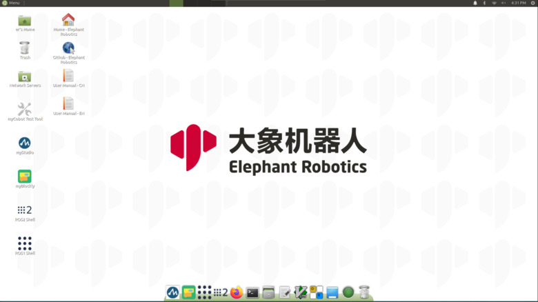
1. Desktop Screen
The desktop screen has the following files, folders, and shortcuts.
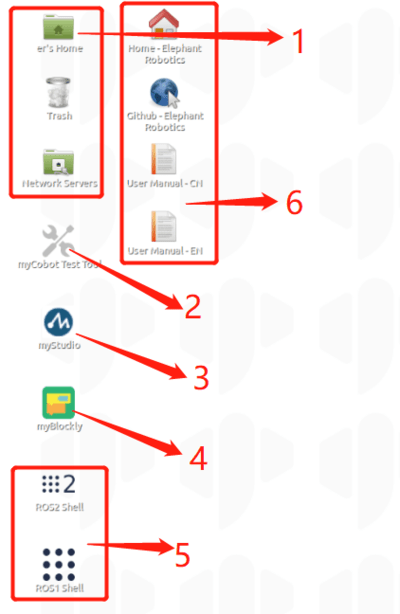
- System Folders and Recycle bin
- A test tool to test whether myCobot is functioning normally
- myStudio: It can burn firmware to the robot arm
- myBlockly: Visual modular programming software
- Ros1/Ros2:It is a highly flexible software architecture for writing robot software programs.
- Browser and link: Can jump to our official website and Gitbook (need to be connected to the Internet)
2. Toolbars
Similarly, the Toolbars have the following software.
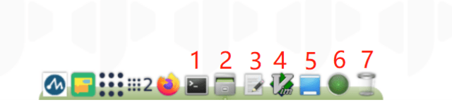
- Terminal for command line interface
- File manager for accessing system resources
- Notepad and Vim for script and text editing
- Direct desktop display option
- CPU and memory usage monitor
- Recycle Bin for temporary file storage and recovery
3. Built-in Software:
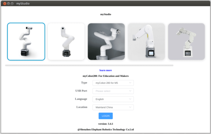
- myStudio: Offers firmware burning and updating, tutorial data (including user manuals and videos), and maintenance information.
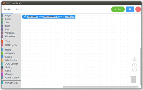
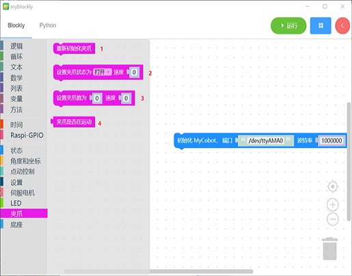
- myBlockly: A puzzle programming software based on Python and pymycobot libraries. It’s ideal for programming learners, enhancing their logic skills. myBlockly also features a Python display interface, converting block-built programs into Python code, aiding in learning Python syntax.
For detailed introductions and usage instructions for these software tools, users can access specific guides and case studies through the download links.
WiFi Connection & Accessing via VNC Viewer
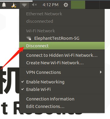
There are two wireless connection modes. The first mode requires an external monitor to do some operations on the system. The specific steps are as follows:
Click “Disconnect”, and disconnect the default hotspot connection.
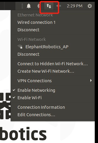
Click “Enable Wi-Fi”, and the currently available WiFi will appear.
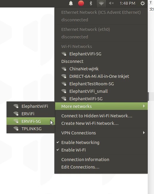
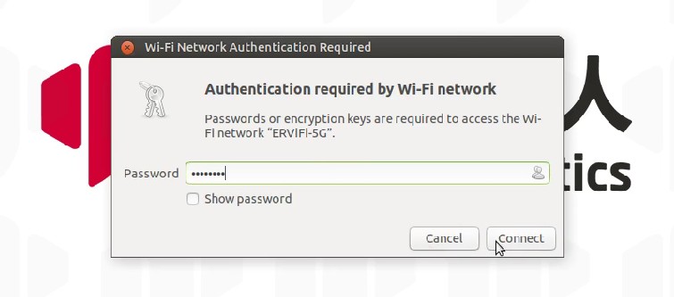
Click on the WiFi you need to connect to and enter the password.
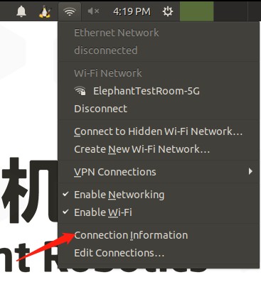
After connecting successfully, click “Connection Information” to check the IP address of the robot.
As shown in the example, “192.168.10.64” is the current IP address of the robot.
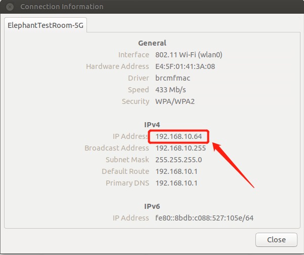
Connect your PC and the robot to the same WiFi, open the VNC viewer, enter the IP address(examples: input 192.168.10.64), and enter the password Elephant, The user name is not specified by default. The following is an example of a successful connection.
Development environment included in the system
1. Development based on ROS (Ros1/Ros2)
ROS is open-source and is a post-operating system, or secondary operating system, used for robot control. With the use of ROS, the simulation control of the manipulator can be realized in the virtual environment. The robotic arm can be visualized through the rviz platform, and operate the robotic arm in a variety of ways.
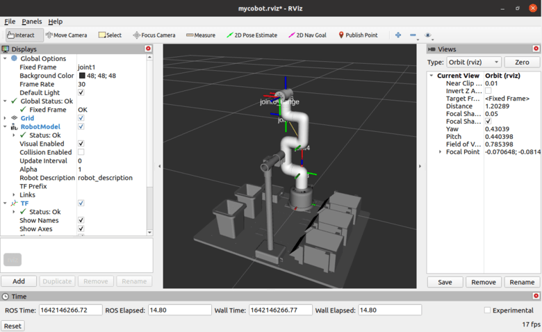
It can also be used to plan and execute the robotic arm’s action path to freely control the robotic arm. After installing the ROS development environment, refer to use cases and use of moveit for more information.
2. Development based on Python
The robots support Python and the development of the Python API library has become increasingly complete.
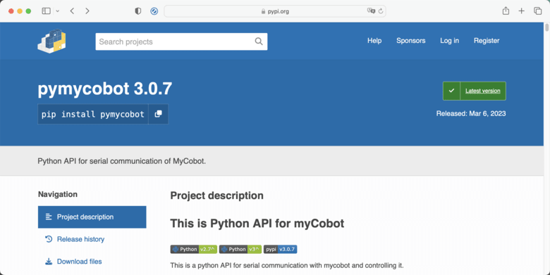
The joint angle, coordinates, gripper, and other aspects of the robot can be controlled via Python. Refer to installing the python environment, for more information.
3. Development based on myBlockly
myBlockly is a fully visual modular programming software that belongs to the graphical programming language.
Video Tutorial & Guide

Purchase Links
Discover unbeatable Black Friday and Cyber Monday deals on Elephant Robotics’ innovative products!

Visit the special event page at Black Friday Offer to access exclusive discounts and offers, ensuring you get the best value on cutting-edge robotics technology. Don’t miss out on these huge savings!
Conclusion: A Step into the Future of Robotics
The MyArm 300 PI 2023 is more than just a robotic arm; it’s a symbol of the future of robotics. Its combination of advanced features, ease of use, and wide range of applications make it an invaluable tool for educators, researchers, hobbyists, and industry professionals. As we continue to explore the potential of robotics, the MyArm 300 PI 2023 stands as a testament to the innovation and accessibility that is driving this field forward.
In conclusion, the MyArm 300 PI 2023 by Elephant Robotics is not just a product; it’s a revolution in the world of robotics. Its impact extends beyond its immediate functionality, inspiring a new generation of roboticists and technologists to push the boundaries of what’s possible.


