

Overview
In this project, we interfaced LM35 Temperature Sensor with Arduino to design a digital thermometer. The measured temperature will be directly displayed on a 16*2 LCD. Earlier we learned about DS18B20, MAX6675 & MLX90614 digital temperature Sensors. But LM35 is an analog temperature sensor.
LM35DZ is capable of reading the temperature in Centigrade scale. The output voltage of the sensor is directly proportional to the temperature in centigrade. LM35 can be used in the range of -55°C to +150°C with +/- 0.75°C accuracy. So let’s learn how to design a Digital Thermometer Using Arduino & LM35 Temperature Sensor.
Bill of Materials
We need the following components for designing a digital thermometer.
| S.N. | Components Name | Quantity | Purchase Links |
|---|---|---|---|
| 1 | Arduino UNO Board | 1 | Amazon | AliExpress |
| 2 | LM35 Temperature Sensor | 1 | Amazon | AliExpress |
| 3 | 16x2 LCD Display | 1 | Amazon | AliExpress |
| 4 | Potentiometer 10K | 1 | Amazon | AliExpress |
| 5 | Connecting Wires | 20 | Amazon | AliExpress |
| 6 | Breadboard | 1 | Amazon | AliExpress |
LM35 Temperature Sensor:
The LM35 series are precision integrated-circuit temperature devices with an output voltage linearly-proportional to the Centigrade temperature. The LM35 device has an advantage over linear temperature sensors calibrated in Kelvin, as the user is not required to subtract a large constant voltage from the output to obtain convenient Centigrade scaling. The LM35 device does not require any external calibration or trimming to provide typical accuracies of ±¼°C at room temperature and ±¾°C over a full −55°C to 150°C temperature range.

Lower cost is assured by trimming and calibration at the wafer level. The low-output impedance, linear output, and precise inherent calibration of the LM35 device make interfacing to readout or control circuitry especially easy. The device is used with single power supplies, or with plus and minus supplies. As the LM35 device draws only 60 µA from the supply, it has a very low self-heating of less than 0.1°C in still air.
Features
- Calibrated directly in Degree Celsius (Centigrade)
- Linear at 10.0 mV/°C scale factor
- 0.5°C accuracy guarantee-able (at a25°C)
- Rated for full -55°C to a 150°C range
- Suitable for remote applications
- Low cost due to wafer-level trimming
- Operates from 4 to 30 volts
- Less than 60 mA current drain
- Low self-heating, 0.08°C instill an air
- Non-linearity only 0.25°C typical
- Low impedance output, 0.1Ωfor 1 mA load
Working
In order to understand the working principle of the lm35 temperature sensor, we have to understand the linear scale factor. In the features of lm35, it is given to be +10 mills volt per degree centigrade. It means that with an increase in output of 10 mills volt by the sensor out pin the temperature value increases by one. For example, if the sensor is outputting 100 mills volt at vout pin the temperature in centigrade will be 10-degree centigrade. The same goes for the negative temperature reading. If the sensor is outputting -100 mills volt the temperature will be -10 degrees Celsius.

The circuit diagram is shown above. Briefly, there are two transistors in the center of the drawing. One has ten times the emitter area of the other. This means it has one-tenth of the current density since the same current is going through both transistors. This causes a voltage across the resistor R1 that is proportional to the absolute temperature and is almost linear across the range we care about. The “almost” part is taken care of by a special circuit that straightens out the slightly curved graph of voltage versus temperature. The amplifier at the top ensures that the voltage at the base of the left transistor (Q1) is proportional to absolute temperature (PTAT) by comparing the output of the two transistors.
The amplifier at the right converts absolute temperature (measured in Kelvin) into either Fahrenheit or Celsius, depending on the part (LM34 or LM35). The little circle with the “i” in it is a constant current source circuit. The two resistors are calibrated in the factory to produce a highly accurate temperature sensor. The integrated circuit has many transistors in it — two in the middle, some in each amplifier, some in the constant current source, and some in the curvature compensation circuit. All of that is fit into the tiny package with three leads.
Interfacing LM35 Temperature Sensor with Arduino
Let us interface the LM35 Temperature Sensor with the Arduino UNO Board. The connection diagram is so simple.

- Connect the VCC of the LM35 to 5V on the Arduino.
- Connect the GND of the LM35 to GND on the Arduino.
- Finally, connect the Vout (output) of the LM35 to one of the Arduino’s analog input pins (e.g., A0).

You can use a breadboard for connection and connect using the jumper wires.
Source Code/Program for Reading Temperature Value
Let us take a look at the code for reading temperature reading from LM35 Temperature Sensor using Arduino Board.
The temperature in degrees Celsius is calculated by reading the analog voltage output from the LM35 sensor, converting that reading to a voltage value, and then converting this voltage into a temperature. The formula used is:
Temperature (°C) = (Sensor Value × 5.0⁄1024.0) × 100.0
This formula takes the analog sensor value (0-1023), scales it to a 0-5V range (because the Arduino analog inputs map 0-5V to 0-1023), and then multiplies by 100 because the LM35 increases 10mV (or 0.01V) per degree Celsius, effectively converting the voltage to temperature.
The following code reads temperature data from an LM35 sensor connected to an Arduino and calculates the temperature in both Celsius and Fahrenheit. It then prints these temperature readings to the Serial Monitor every second, allowing for real-time monitoring of the sensor’s output.
|
1 2 3 4 5 6 7 8 9 10 11 12 13 14 15 16 17 18 19 20 21 22 23 24 25 26 27 28 29 30 31 |
// Define the LM35 sensor input pin const int lm35Pin = A0; void setup() { // Begin Serial Communication at 9600 baud rate Serial.begin(9600); } void loop() { // Read the value from the sensor int sensorValue = analogRead(lm35Pin); // Convert the sensor reading to temperature in degree Celsius float temperatureC = sensorValue * (5.0 / 1024.0) * 100.0; // Convert Celsius to Fahrenheit float temperatureF = (temperatureC * 1.8) + 32; // Print the temperature in Celsius to the Serial Monitor Serial.print("Temperature: "); Serial.print(temperatureC); Serial.print("°C, "); // Print the temperature in Fahrenheit to the Serial Monitor Serial.print(temperatureF); Serial.println("°F"); // Wait 1 second before reading again delay(1000); } |
Upload the code to the Arduino UNO Board and open the Serial Monitor, once uploading is completed.
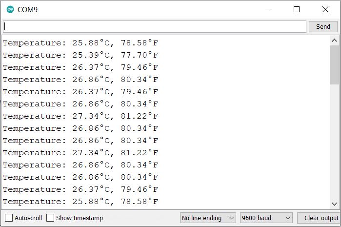
The Serial Monitor will show the value of temperature reading in both Celsius and Fahrenheit readings.
Interfacing LM35 Temperature Sensor with Arduino & LCD Display
Now let us add a 16×2 I2C LCD Display to the above circuit, so that we can display the LM35 Temperature readings on LCD Screen using the modified Arduino Code.

- Connect the VCC of the LCD to 5V on the Arduino.
- Also, connect the GND of the LCD to GND on the Arduino.
- Connect the SDA Pin of the LCD to A4 on the Arduino
- Finally, connect the SCL Pin of the LCD to A5 on the Arduino

Source Code/Program for Displaying LM35 Temperature Values on LCD
The following code interfaces an Arduino with a 16×2 LCD display using I2C communication to create a digital thermometer. It reads the temperature from an LM35 sensor, displays the temperature in both Celsius and Fahrenheit on the LCD, and updates the display every 2 seconds. A custom character is used to display the degree symbol next to the temperature values.
Before compiling the code, add I2C LCD Library to the Arduino library folder.
|
1 2 3 4 5 6 7 8 9 10 11 12 13 14 15 16 17 18 19 20 21 22 23 24 25 26 27 28 29 30 31 32 33 34 35 36 37 38 39 40 41 42 43 44 45 46 47 48 49 50 51 52 53 54 55 56 |
#include <Wire.h> #include <LiquidCrystal_I2C.h> // Initialize the library with the I2C address of the display (usually 0x27 or 0x3F) LiquidCrystal_I2C lcd(0x27, 16, 2); #define sensor A0 byte degree[8] = { 0b00110, 0b00110, 0b00000, 0b00000, 0b00000, 0b00000, 0b00000, 0b00000 }; void setup() { lcd.init(); // initialize the lcd lcd.backlight(); lcd.createChar(1, degree); lcd.setCursor(0, 0); lcd.print("Digital Thermometer"); delay(2000); lcd.clear(); } void loop() { /*---------Temperature-------*/ float reading = analogRead(sensor); float temperatureC = reading * (5.0 / 1023.0) * 100; // Convert Celsius to Fahrenheit float temperatureF = (temperatureC * 1.8) + 32; /*------Display Result in Celsius------*/ lcd.clear(); lcd.setCursor(0, 0); lcd.print("Temp: "); lcd.print(temperatureC); lcd.write(1); // Degree symbol lcd.print("C"); /*------Display Result in Fahrenheit------*/ lcd.setCursor(0, 1); lcd.print("Temp: "); lcd.print(temperatureF); lcd.write(1); // Degree symbol lcd.print("F"); delay(2000); // Update every 2 seconds } |
Upload the above code to the Arduino Board. The LCD will start displaying the temperature reading both in degree Celsius & Fahrenheit Scale.

Video Demonstration & Explanation:
Watch this video tutorial that explains all about Digital Thermometer Using Arduino & LM35 Temperature Sensor.

The LM35 Temperature Sensor can be interfaced with ESP32 Web Server to display the temperature readings on a web page.

")


8 Comments
why this byte degree(8) function is used in this program.please explain me
It is used for displaying degree sign.
okay. thank you.
Do I need to first test my lcd working with arduino? or can i just directly connect like the above circuit and tset the circuit directly?
I have few doubts plz contact me. It’s very important
Plz contact me. I have few doubts.
why does it say exit status 1
‘LiquidCrystal’ does not name a type
when u upload it ?
Sir We uploaded the laptop there but the lcd display does not make sense at all temperature