

Overview
In this project, you will learn how to make your own Infrared Thermometer using MLX90614 Infrared Temperature Sensor & Arduino Board. You can display the temperature reading on SSD1306 0.96″ OLED Display. Earlier we used temperature Sensors like DS18B20, LM35 & MAX6675. However, these temperature sensors only sense the temperature when the heat is applied to them directly on their surface. But if you wish to measure the temperature of a very hot body like a flame or hot iron, you can’t rely on these sensors.
We need some sensors that can measure the temperature without any contact & sensing the temperature through IR is the best method. For this, you can use the MLX90614 infrared thermometer from Melexis for this project. The MLX90614 sensor uses contactless temperature sensing to measure the temperature data without any physical contact to particular surface.

In this project we will interface MLX90614 with Arduino Board and use the laser diode to point the sensor to a particular object. The refresh rate and sensitivity of MLX90614 are very high that it can give the reading within a fraction of a second. You can use MLX90614 to measure the temperature of a hot object like machines, flames, hot iron, device CPU. You can even use this sensor for laboratory purposes, i.e. MLX90614 can also be used as an infrared thermometer for measuring the body temperature. Due to COVID-19, the demand for this sensor has increased within the last few months. The MLX90614 Sensor requires some calibration in Arduino Code which we will learn in this post.
Bill of Materials
All the components that you need for this project can be ordered online from the Amazon. The components purchase link is given as well.

| S.N. | Components Name | Quantity | Purchase Links |
|---|---|---|---|
| 1 | Arduino Pro Mini | 1 | Amazon | AliExpress |
| 2 | MLX90614 IR Temperature Sensor | 1 | Amazon | AliExpress |
| 3 | 0.96" I2C OLED Display | 1 | Amazon | AliExpress |
| 4 | Laser Diode Module | 1 | Amazon | AliExpress |
| 5 | 3.7V, 1000 mAh Lithium Ion Battery | 1 | Amazon | AliExpress |
| 6 | Connecting Jumper Wires | 20 | Amazon | AliExpress |
| 7 | Momentary Push Switch | 1 | Amazon | AliExpress |
MLX90614 Contactless Infrared Temperature Sensor

The MLX90614 is an infrared thermometer for non-contact temperature measurements capable of measuring temperature between -70 to 380°C. The sensor uses IR sensitive thermopile detector chip and the signal conditioning ASIC integrated into a single chip. The thermometer comes factory calibrated with a digital SMBus output giving full access to the measured temperature in the complete temperature range(s) with a resolution of 0.02°C. Even though it works on SMBus protocol, but can be used with I2C pins.
MLX90614 Pinout Configuration

The MLX90614 sensor has 4 pins. The working voltage of the sensor is 3.6V to 5V but the 3.3V version is also available. It has I2C Pins as SDA & SCL. The SDA is the Serial data pin & SCL is the Serial Clock pin used for I2C Communication.
Specifications
1. Operating Voltage: 3.6V to 5V
2. Supply Current: 1.5mA
3. Object Temperature Range: -70°C to 382°C
4. Ambient Temperature Range: -40°C to 125°C
5. Accuracy: 0.02°C
6. Field of View: 80°
7. Distance between object and sensor: approx. 2cm-5cm

Working Principle of MLX90614
As mentioned earlier, the MLX90614 sensor can measure the temperature of an object with any physical contact. This is often made possible with a law called Stefan-Boltzmann Law, which states that each one objects and living beings emit IR Energy and therefore the intensity of this emitted IR energy is going to be directly proportional to the temperature of that object or living being. Therefore the MLX90614 sensor calculates the temperature of an object by measuring the quantity of IR energy emitted from it.
Applications of MLX90614
1. High precision non-contact temperature measurements
2. Thermal Comfort sensor for Mobile Air Conditioning control system
3. Temperature sensing element for residential, commercial & industrial building air
4. Automotive blind angle detection
5. Industrial temperature control of moving parts
6. Healthcare
7. Livestock monitoring
8. Movement detection
9. Thermal relay/alert
10. Body temperature measurement
Circuit Diagram: Infrared Thermometer using MLX90614 Arduino & OLED
The Circuit diagram for making an Infrared Thermometr using MLX90614, Arduino, OLED Display & Battery is given below.

The circuit has Arduino Pro Mini Board which is used because of the small and compact size. The Arduino Pro Mini Board has 2 versions, one of them works at 5V, 16MHz, and the other at 3.3V, 8 MHz. You can select 3.3V, 8MHz Arduino Pro Mini as you are powering the device using 3.7V Lithium-Ion Battery. The RAW pin of Arduino pro-Mini is directly connected to the battery VCC Pin via a push switch.
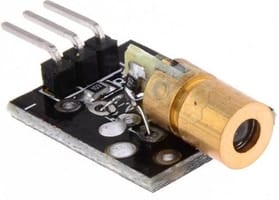
To point the object, you can use Laser Diode Breakout Board. Laser Diode Module is a low-cost module with having a wavelength of 650nm and an operating voltage of 3V-5V. The laser head is composed of a light-emitting tube, condenser lens, and adjustable copper sleeve. It can work directly after connecting to a dc power supply. In our circuit, we connect the Laser Diode output pin to D12 of Arduino Pro Mini. To learn more about the Laser Diode Module, you can check one of the Laser Diode Arduino projects.
The MLX90614 contactless infrared temperature sensor & 0.96″ I2C OLED Display is connected to I2C Pin of Pro Mini Board. The SDA and SCL pin is connected to A4 & A5 of Pro Mini respectively. The OLED Display and MLX90614 both works at 3.3V, hence their VCC can be connected to 3.3V of Pro Mini.

3D Casing Design for Temperature/Thermal Gun
To make the thermal GUN, we used a 3D Casing designed using a 3D Modelling Software. The outer casing involves the two-part. The top part consists of a cuboid where the entire component including Arduino Pro Mini, OLED Display, Lithium-Ion Battery, Laser Diode & MLX90614 Sensor can be placed. There are two holes on the outer point part of the Thermal Gun. One hole is for the MLX90614 Infrared Thermometer & other for the Laser Diode.

The base of the Temperature Gun can be attached via glue to the top part. You can place the small battery in the base in case if you don’t want a Lithium-Ion Battery. The switch is also added to the base which is used to turn ON or OFF the entire circuit.

Download the Casing STL Files from this link: Thermal Gun
First connect all the components to the Arduino Pro Mini Board and then place the entire components inside the 3D casing unit as shown in the image below.

On the base part of the 3D model, connect and tighten the ON/OFF Switch. This part can behold on the hand and you can press the ON/OFF button by simply holding the Thermal Gun on your hand.

MLX90614 Arduino Library
The Arduino IDE requires MLX90614 Library to interface the MLX90614 with Arduino Board. The library is built by Sparkfun & Adafruit both. The Adafruit & Sparkfun MLX90614 is the library that interfaces with the MLX90614 non-contact infrared thermometer over a 2-wire, I2C-like interface (SMBus).
You can use any of the libraries for Interfacing applications. The library has an example code for Interfacing the MLX90614 Sensor with Arduino. The sensor is factory calibrated and hence it acts like a plug and plays sensor module for speeding up development processes.
1. Download Adafruit MLX90614 Library
2. Download Sparkfun MLX90614 Library
In my case I am using Adafruit MLX90614 Library.
Source Code/program
The Source Code or program for MLX90614 with Arduino is given below. To upload the code to the Arduino Pro Mini Board, you need USB-TTL Converter Module (FTDI Module).
Apart from MLX90614 Library, you also need Library for OLED Display. The SSD1306 OLED Display requires two libraries. You can download the libraries from the link below.
1. Adafruit SSD1306 Library: Download
2. Adafruit GFX Library: Download
|
1 2 3 4 5 6 7 8 9 10 11 12 13 14 15 16 17 18 19 20 21 22 23 24 25 26 27 28 29 30 31 32 33 34 35 36 37 38 39 40 41 42 43 44 45 46 47 48 49 50 51 52 53 54 55 56 57 58 59 60 61 62 63 64 65 66 67 68 69 70 |
#include <Wire.h> #include <Adafruit_MLX90614.h> #include <Adafruit_GFX.h> #include <Adafruit_SSD1306.h> #define SCREEN_WIDTH 128 // OLED display width, in pixels #define SCREEN_HEIGHT 64 // OLED display height, in pixels #define OLED_RESET -1 // Reset pin # (or -1 if sharing Arduino reset pin) Adafruit_SSD1306 display(SCREEN_WIDTH, SCREEN_HEIGHT, &Wire, OLED_RESET); #define laser 12 Adafruit_MLX90614 mlx = Adafruit_MLX90614(); double temp_amb; double temp_obj; void setup() { Serial.begin(9600); mlx.begin(); //Initialize MLX90614 display.begin(SSD1306_SWITCHCAPVCC, 0x3C); //initialize with the I2C addr 0x3C (128x64) Serial.println("Temperature Sensor MLX90614"); pinMode(laser, OUTPUT); // Connect LASER digitalWrite(laser, LOW); display.clearDisplay(); display.setCursor(25,15); display.setTextSize(1); display.setTextColor(WHITE); display.println(" Thermometer"); display.setCursor(25,35); display.setTextSize(1); display.print("Initializing"); display.display(); delay(5000); } void loop() { //Reading room temperature and object temp //for reading Fahrenheit values, use //mlx.readAmbientTempF() , mlx.readObjectTempF() ) temp_amb = mlx.readAmbientTempC(); temp_obj = mlx.readObjectTempC(); digitalWrite(laser, HIGH); //Serial Monitor Serial.print("Room Temp = "); Serial.println(temp_amb); Serial.print("Object temp = "); Serial.println(temp_obj); display.clearDisplay(); display.setCursor(25,10); display.setTextSize(1); display.setTextColor(WHITE); display.println(" Temperature"); display.setCursor(25,30); display.setTextSize(2); display.print(temp_obj); display.print((char)247); display.print("C"); display.display(); delay(1000); } |
Testing Arduino Thermal/temperature Gun
After uploading the code to the Arduino Pro-Mini Board using FTDI Module, the device is ready for testing. Now, you can Power ON the circuit by pressing the Push Button Switch. Once powered on, the device will take 5 seconds to get initialized which will be displayed on OLED Display. Once initializing is done, the Laser will get turn ON and OLED will start displaying the Temperature.
Now you can point the Laser from Thermal Gun to Human Forehead and also to any hot body, the OLED Display will display the temperature quickly as it has fast response output.

The entire working process of the device is explained in the video below. You can follow the video guide if you have any doubt or queries.
Video Tutorial & Guide

You can also make a better version of this project by sending the MLX90614 Sensor Data to Cloud. One of the best example post to do that is given here: IoT Based IR Thermometer. The Ambient Temperature & Object Temperature Data is being sent to Blynk Application over cloud.
In conclusion, the MLX90614 Infrared Temperature Sensor is a highly efficient and precise tool for measuring temperature without any physical contact. The combination of this sensor with the Arduino Board and OLED Display makes it easy to use and accessible for various applications such as measuring the temperature of hot objects, device CPU, body temperature, and more. This project provides an opportunity for individuals to learn about infrared temperature sensing and the use of MLX90614 in real-world applications. With its high refresh rate and sensitivity, MLX90614 is a must-have tool for anyone looking to measure temperature accurately and efficiently.
A Thermal Camera can be made using a similar sensor Thermal Sensor called AMG8833 Thermal Image Sensor & Raspberry Pi 4.
You can also build a High Resolution Thermal Camera using the MLX90640 Thermal image array temperature sensor.

")


16 Comments
I assembled all everthing same with even your code. once l executed it, it gives that error:
Any idea please?
Blink:2:10: fatal error: Adafruit_MLX90614.h: No such file or directory
#include <Adafruit_MLX90614.h>
^~~~~~~~~~~~~~~~~~~~~
compilation terminated.
exit status 1
Adafruit_MLX90614.h: No such file or directory
Please add MLX90614 library to arduino ide
Greatly appreciated for your help. I am new working with multiple file structures in this language. If it is possible to take your time like 5 minutes via zoom please. Thanks again.
here is email: [email protected]
Facebook : https://www.facebook.com/adem.gokce.3979
Kik. : adem122333
Best Regards,
where is the calibrate here sir?
Add a few numbers, i.e Calibration factor to these lines like temp_obj + x.
Serial.println(temp_obj);
display.print(temp_obj);
Thanks for sharing this great project!
I built and uploaded the code – all works perfectly EXCEPT the display freezes at 292 C and will not go higher. What would cause this? I am at a loss. I’ve tried tweaking almost everything.
can you tell us which pins we connect the laser diode to
Check the code to find which pin is defined for Laser.
Nice project. I developed similar project with another version of IR sensor that integrates mlx90614 and a serial output signal. This module is coded as mcu90614.
if we want to add the buzzer in it, then whats the code for it?
does the code works at arduino UNO or i should buy nano?
The code will work for arduino uno, nano, pro mini etc.
Sir Can you provide the library of MLX90614 for Proteus… I want to simulate it with arduino nano. Hoping for a quick reply 😀
which jumper wires have you used?
In file included from C:\Users\hp\Documents\Arduino\gj1\42\42.ino:2:0:
C:\Users\hp\Documents\Arduino\libraries\Adafruit_MLX90614_Library/Adafruit_MLX90614.h:18:10: fatal error: Adafruit_I2CDevice.h: No such file or directory
#include <Adafruit_I2CDevice.h>
^~~~~~~~~~~~~~~~~~~~~~
I`M Getting error any idea why?
In section “MLX90614 Pinout Configuration”, the image on the right, the pinouts are incorrect.
Viewed from the sensor bottom (as shown), beginning at the index tab and moving CCW:
VSS (Ground)
VDD (Power +)
SCA (Data)
SCL (Clock)
See MLX90614 datasheet, page 8, chapter 6.