

Overview
In this project, we will build our own IoT Based IR Thermometer using MLX90614 & ESP8266 & monitor the temperature on the Blynk Application. This DIY Infrared Thermometer is the low-cost contactless Thermometer for measuring body temperature or the temperature of very hot bodies. An infrared thermometer is a device that measures the infrared radiation emitted by an object. Infrared radiation means a type of electromagnetic radiation below the visible spectrum of light.
The IR Temperature Sensor MLX90614 from Melexis can be easily connected to any microcontroller using the SMBus Protocol, which is similar to I2C Protocol. Here, we will interface MLX90614 Sensor with NodeMCU ESP8266 & 0.96″ OLED Display.

We will connect the ESP8266 to the WiFi Network & send the temperature data, i.e Ambient Temperature & Object Temperature to the Blynk Application Dashboard. Blynk is an IoT platform that allows you to quickly build interfaces for controlling and monitoring your hardware sensors from your Smartphone.
Bill of Materials
The IoT Based IR Thermometer requires following components. All the components can be easily purchased from Amazon. The component purchase link is given below.
| S.N. | Components Name | Quantity | Purchase Links |
|---|---|---|---|
| 1 | NodeMCU ESP8266 Board | 1 | Amazon | AliExpress |
| 2 | MLX90614 IR Temperature Sensor | 1 | Amazon | AliExpress |
| 3 | 0.96" I2C OLED Display | 1 | Amazon | AliExpress |
| 4 | Connecting Wires | 10 | Amazon | AliExpress |
| 5 | Breadboard | 1 | Amazon | AliExpress |
MLX90614 Contactless IR Temperature Sensor
The MLX90614 is a Contactless Infrared (IR) Digital Temperature Sensor from Melexis. The sensor can be used to measure the temperature of a particular object between -70°C to 382.2°C. The sensor uses IR rays to measure the temperature of the object without any physical contact. You can check the working principle of the IR Thermometer here: IR Thermometer Working.

The MLX90614 sensor communicates to the microcontroller using the SMBus Protocol which is similar to the I2C protocol. Thus the sensor has 4 pins: VCC, GND, SDA & SCL. The sensor operates between 3.3V to 5V with a current requirement of 1.5mA. The accuracy of the sensor is 0.02°C. The sensor has a 17-bit ADC which allows reading the temperature with a smaller resolution of 0.0007. The best way to read the accurate sensor data is by placing the sensor at a distance of 2cm-5cm with a field of view at 80° angle.
You can learn in detail about the MLX90614 IR Temperature Sensor from our previous article or from the MLX90614 Datasheet.
Circuit Digram & Connection: MLX90614 + NodeMCU + OLED Display
Now, let us interface MLX90614 IR Temperature sensor with NodeMCU ESP8266 & OLED Display. The connection diagram is given below.

Connect the VCC pin of MLX90614 & OLED Display to 3.3V Pin of NodeMCU ESP8266 & GND to GND. Similarly connect the SDA & SCL pin of MLX90614 to D2 & D1 of NodeMCU respectively.

Setting Up Blynk Application
The IoT based IR thermometer sends the sensor data on any Cloud Platform. The cloud platform that I selected is the Blynk Application. Blynk is a great IoT platform that can control hardware remotely, display sensor data, store data, visualize it, and do much other cool stuff.
So download and install the Blynk Application from Google Play Store. IOS users can download from the App Store. Once the installation is completed, open the app & sign-up using your Email id and Password.
From the Dashboard click on New Project & then select the NodeMCU Board & Wifi Connection. And then click on Create.

Then at the top right of the screen there is a “+” sign where you need to click. Then from the list select 2 gauges and assign them as Virtual Pin 1 & Virtual Pin 2 for Ambient Temperature & Object Temperature. You can rearrange or resize the widget on the screen as per your wish.

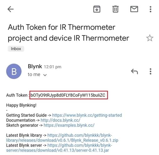
Go to the setting and click on Send Email. The authentication code will be sent to the Mail. This authentication code will be used in the ESP8266 Code.
Source Code/Program
The Source Code/Program for NodeMCU ESP8266, MLX90614 & Blynk is written on Arduino IDE. The code requires MLX90614 Library for compilation. Apart from the MLX90614 Library, it also requires Blynk Library. So first download the libraries from the link below and add it to the Arduino IDE Library folder.
- Download Adafruit MLX90614 Library
- Download Blynk Library
|
1 2 3 |
char auth[] = "bOTy***********115buIiZC"; // Blynk Auth Token char ssid[] = "***************"; // Your WiFi SSID char pass[] = "***************"; // Your WiFi password |
Change the Wifi SSID & Password. Also, insert the Authentication Token that you got from the Blynk. I have added a calibration factor of 2.36 to calibrate the object temperature reading. You can add your own in the code part.
The complete source code is given below.
|
1 2 3 4 5 6 7 8 9 10 11 12 13 14 15 16 17 18 19 20 21 22 23 24 25 26 27 28 29 30 31 32 33 34 35 36 37 38 39 40 41 42 43 44 45 46 47 48 49 50 51 52 53 54 55 56 57 58 59 60 61 62 63 64 65 66 67 68 69 70 71 72 73 74 75 76 77 78 79 80 81 82 83 84 85 86 87 |
#include <Wire.h> #include <Adafruit_MLX90614.h> #include <Adafruit_GFX.h> #include <Adafruit_SSD1306.h> #define BLYNK_PRINT Serial #include <Blynk.h> #include <ESP8266WiFi.h> #include <BlynkSimpleEsp8266.h> #define SCREEN_WIDTH 128 // OLED display width, in pixels #define SCREEN_HEIGHT 64 // OLED display height, in pixels #define OLED_RESET -1 // Reset pin # (or -1 if sharing Arduino reset pin) Adafruit_SSD1306 display(SCREEN_WIDTH, SCREEN_HEIGHT, &Wire, OLED_RESET); Adafruit_MLX90614 mlx = Adafruit_MLX90614(); double temp_amb; double temp_obj; double calibration = 2.36; char auth[] = "bOTyO9tRJyp8d0FLY8CoFyW115buIiZC"; // You should get Auth Token in the Blynk App. char ssid[] = "Alexahome"; // Your WiFi credentials. char pass[] = "loranthus"; void setup() { Serial.begin(9600); mlx.begin(); //Initialize MLX90614 display.begin(SSD1306_SWITCHCAPVCC, 0x3C); //initialize with the I2C addr 0x3C (128x64) Blynk.begin(auth, ssid, pass); Serial.println("Temperature Sensor MLX90614"); display.clearDisplay(); display.setCursor(25,15); display.setTextSize(1); display.setTextColor(WHITE); display.println(" Thermometer"); display.setCursor(25,35); display.setTextSize(1); display.print("Initializing"); display.display(); delay(2500); } void loop() { //Reading room temperature and object temp //for reading Fahrenheit values, use //mlx.readAmbientTempF() , mlx.readObjectTempF() ) Blynk.run(); temp_amb = mlx.readAmbientTempC(); temp_obj = mlx.readObjectTempC(); //Serial Monitor Serial.print("Room Temp = "); Serial.println(temp_amb); Serial.print("Object temp = "); Serial.println(temp_obj); display.clearDisplay(); display.setCursor(25,0); display.setTextSize(1); display.setTextColor(WHITE); display.println(" Temperature"); display.setCursor(10,20); display.setTextSize(1); display.print("Ambient: "); display.print(temp_amb); display.print((char)247); display.print("C"); display.setCursor(10,40); display.setTextSize(1); display.print("Object: "); display.print(temp_obj + calibration); display.print((char)247); display.print("C"); display.display(); Blynk.virtualWrite(V1, temp_amb); Blynk.virtualWrite(V2, (temp_obj + calibration)); delay(1000); } |
Testing IoT Based IR Thermometer on Blynk
After uploading the code, you can start testing the IoT Based IR Thermometer. As soon as you upload the code, the 0.96″ OLED Display starts displaying the Ambient Temperature as well as Object Temperature.

You can then check your Blynk Application. The Blynk application will display both the temperature value in gauge format as shown in the image below.

So this is how you can build your own IoT Based IR Thermometer using MLX90614, ESP8266 & Blynk Application. This project can be made better by adding an Ultrasonic Sensor to the circuit and code for detecting the proper distance. You can use any other IoT Platform like Thingspeak, Ubidots, or Adafruit IO in case you don’t want to use Blynk.

A Thermal Camera can be made using a similar sensor Thermal Sensor called AMG8833 Thermal Image Sensor & Raspberry Pi 4.


