

Overview
In this project, we will monitor the sensor data wirelessly using the NRF24L01 STM32 Board & ESP32 Wifi Module. We will first make a Wireless Sensor Node. A sensor node is made up of four basic components such as sensing unit, processing unit, transceiver unit, and a power unit. The Sensing unit can be made up of any Sensor. I am using the BME280 Barometric Pressure Sensor. The processing unit is the STM32F103C Microcontroller and the transceiver unit is the NRF24L01 2.4 GHz Wireless transceiver Module which works as a transmitter unit. While considering the power unit, the device can be powered up using 3.7V Lithium-Ion Battery.
We will make Wifi Gateway using ESP32 Wifi Module & NRF24L01 Module. An IoT gateway performs several critical functions from translating protocols to encrypting, processing, managing, and filtering data. If you imagine an IoT ecosystem, a gateway sits between devices and sensors to communicate with the cloud. In this project, the gateway collects the sensor data from multiple sensor nodes, and using the wifi network it uploads the data to the cloud. The cloud server that we are using here is the Thingspeak Server. ThingSpeak is an open-source Internet of Things application and API to store and retrieve data from things using the HTTP and MQTT protocol over the Internet or via a Local Area Network.
In one of our previous project we made a gateway using ESP8266 & NRF24L01 & Sensor Node using Arduino & NRF24L01. You can check the project here: NRF24L01 Gateway + Node
Bill of Materials
All the components required for making the gateway and sensor node is listed below. You can purchase all of the components from Amazon.
| S.N. | Components Name | Quantity | Purchase Links |
|---|---|---|---|
| 1 | ESP32 Board | 1 | Amazon | AliExpress |
| 2 | STM32 Microcontroller | 2 | Amazon | AliExpress |
| 3 | NRF24L01 PA+LNA | 2 | Amazon | AliExpress |
| 4 | BME280 Barometric Pressure Sensor | 1 | Amazon | AliExpress |
| 5 | Power Supply 5V | 2 | Amazon | AliExpress |
| 6 | Connecting Wires | 20 | Amazon | AliExpress |
| 7 | Breadboard | 1 | Amazon | AliExpress |
NRF24L01 Module

The nRF24L01 is a wireless transceiver module, i.e. each module can both send & receive data. It works within the frequency of 2.4GHz. This frequency falls under the ISM band and is legal to use in most countries for engineering projects. The modules when operated efficiently can cover a distance of 100 meters.
The module operates at 3.3V but its SPI pins are 5V tolerable. Each module has an address range of 125 and every module can communicate with 6 other modules hence mesh networking can be established with this module. The NRF24L01 module works with the help of SPI communications hence you can use NRF24L01 with any microcontroller with SPI Pins like STM32 or Arduino Boards.
Sensor Node Using NRF24L01 & STM32F103C
Let us see the Sensor Node Circuit. We can use any microcontroller with NRF24L01 for designing a Sensor Node. For example, STM32F103C Bluepill Board is the best option. Apart from the microcontroller, you can use any sensor and interface it with STM32 Board. I prefer BME280 Barometric Pressure Sensor for demonstration purpose.
The connection between STM32F103C Board, NRF24L01 Wireless Transceiver Module & BME280 Sensor is given below.

NRF24L01 CSN ………………………………………… PA4 of STM32F103C
NRF24L01 MOSI ………………………………………… PA7 of STM32F103C
NRF24L01 GND ………………………………………… GND of STM32F103C
NRF24L01 CE ………………………………………… PB0 of STM32F103C
NRF24L01 SCK ………………………………………… PA5 of STM32F103C
NRF24L01 MISO ………………………………………… PA6 of STM32F103C
You can also design a simple Sender and Receiver Circuit with a pair of NRF24L01 & STM32 Board. Check it here: Interfacing NRF24L01 Transceiver Module with STM32.
WiFi Gateway Using NRF24L01 & ESP32
The Gateway receives the data from the single or multiple Sensor Node using the NRF24L01 Transceiver Module. After receiving data it uploads the data to Server. For establishing a connection with the Server, the WiFi Network can be used. The ESP32 along with NRF24L01 is best preferred for designing the WiFi Gateway.
The connection between ESP32 Board & NRF24L01 Wireless Transceiver Module is given below.

NRF24L01 CSN ………………………………………… D5 of ESP32
NRF24L01 MOSI ………………………………………… D23 of ESP32
NRF24L01 GND ………………………………………… GND of ESP32
NRF24L01 CE ………………………………………… D4 of ESP32
NRF24L01 SCK ………………………………………… D18 of ESP32
NRF24L01 MISO ………………………………………… D19 of ESP32
Project PCB Gerber File & PCB Ordering Online
If you don’t want to assemble the circuit on breadboard and you want PCB for the project, then here is the PCB for you. The PCB Board for the ESP32 NRF24L01 Gateway & STM32 NRF24L01 Node is designed using EasyEDA online Circuit Schematics & PCB designing tool. The image of the Sender PCB is given below.


The Gerber File for the PCB is given below. You can simply download the Gerber File and order the PCB from ALLPCB at 1$ only.
- Download Gerber File for Node PCB: Sender PCB
- Download Gerber File for Gateway PCB: Receiver PCB
You can use this Gerber file to order high quality PCB for this project. To do that visit the ALLPCB official website by clicking here: https://www.allpcb.com/.

You can now upload the Gerber File by choosing the Quote Now option. From these options, you can choose the Material Type, Dimensions, Quantity, Thickness, Solder Mask Color and other required parameters.

After filling all details, select your country and shipping method. Finally you can place the order.
Library Installation
1. BME280 Library
The BME280 library provides a library for reading and interpreting Bosch BME280 environmental sensor data over I2C, SPI or Sw SPI. It reads the temperature, humidity, and pressure by including environment calculations.
2. NRF24L01 Library
The STM32 Board doesn’t support nRF24L01 RadioHead Library (#include <RH_NRF24.h>). Hence we need to use RF24 Library. This library is designed to be maximally compliant with the intended operation of the chip & built against the standard SPI library. You can download the library from the following Github link. Add the library to the Arduino IDE.
Setting Up Thingspeak Server
ThingSpeak is an IoT analytics platform service that allows you to aggregate, visualize, and analyze live data streams in the cloud. You can send data to ThingSpeak from your devices, create instant visualization of live data, and send alerts.
We need to Setup Thingspeak dashboard to receive the data and display in graphical format. You can visit Thingspeak and create an account here.
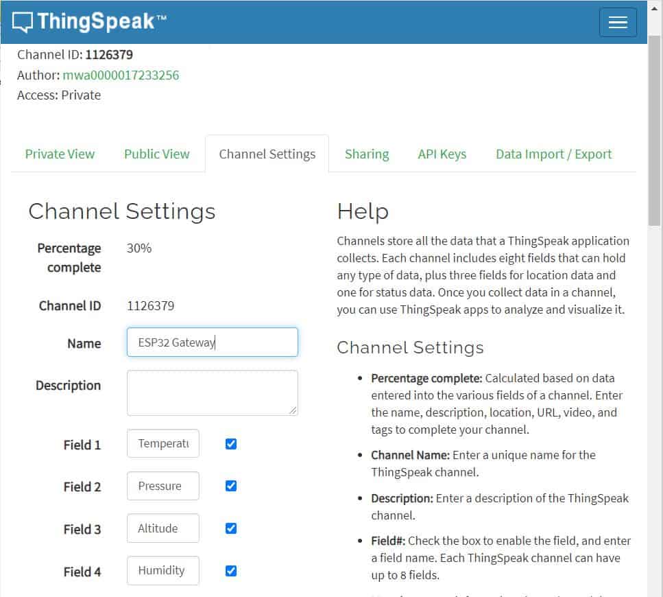
Create a New Channel with the following Parameters as shown in the image below. After filling all these details, click on the Save channel.
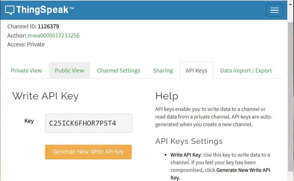
Go to the API Key and copy the Write API Key. The API key is required in the Gateway Code.
Source Code/Program for Sensor Node
|
1 2 3 4 5 6 7 8 9 10 11 12 13 14 15 16 17 18 19 20 21 22 23 24 25 26 27 28 29 30 31 32 33 34 35 36 37 38 39 40 41 42 43 44 45 46 47 48 49 50 51 52 53 54 55 56 57 58 59 60 61 62 63 64 65 66 67 68 69 70 71 72 73 74 75 76 77 78 79 80 81 82 83 84 |
#include <SPI.h> #include <Wire.h> #include <Adafruit_Sensor.h> #include <Adafruit_BME280.h> #include <nRF24L01.h> #include <RF24.h> RF24 radio(PB0, PA4); // CE, CSN on Blue Pill const uint64_t address = 0xF0F0F0F0E1LL; int counter = 0; float temperature; float humidity; float altitude; float pressure; #define SEALEVELPRESSURE_HPA (1013.25) Adafruit_BME280 bme; struct MyData { int counter; float temperature; float humidity; float altitude; float pressure; }; MyData data; void setup() { Serial.begin(115200); radio.begin(); //Starting the Wireless communication radio.openWritingPipe(address); //Setting the address where we will send the data radio.setPALevel(RF24_PA_MIN); //You can set it as minimum or maximum depending on the distance between the transmitter and receiver. radio.stopListening(); //This sets the module as transmitter if (!bme.begin(0x76)) { Serial.println("Could not find a valid BME280 sensor, check wiring!"); while (1); } } void loop() { data.counter = counter; data.temperature = bme.readTemperature(); data.pressure = bme.readPressure() / 100.0F; data.altitude = bme.readAltitude(SEALEVELPRESSURE_HPA); data.humidity = bme.readHumidity(); Serial.print("Packet No. = "); Serial.println(data.counter); Serial.print("Temperature = "); Serial.print(data.temperature); Serial.println("*C"); Serial.print("Pressure = "); Serial.print(data.pressure); Serial.println("hPa"); Serial.print("Approx. Altitude = "); Serial.print(data.altitude); Serial.println("m"); Serial.print("Humidity = "); Serial.print(data.humidity); Serial.println("%"); Serial.println(); radio.write(&data, sizeof(MyData)); Serial.println("Data Packet Sent"); Serial.println(""); counter++; delay(5000); } |
Source Code/Program for ESP32 Wifi Gateway
Before uploading the code, make changes to the Wifi SSID & Password. Also replace the Thingspeak API Key with your own API Key.
|
1 2 3 4 5 6 7 8 9 10 11 12 13 14 15 16 17 18 19 20 21 22 23 24 25 26 27 28 29 30 31 32 33 34 35 36 37 38 39 40 41 42 43 44 45 46 47 48 49 50 51 52 53 54 55 56 57 58 59 60 61 62 63 64 65 66 67 68 69 70 71 72 73 74 75 76 77 78 79 80 81 82 83 84 85 86 87 88 89 90 91 92 93 94 95 96 97 98 99 100 101 102 103 104 105 106 107 108 109 110 111 112 113 114 115 116 117 |
#include <WiFi.h> #include <SPI.h> #include <nRF24L01.h> #include <RF24.h> String apiKey = "C25ICK6FHOR7PST4"; const char* ssid = "Alexahome"; const char* password = "loranthus"; const char* server = "api.thingspeak.com"; RF24 radio(4, 5); const uint64_t address = 0xF0F0F0F0E1LL; struct MyData { int counter; float temperature; float humidity; float altitude; float pressure; }; MyData data; WiFiClient client; void setup() { Serial.begin(115200); radio.begin(); Serial.println("Receiver Started...."); Serial.print("Connecting to "); Serial.println(ssid); Serial.println(); WiFi.begin(ssid, password); while (WiFi.status() != WL_CONNECTED) { delay(500); Serial.print("."); } Serial.println(""); Serial.println("WiFi connected"); radio.openReadingPipe(0, address); //Setting the address at which we will receive the data radio.setPALevel(RF24_PA_MIN); //You can set this as minimum or maximum depending on the distance between the transmitter and receiver. radio.startListening(); //This sets the module as receiver } int recvData() { if ( radio.available() ) { radio.read(&data, sizeof(MyData)); return 1; } return 0; } void loop() { if(recvData()) { Serial.println("Data Received:"); Serial.print("Packet No. = "); Serial.println(data.counter); Serial.print("Temperature = "); Serial.print(data.temperature); Serial.println("*C"); Serial.print("Pressure = "); Serial.print(data.pressure); Serial.println("hPa"); Serial.print("Approx. Altitude = "); Serial.print(data.altitude); Serial.println("m"); Serial.print("Humidity = "); Serial.print(data.humidity); Serial.println("%"); Serial.println(); if (client.connect(server, 80)) { String postStr = apiKey; postStr += "&field1="; postStr += String(data.temperature); postStr += "&field2="; postStr += String(data.pressure); postStr += "&field3="; postStr += String(data.altitude); postStr += "&field4="; postStr += String(data.humidity); postStr += "\r\n\r\n\r\n\r\n"; client.print("POST /update HTTP/1.1\n"); client.print("Host: api.thingspeak.com\n"); client.print("Connection: close\n"); client.print("X-THINGSPEAKAPIKEY: " + apiKey + "\n"); client.print("Content-Type: application/x-www-form-urlencoded\n"); client.print("Content-Length: "); client.print(postStr.length()); client.print("\n\n"); client.print(postStr); delay(1000); Serial.println("Data Sent to Server"); } client.stop(); } } |
Result: ESP32+ NRF24L01 Wifi Gateway with STM32+ NRF24L01 Node

After assembling the Sensor Node & Gateway on a breadboard, you can upload the above codes to the respective nodes.
Soon after the code is uploaded, you can open the respective Serial Monitor.
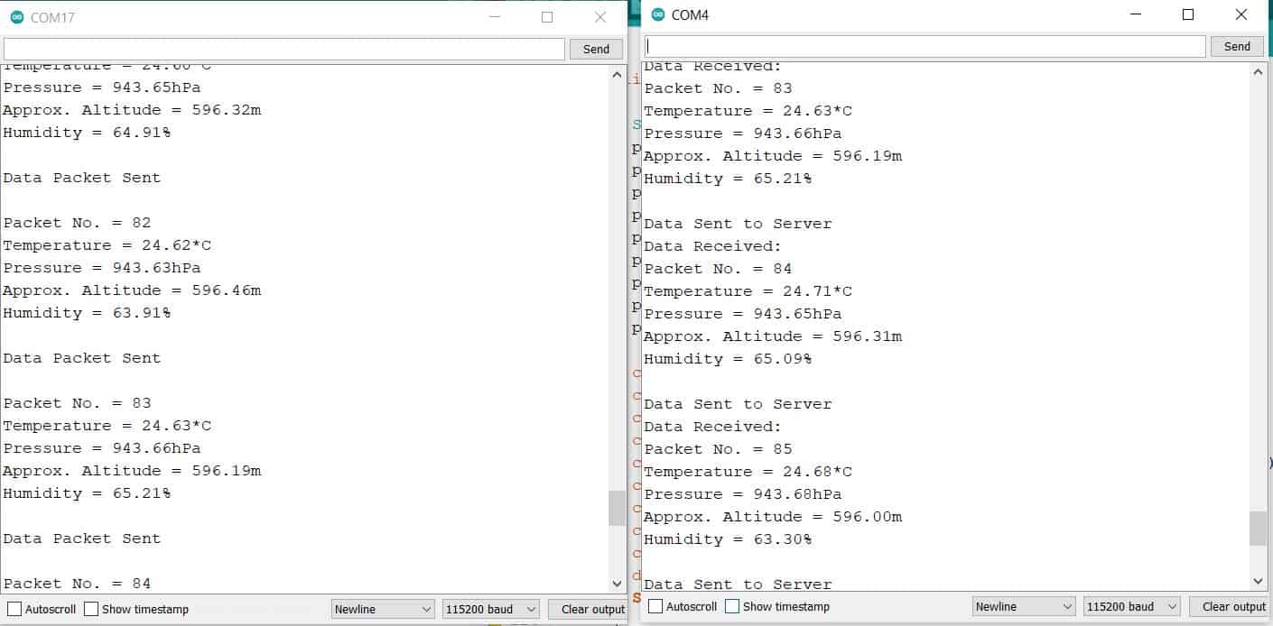
The BME280 Sensor Data from Transmitter is received by Receiver/Gateway. The Gateway displays the received data like temperature, humidity, pressure, and altitude on the Serial Monitor.
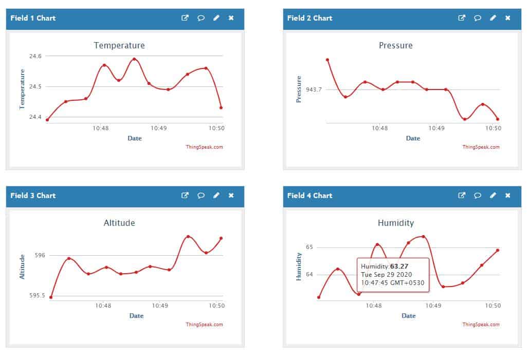
Similarly you can monitor the data online on Thingspeak Server. For that, go to the private view of Thingspeak Server. The data will be logged on after the interval of 15 seconds. To make the device more better, you can implement the Sleep Mode feature and change Data Sending Interval.
 & Live Dashboard")


4 Comments
Hello! Great project! The sender works fine on Arduino Pro Mini.
I tried to make the reciever work on the esp32 but with no luck (WIFI, thingspeak part work only I’m having trouble with nrf24l01).
First of all I used TMRh20’s RF24 library https://github.com/nRF24/RF24
because with the one you linked didnt compile to esp32 board.
The program started but the recvData() returns with 1 even if theres no sender plugged in, and also it shows 0 values if so.
Could you confirm that this is working on your side?
Thank you!
The circuit is tested along with the code. It works perfectly.
SIR CAN WE GET THE HEX FILE OF THE CODE??
use this modified revision of RF24 lib (works with esp32) https://github.com/nhatuan84/RF24