


Overview
In this project, we will build our own Thermal Imaging Camera with MLX90640 & Raspberry Pi. The MLX90640 far-infrared camera is an array of 768 (32×24) thermal sensors that can detect temperatures from -40 to 300°C with approximately 1°C accuracy.
Earlier we build a Thermal Camera using AMG8833 & Raspberry Pi Board. The AMG8833 has a lower resolution of 8×8 pixels, totaling 64 thermal detectors. But the MLX90640 sensor offers a higher resolution of 32×24 pixels, which translates to 768 individual thermal detectors. This higher resolution provides more detailed thermal images. The AMG8833 offers a lower refresh rate of 10 Hz, making it less ideal for monitoring fast-changing thermal events, while the MLX90640 supports a higher refresh rate of up to 64 Hz for smoother thermal video capture.
This DIY Thermal Imaging Camera using MLX90640 & Raspberry Pi uses a Python Code and multiple Python libraries like Numpy and Matplotlib for visualization of Thermal images in a 7-inch HDMI LCD Screen. Thus building a thermal imaging camera using the Raspberry Pi and the MLX90640 is a fun and affordable project that can be done by anyone with basic electronic skills. Whether your aim is to spot temperature variations around the house, identify heat escapes in building structures, Fever Detection System, or merely take unique infrared photos on MLX90640 Webserver, this project provides an excellent starting point.
Bill of Materials
Following are the list of components required to build this DIY Thermal Imaging Camera. You can purchase all the components from Amazon or the SunFounder.
| S.N. | Components | Quantity | Purchase Link |
|---|---|---|---|
| 1 | Raspberry Pi 4 | 1 | Amazon | SunFounder |
| 2 | MLX90640 Thermal Image Sensor | 1 | Amazon | AliExpress |
| 3 | TS-Pro 7 inch LCD Display | 1 | Amazon | SunFounder |
| 4 | SD Card 16/32 GB | 1 | Amazon | SunFounder |
| 5 | 5V, 3A DC Adapter for RPi | 1 | Amazon | SunFounder |
| 6 | UPS Power Supply with Battery (Optional) | 1 | Amazon | SunFounder |
| 7 | Mouse & Keyboard (Optional) | 1 | Amazon | SunFounder |
MLX90640 32×24 IR Array Temperature Sensor
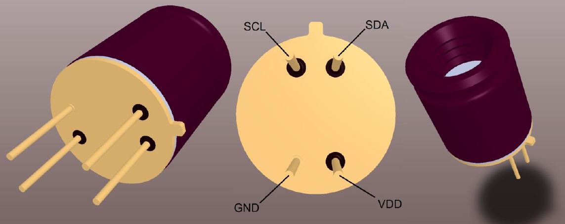
The MLX90640 from Melexis is a small size, non-contact, and low cost far-infrared thermal sensor array that integrates 768 (32×24) thermal sensors into a compact and standard 4-lead TO39 package.
This sensor is capable of capturing detailed thermal images by measuring the infrared radiation emitted by objects in its field of view, translating it into temperature readings ranging from -40°C to 300°C.

The sensor achieves a high degree of accuracy, maintaining approximately ±1°C across its operational range. Furthermore, the MLX90640 includes additional functionalities like an ambient temperature sensor and a supply voltage sensor, enhancing its precision and reliability. Data from the IR sensors, as well as the ambient and supply voltage measurements, are stored in internal RAM and can be accessed via an I2C interface.
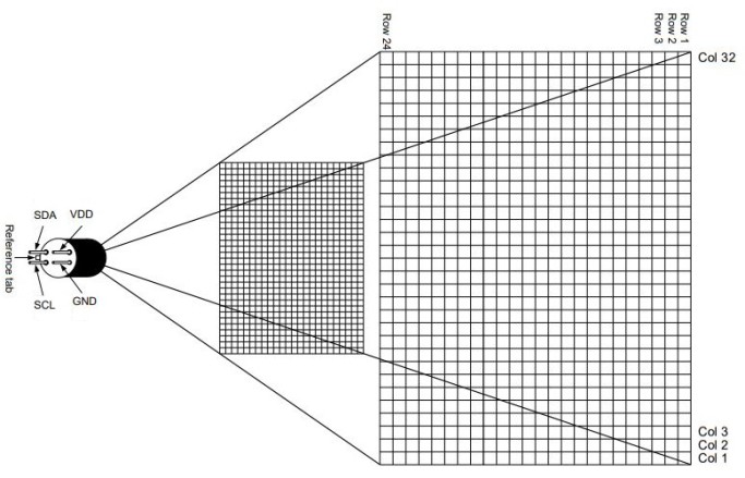
The MLX90640 thermal camera features a 32×24 array, totaling 768 individual far-infrared pixels. Each pixel captures temperature data, allowing for detailed thermal imaging and accurate temperature measurements across the sensor’s field of view.
The MLX90640 is not only functional but also user-friendly, tailored for hobbyists and professionals alike. It supports both 3.3V and 5V operating voltages and communicates through a configurable I2C interface that can reach data rates up to 1MHz. This sensor is compatible with platforms like Arduino, Raspberry Pi, or STM32.
The sensor’s capability to adjust the frame rate from 0.5 to 64Hz allows users to fine-tune its performance based on specific application requirements, whether it’s tracking fast-moving objects or conducting detailed thermal evaluations over a slower period. Refer to MLX90640 Datasheet for more information about this Thermal Camera.
Features and Benefits
- Small size, low cost 32×24 pixels IR array
- Easy to integrate
- Industry standard four lead TO39 package
- Factory calibrated
- Noise Equivalent Temperature Difference (NETD): 0.1K RMS @1Hz refresh rate
- I2C compatible digital interface
- Programmable refresh rate 0.5Hz…64Hz
- 3.3V supply voltage
- Current consumption is less than 23mA
- 2 FOV options – 55°x35° and 110°x75°
- Operating temperature -40°C ÷ 85°C
- Target temperature -40°C ÷ 300°C
- Complies with RoHS regulations
Applications of MLX90640
- High-precision non-contact temperature measurements
- Intrusion / Movement detection
- Presence detection / Person localization
- Temperature sensing element for intelligent building air conditioning
- Thermal Comfort sensor in automotive Air Conditioning control system
- Microwave ovens
- Industrial temperature control of moving parts
- Visual IR thermometers
Pinout of MLX90640
The MLX90640 Thermal Camera has 4 pins that need to be connected to the controller and currently supports the Raspberry Pi, STM32F405R, and ESP32 series.
- VCC: Power supply pin, should be connected to the control 3.3V or 5V power supply.
- GND: Ground pin, corresponds to the connection of the ground (GND).
- SDA: Data pin for I2C communication, connected to the GPIO of the controller.
- SCL: Clock pin for I2C communication, connected to the GPIO of the controller
Certain variants of the MLX90640 thermal camera module are equipped to support the UART communication protocol in addition to the standard I2C interface. This feature allows for greater flexibility in integrating the sensor with a wider range of microcontrollers and systems that might prefer UART for simplicity or specific application requirements.
Measurement Distance & FOV
The MLX90640 thermal sensor offers a field of view (FOV) of either 55 degrees or 110 degrees, depending on the model.
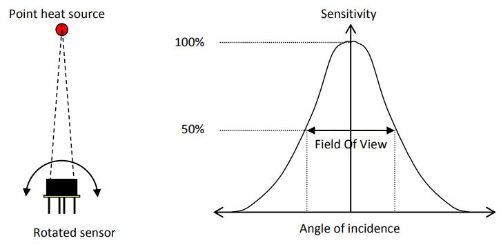
The Field of View (FOV) of the MLX90640 thermal sensor is defined by the 50% radiation signal received by its thermopile and is oriented along the sensor’s main axis. It measures a weighted average temperature of objects within this FOV, requiring full coverage of the target within the FOV for accurate readings.
Variants of MLX90640
The MLX90640 is an infrared thermal sensor array that comes in two variants: MLX90640BAA and MLX90640BAB.
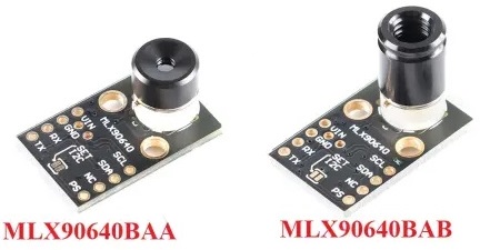
- MLX90640BAA: It has a wider field of view of 110° x 75°. This variant is suitable for applications where a larger area needs to be observed at once, such as broad area surveillance or room occupancy sensing.
- MLX90640BAB: It has a narrower field of view of 55° x 35°. This variant is better for focused thermal measurements, making it ideal for applications like electronic device thermal testing or targeted object detection.
MLX90640 Communication Protocol
The MLX90640 utilizes the I2C communication protocol with support for FM+ mode, allowing up to 1MHz clock frequency. It operates solely as a slave device on the I2C bus. Both SDA and SCL ports are 5V tolerant, enabling direct connection to a 5V I2C network. The sensor’s slave address is programmable, supporting up to 127 different addresses.

Each session starts with a START condition (SDA transitions from HIGH to LOW while SCL is HIGH) and ends with a STOP condition (SDA transitions from LOW to HIGH while SCL is HIGH).

The device is addressed using a 7-bit slave address followed by a Read/Write bit, where HIGH indicates a read operation and LOW indicates a write operation. Each byte transfer is followed by an acknowledgment (ACK), where the receiver pulls the SDA line low to indicate receipt.
MLX90640 Refresh Rate
The MLX90640’s refresh rate can be configured via “Control register 1” (0x800D), with options ranging from 0.5Hz to 64Hz, corresponding to data updates from every 2 seconds to every 15.6 milliseconds.
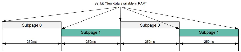
Settings can be permanently saved in the EEPROM at address 0x240C to avoid reconfiguration after power cycling. Accurate temperature calculations require reading from both of the sensor’s alternating subpages.
Hardware Setup for MLX90640 & Raspberry Pi
Let us interface the MLX90640 Thermal Imaging Camera with Raspberry Pi 4. The connection is very simple as MLX90640 requires I2C Communication protocol to communicate with Raspberry Pi 4.
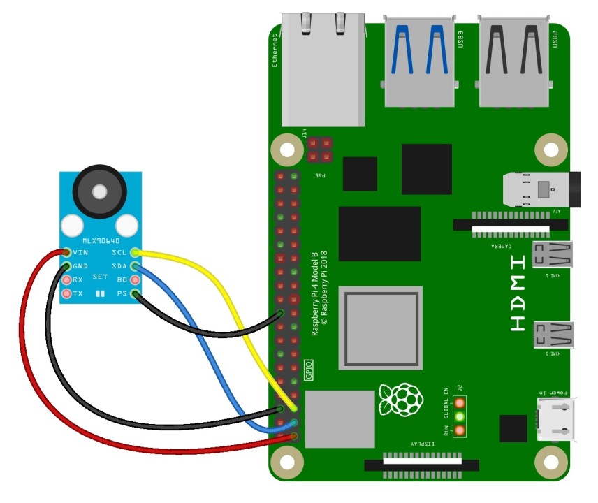
- VCC: Connect the VCC pin of the MLX90640 to one of the 3.3V pins on the Raspberry Pi.
- GND: Connect the GND pin of the MLX90640 to one of the ground pins on the Raspberry Pi.
- SDA: Connect the SDA pin of the MLX90640 to the SDA pin on the Raspberry Pi GPIO (Pin 3).
- SCL: Connect the SCL pin of the MLX90640 to the SCL pin on the Raspberry Pi GPIO (Pin 5).
Note: For one of the module with UART Module Pins, connect PS to GND to enable I2C Communication.
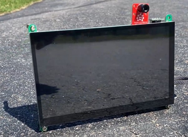
To visualize the Thermal images, you need a portable HMI Display. In my case, I used a TS-7 Pro 7-inch HMI Display from SounFounder.

With a resolution of 1024×600 pixels, it offers a convenient way to display content and interact with the Raspberry Pi. The Raspberry Pi fits perfectly on the Display.
Similarly, we also need a power supply unit for the Raspberry Pi & the display unit. I used a PiPower UPS Supply from SunFounder, which is a special portable UPS Supply designed for Raspberry Pi 4.

The PCB Board comes along with a 7.4V, 2000mAh Rechargeable Battery.

Here is how our device looks after the PiPower Portable UPS Supply is connected to the Raspberry Pi.
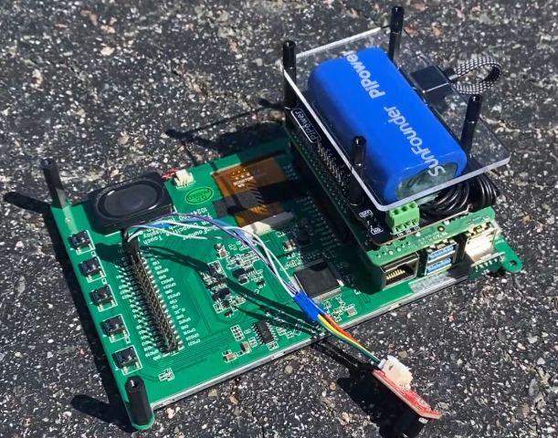
You can slide the Power button on the PiPower PCB and you will see the Raspberry Pi Booting up immediately.
Preparing a Raspberry Pi for the MLX90640 Usage
First, install the Raspbian operating system on your Raspberry Pi. If you have a HDMI Monitor, you can directly start programming. In my case, I have connected my Raspberry Pi to the VNC viewer via SSH terminal. This mean I can program my Raspberry Pi remotely.
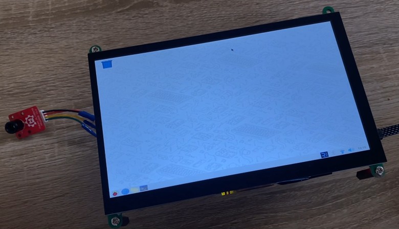
Open your Raspberry Pi Terminal. Let up first start with updating the Raspberry Pi. The following command updates the list of available packages and their versions.
|
1 |
sudo apt-get update |
Then run the upgrade command to install newer versions of the packages you have.
|
1 |
sudo apt-get upgrade |
Then install the matplotlib library for creating static, interactive, and animated visualizations in Python.
|
1 |
sudo pip3 install matplotlib |
Installs the SciPy library. This library is used for scientific and technical computing.
|
1 |
sudo pip3 install scipy |
The following command will install NumPy, a library for large, multi-dimensional arrays and matrices, along with a large collection of mathematical functions to operate on these arrays.
|
1 |
sudo pip3 install numpy |
Then install the python-smbus package, necessary for accessing the I2C bus via Python.
|
1 |
sudo apt-get install -y python-smbus |
The following command will installs i2c-tools, useful for probing and debugging I2C communications.
|
1 |
sudo apt-get install -y i2c-tools |
Now open the Raspberry Pi’s boot configuration file in nano text editor using the following command.
|
1 |
sudo nano /boot/config.txt |

Add dtparam=i2c_arm=on, i2c_arm_baudrate=400000 to enable the I2C interface and set the baud rate for faster data transfer.
Now Reboot the Raspberry Pi to apply changes.
|
1 |
sudo reboot |
Once the Raspberry Pi restarts, run the following command to scan and display devices connected on the I2C bus 1, helpful for verifying connectivity.
|
1 |
sudo i2cdetect -y 1 |
The output 0x33 indicates that there is a device detected at the I2C address 0x33 on the I2C bus 1 of your Raspberry Pi. This address corresponds to a device that is actively communicating via I2C, which is the MLX90640 thermal camera sensor.
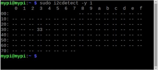
This confirms that the MLX90640 sensor is properly connected and recognized by your Raspberry Pi.
I reviewed the datasheets for the sensor from Melexis, which contain complex mathematical equations and numerous calculations. Understanding all these mathematical details may seem daunting, almost requiring a PhD in Physics or Mathematics. Fortunately, Adafruit has developed a library that handles all these complex calculations, significantly simplifying the process for users.
Run the following command now.
|
1 |
sudo pip3 install RPI.GPIO adafruit-blinka |
This install RPi.GPIO for GPIO pin management on the Raspberry Pi and Adafruit Blinka, a compatibility layer to allow CircuitPython libraries to run on Raspberry Pi.
Finally we need to install the Adafruit MLX90640 Library. Therefore run the following command.
|
1 |
sudo pip3 install adafruit-circuitpython-mlx90640 |
This sequence of commands sets up your Raspberry Pi for using the MLX90640 sensor, ensuring all necessary libraries and tools are installed and configured correctly.
Python Script for Capturing Average Temperature Readings
Since, setting up the Raspberry Pi is completed, we need to move to the programming part.
Open your Thonny IDE and paste the following Python Script to the editor window.
|
1 2 3 4 5 6 7 8 9 10 11 12 13 14 15 16 17 18 19 20 21 22 23 24 25 26 27 28 29 30 31 32 33 |
import time import board import busio import numpy as np import adafruit_mlx90640 def main(): # Setup I2C connection i2c = busio.I2C(board.SCL, board.SDA, frequency=400000) mlx = adafruit_mlx90640.MLX90640(i2c) mlx.refresh_rate = adafruit_mlx90640.RefreshRate.REFRESH_2_HZ frame = np.zeros((24 * 32,)) # Initialize the array for all 768 temperature readings while True: try: mlx.getFrame(frame) # Capture frame from MLX90640 average_temp_c = np.mean(frame) average_temp_f = (average_temp_c * 9.0 / 5.0) + 32.0 print(f"Average MLX90640 Temperature: {average_temp_c:.1f}C ({average_temp_f:.1f}F)") time.sleep(0.5) # Adjust this value based on how frequently you want updates except ValueError as e: print(f"Failed to read temperature, retrying. Error: {str(e)}") time.sleep(0.5) # Wait a bit before retrying to avoid flooding with requests except KeyboardInterrupt: print("Exiting...") break except Exception as e: print(f"An unexpected error occurred: {str(e)}") if __name__ == "__main__": main() |
This Python script sets up an I2C connection to continuously read and display the average temperature from an MLX90640 thermal camera sensor at a 2 Hz refresh rate.
Run this script and you will see the terminal displaying the temperature values.
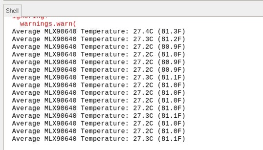
This testing confirms the working of your MLX90640 Sensor. To observe temperature values up to 300 degrees, you can place a hot object near the sensor.
Visualizing Thermal Image with the MLX90640 & Raspberry Pi
To visualize thermal images using matplotlib and numpy, I utilized a Python code from a GitHub repository by Maker Portal. I modified the Python Script to meet my specific needs.
The thermal data from the MLX90640 sensor is read and visualized using the ‘imshow‘ function, which plots the data with the origin at the top-left, requiring data to be horizontally flipped for accurate representation of the sensor’s spatial output.
|
1 2 3 4 5 6 7 8 9 10 11 12 13 14 15 16 17 18 19 20 21 22 23 24 25 26 27 28 29 30 31 32 33 34 35 36 37 38 39 40 41 42 43 |
import time import board import busio import numpy as np import adafruit_mlx90640 import matplotlib.pyplot as plt i2c = busio.I2C(board.SCL, board.SDA) mlx = adafruit_mlx90640.MLX90640(i2c) mlx.refresh_rate = adafruit_mlx90640.RefreshRate.REFRESH_4_HZ # Set to a feasible refresh rate plt.ion() fig, ax = plt.subplots(figsize=(12, 7)) therm1 = ax.imshow(np.zeros((24, 32)), vmin=0, vmax=60) cbar = fig.colorbar(therm1) cbar.set_label('Temperature [$^{\circ}$C]', fontsize=14) frame = np.zeros((24*32,)) t_array = [] max_retries = 5 while True: t1 = time.monotonic() retry_count = 0 while retry_count < max_retries: try: mlx.getFrame(frame) data_array = np.reshape(frame, (24, 32)) therm1.set_data(np.fliplr(data_array)) therm1.set_clim(vmin=np.min(data_array), vmax=np.max(data_array)) fig.canvas.draw() # Redraw the figure to update the plot and colorbar fig.canvas.flush_events() plt.pause(0.001) t_array.append(time.monotonic() - t1) print('Sample Rate: {0:2.1f}fps'.format(len(t_array)/np.sum(t_array))) break except ValueError: retry_count += 1 except RuntimeError as e: retry_count += 1 if retry_count >= max_retries: print(f"Failed after {max_retries} retries with error: {e}") break |
The MLX90640 sensor I’m using supports a maximum refresh rate of 64Hz, but due to the limitations of my Raspberry Pi, I’ve set it to 4Hz.
Operating the I2C bus at high speeds like 1 Mbit/s for demanding applications such as real-time thermal imaging with the MLX90640 sensor can lead to increased power consumption and heat generation. It’s crucial to ensure adequate cooling for the Raspberry Pi to prevent thermal throttling or damage. Proper ventilation or active cooling solutions, such as heatsinks or fans, are recommended to maintain stable operation and prevent overheating when pushing the I2C communication speed beyond the typical 400 kbit/s.
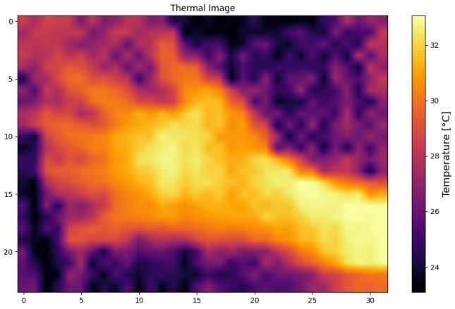
When you run this modified code, it displays thermal images as shown in the image below.
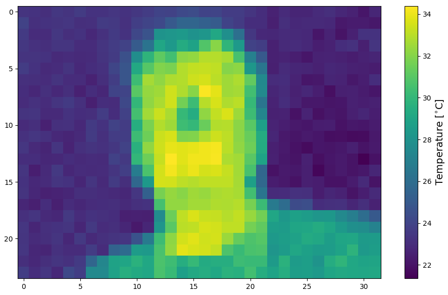
You can interact with MLX90640 Thermal Camera by positioning yourself or moving your hand in front of the sensor.
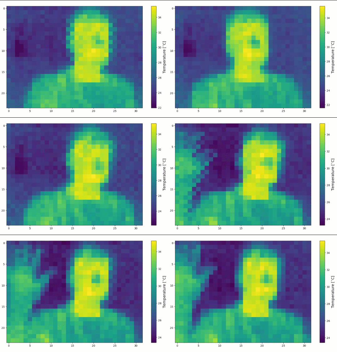
This results in a pixelated view of the thermal data at four frames per second. Although this provides a basic visualization, the images are quite noisy and require further processing to enhance clarity and smoothness.
Real-Time Data Interpolation using the MLX90640
Interpolation is a computational technique in Python used to estimate unknown values by calculating between two known values.
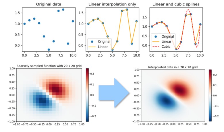
This approach is particularly useful in improving the quality of thermal images captured with MLX90640 sensor. By implementing interpolation, we can enhance the resolution and visual clarity of the resulting thermal images.
In the updated Python script, interpolation is applied to data from the MLX90640 thermal camera sensor, enabling it to display a continuously updated, live thermal video stream.
The Python script fetches the 24×32 pixel thermal data, which is then visualized in real time using Matplotlib’s imshow function. To align with the sensor’s orientation, the data array is horizontally flipped before display. The visualization includes a dynamically adjustable color map for temperature ranges, enhancing image clarity and understanding.
To handle the data processing efficiently, the script utilizes an interactive Matplotlib plot (plt.ion()), which is updated continuously within a loop.
|
1 2 3 4 5 6 7 8 9 10 11 12 13 14 15 16 17 18 19 20 21 22 23 24 25 26 27 28 29 30 31 32 33 34 35 36 37 38 39 40 41 42 43 44 45 46 47 48 49 50 51 52 53 54 55 56 57 58 59 60 |
import time import board import busio import numpy as np import adafruit_mlx90640 import matplotlib.pyplot as plt def initialize_sensor(): i2c = busio.I2C(board.SCL, board.SDA) mlx = adafruit_mlx90640.MLX90640(i2c) mlx.refresh_rate = adafruit_mlx90640.RefreshRate.REFRESH_4_HZ return mlx def setup_plot(): plt.ion() fig, ax = plt.subplots(figsize=(12, 7)) therm1 = ax.imshow(np.zeros((24, 32)), vmin=0, vmax=60, cmap='inferno', interpolation='bilinear') cbar = fig.colorbar(therm1) cbar.set_label('Temperature [°C]', fontsize=14) plt.title('Thermal Image') return fig, ax, therm1 def update_display(fig, ax, therm1, data_array): therm1.set_data(np.fliplr(data_array)) therm1.set_clim(vmin=np.min(data_array), vmax=np.max(data_array)) ax.draw_artist(ax.patch) ax.draw_artist(therm1) fig.canvas.update() fig.canvas.flush_events() def main(): mlx = initialize_sensor() fig, ax, therm1 = setup_plot() frame = np.zeros((24*32,)) t_array = [] max_retries = 5 while True: t1 = time.monotonic() retry_count = 0 while retry_count < max_retries: try: mlx.getFrame(frame) data_array = np.reshape(frame, (24, 32)) update_display(fig, ax, therm1, data_array) plt.pause(0.001) t_array.append(time.monotonic() - t1) print('Sample Rate: {0:2.1f}fps'.format(len(t_array) / np.sum(t_array))) break except ValueError: retry_count += 1 except RuntimeError as e: retry_count += 1 if retry_count >= max_retries: print(f"Failed after {max_retries} retries with error: {e}") break if __name__ == '__main__': main() |
This setup, however, results in a maximum frame rate of about 4 frames per second due to computational and data transfer limitations inherent to the Raspberry Pi and the resolution constraints of the sensor. To improve the visual quality of the output, interpolation or smoothing techniques could be incorporated, though they would require careful management to avoid reducing the frame rate further. Despite these enhancements, the system’s performance is fundamentally limited by the hardware capabilities of the Raspberry Pi and the I2C communication speed.
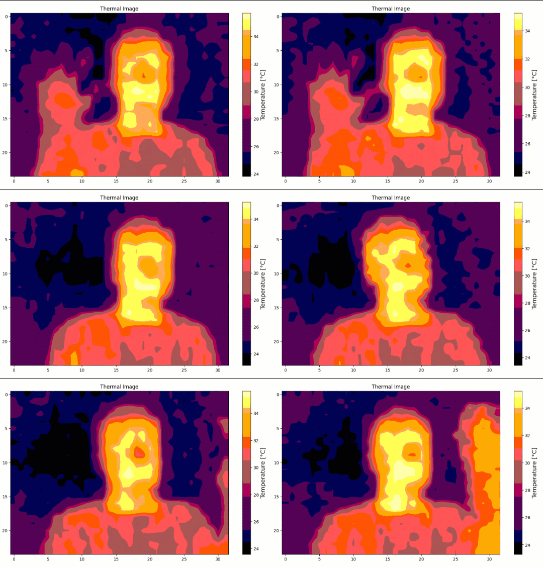
When you run this code, you’ll notice a significant improvement in the visual quality of the thermal video.

The previously pixelated images are now smoother and more visually appealing, showcasing the powerful effect of interpolation.
Video Tutorial & Guide

Conclusion
This project showcases how to build a high-resolution DIY Thermal Imaging Camera using the MLX90640 sensor and a Raspberry Pi. This setup utilizes the MLX90640’s 32×24 array of 768 thermal sensors, significantly surpassing the capabilities of the previously used AMG8833 sensor. It offers enhanced detail with a higher refresh rate of up to 64Hz. By utilizing accessible tools and libraries like Python, Numpy, and Matplotlib, anyone with basic electronics skills can construct a thermal imaging system capable of detecting subtle temperature variations. Whether it’s for practical applications around the home or for capturing unique infrared images, this project provides a valuable, cost-effective introduction to the world of thermal imaging. You can build Fever Detection System using MLX90640 & OpenCV.


6 Comments
Great
Did anyone of you tried running 4 Mlx90640 modules using rasberry pi? I have pi 5b, I have made 4 custom buses in config.txt. Using i2cdetect the cameras are visible but when I try to communicate with them I get messages that no I2c device on the bus. I get the same message if I only try 1 Mlx90640 on one custom bus. During initialization something goes wrong
Olá como você resolveu este erro ?
Traceback (most recent call last):
File “/home/rodrigo/mlx90640_env/visualizacao.py”, line 9, in
mlx = adafruit_mlx90640.MLX90640(i2c)
^^^^^^^^^^^^^^^^^^^^^^^^^^^^^^^
File “/home/rodrigo/.local/lib/python3.11/site-packages/adafruit_mlx90640.py”, line 97, in init
self._ExtractParameters()
File “/home/rodrigo/.local/lib/python3.11/site-packages/adafruit_mlx90640.py”, line 366, in _ExtractParameters
self._ExtractDeviatingPixels()
File “/home/rodrigo/.local/lib/python3.11/site-packages/adafruit_mlx90640.py”, line 760, in _ExtractDeviatingPixels
raise RuntimeError(“More than 4 outlier pixels”)
RuntimeError: More than 4 outlier pixels
(program exited with code: 1)
Press return to continue
Is it possible to use the hdmi output of the raspberry pi instead of a i2c screen?
Yes
This write up is out of date for up-to-date installs of RPi OS such as Trixie. These are the changes I found I needed to make from what is written:-
the /boot/config.txt file is now at /boot/firmware/config.txt
the pip3 install commands fail. You now need to run everything in a Python virtual environment
python3 -m venv myenv
source myenv /bin/activate
then do pip install matplotlib (scipy, numpy etc..)
python-smbus is not in the repository – use python3-smbus2 instead
make sure you also run the visulise scripts within the virtual environment
source myenv /bin/activate
small non-fatal bug on line 16 of the first (without interpolation) script. Add an r like this
cbar.set_label(r’Temperature [$^{\circ}$C]’, fontsize=14)
fatal error in line 28 of the second (with interpolation) script. matplotlib doesn’t use fig.canvas.update( ) – use fig.canvas.draw( ) instead.