

Overview
In this project, we will build Thermal Fever Detector with MLX90640 32X24 Thermal Image Array IR Camera using the OpenCV Python Code on Raspberry Pi System. In previous project, we build a DIY Thermal Imaging Camera using the MLX90640 & Raspberry Pi 4. Later we realized, we could build a fever detection system as well.
The project uses MLX90640 Thermal Camera to detect and visualize thermal hotspots that exceed a specified temperature threshold, suggesting a fever. The Raspberry Pi processes the thermal image data using OpenCV, applies a color map for visualization. Then it continuously monitors and displays the highest temperatures and condition (“Normal” or “Fever Detected“) in a graphical user interface.

During the time of COVID, Thermal Cameras were used for Fever Detection & Identifying possible COVID patient. When Raspberry Pi & OpenCV integrated into a fever detection system, the MLX90640 can scan multiple individuals simultaneously from a safe distance, identifying those with elevated body temperatures that may indicate a fever. This application is particularly useful in public spaces such as airports, hospitals, and schools, where rapid, mass screening is essential for health monitoring and disease prevention.
Bill of Materials
Following are the list of components required to build this OpenCV Python Based Fever Detector. You can purchase all the components from Amazon or the SunFounder.
| S.N. | Components | Quantity | Purchase Link |
|---|---|---|---|
| 1 | Raspberry Pi 4 | 1 | Amazon | SunFounder |
| 2 | MLX90640 Thermal Image Sensor | 1 | Amazon | AliExpress |
| 3 | TS-Pro 7 inch LCD Display | 1 | Amazon | SunFounder |
| 4 | SD Card 16/32 GB | 1 | Amazon | SunFounder |
| 5 | 5V, 3A DC Adapter for RPi | 1 | Amazon | SunFounder |
| 6 | UPS Power Supply with Battery (Optional) | 1 | Amazon | SunFounder |
| 7 | Mouse & Keyboard (Optional) | 1 | Amazon | SunFounder |
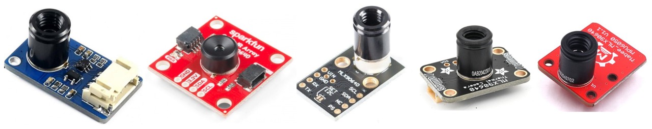
MLX90640 32×24 IR Thermal Imaging Camera

The MLX90640 from Melexis is a small size, non-contact, and low cost far-infrared thermal sensor array that integrates 768 (32×24) thermal sensors into a compact and standard 4-lead TO39 package.
This sensor is capable of capturing detailed thermal images by measuring the infrared radiation emitted by objects in its field of view, translating it into temperature readings ranging from -40°C to 300°C.
The sensor achieves a high degree of accuracy, maintaining approximately ±1°C across its operational range. Furthermore, the MLX90640 includes additional functionalities like an ambient temperature sensor and a supply voltage sensor, enhancing its precision and reliability. Data from the IR sensors, as well as the ambient and supply voltage measurements, are stored in internal RAM and can be accessed via an I2C interface.
The MLX90640 thermal camera features a 32×24 array, totaling 768 individual far-infrared pixels. Each pixel captures temperature data, allowing for detailed thermal imaging and accurate temperature measurements across the sensor’s field of view.
![]()
The MLX90640 is not only functional but also user-friendly, tailored for hobbyists and professionals alike. It supports both 3.3V and 5V operating voltages and communicates through a configurable I2C interface that can reach data rates up to 1MHz. This sensor is compatible with platforms like Arduino, Raspberry Pi, or STM32.
The sensor’s capability to adjust the frame rate from 0.5 to 64Hz allows users to fine-tune its performance based on specific application requirements, whether it’s tracking fast-moving objects or conducting detailed thermal evaluations over a slower period. Refer to MLX90640 Datasheet for more information about this Thermal Camera.
Features and Benefits
- Small size, low cost 32×24 pixels IR array
- Easy to integrate
- Industry standard four lead TO39 package
- Factory calibrated
- Noise Equivalent Temperature Difference (NETD): 0.1K RMS @1Hz refresh rate
- I2C compatible digital interface
- Programmable refresh rate 0.5Hz…64Hz
- 3.3V supply voltage
- Current consumption is less than 23mA
- 2 FOV options – 55°x35° and 110°x75°
- Operating temperature -40°C ÷ 85°C
- Target temperature -40°C ÷ 300°C
- Complies with RoHS regulations
Pinout of MLX90640
The MLX90640 Thermal Camera has 4 pins that need to be connected to the controller and currently supports the Raspberry Pi, STM32F405R, and ESP32 series.
- VCC: Power supply pin, should be connected to the control 3.3V or 5V power supply.
- GND: Ground pin, corresponds to the connection of the ground (GND).
- SDA: Data pin for I2C communication, connected to the GPIO of the controller.
- SCL: Clock pin for I2C communication, connected to the GPIO of the controller
Hardware Setup for Thermal Fever Detector with MLX90640 & Raspberry Pi
Let us interface the MLX90640 Thermal Imaging Camera with Raspberry Pi 4 to build the OpenCV Fever Detector project. The connection is very simple as MLX90640 requires I2C Communication protocol to communicate with Raspberry Pi 4.
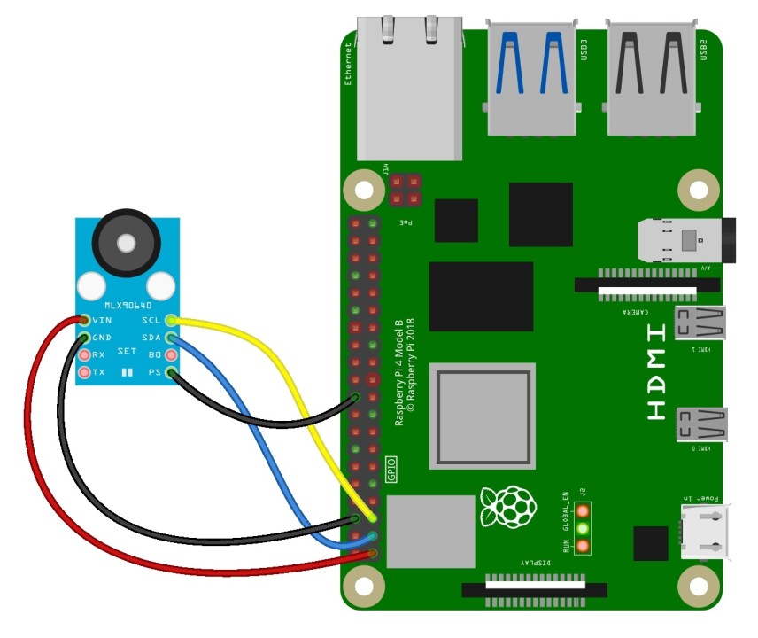
- VCC: Connect the VCC pin of the MLX90640 to one of the 3.3V pins on the Raspberry Pi.
- GND: Connect the GND pin of the MLX90640 to one of the ground pins on the Raspberry Pi.
- SDA: Connect the SDA pin of the MLX90640 to the SDA pin on the Raspberry Pi GPIO (Pin 3).
- SCL: Connect the SCL pin of the MLX90640 to the SCL pin on the Raspberry Pi GPIO (Pin 5).
Note: For one of the module with UART Module Pins, connect PS to GND to enable I2C Communication.
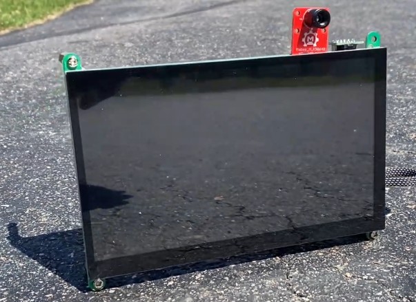
For the visualization of the OpenCV Python Based Thermal Fever Detector , you need a portable HMI Display. In my case, I used a TS-7 Pro 7-inch HMI Display from SounFounder.

With a resolution of 1024×600 pixels, it offers a convenient way to display content and interact with the Raspberry Pi. The Raspberry Pi fits perfectly on the Display.
Similarly, we also need a power supply unit for the Raspberry Pi & the display unit. I used a PiPower UPS Supply from SunFounder, which is a special portable UPS Supply designed for Raspberry Pi 4.

The PCB Board comes along with a 7.4V, 2000mAh Rechargeable Battery.

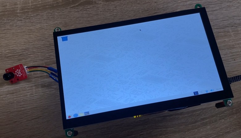
Here is how our device looks after the PiPower Portable UPS Supply is connected to the Raspberry Pi.
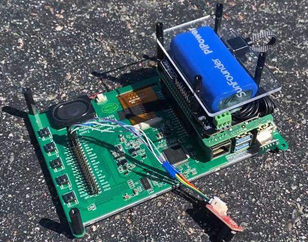
You can slide the Power button on the PiPower PCB and you will see the Raspberry Pi Booting up immediately.
Installing Necessary Libraries & Modules
First, set up your Raspberry Pi by installing the Raspbian operating system. If you have an HDMI monitor, you can begin programming immediately. In my situation, I have linked my Raspberry Pi to the VNC viewer using an SSH terminal, allowing me to program it remotely.
Open your Raspberry Pi Terminal. Let up first start with updating the Raspberry Pi. The following command updates the list of available packages and their versions.
|
1 |
sudo apt-get update |
Then run the upgrade command to install newer versions of the packages you have.
|
1 |
sudo apt-get upgrade |
The following command will install NumPy, a library for large, multi-dimensional arrays and matrices, along with a large collection of mathematical functions to operate on these arrays.
|
1 |
sudo pip3 install numpy |
Then install the python-smbus package, necessary for accessing the I2C bus via Python.
|
1 |
sudo apt-get install -y python-smbus |
The following command will installs i2c-tools, useful for probing and debugging I2C communications.
|
1 |
sudo apt-get install -y i2c-tools |
Now open the Raspberry Pi’s boot configuration file in nano text editor using the following command.
|
1 |
sudo nano /boot/config.txt |

Add dtparam=i2c_arm=on, i2c_arm_baudrate=400000 to enable the I2C interface and set the baud rate for faster data transfer. Save it and go back to terminal
Run the following command now to install Adafruit Blinka library.
|
1 |
sudo pip3 install RPI.GPIO adafruit-blinka |
This install RPi.GPIO for GPIO pin management on the Raspberry Pi and Adafruit Blinka, a compatibility layer to allow CircuitPython libraries to run on Raspberry Pi.
Finally we need to install the Adafruit MLX90640 Library. Therefore run the following command.
|
1 |
sudo pip3 install adafruit-circuitpython-mlx90640 |
Now we need to install the OpenCV Library. To do that run the following sequence of commands.
|
1 2 3 4 5 6 7 8 |
sudo apt-get install libjpeg-dev libtiff5-dev libjasper-dev libpng12-dev sudo apt-get install libavcodec-dev libavformat-dev libswscale-dev libv4l-dev sudo apt-get install libxvidcore-dev libx264-dev sudo apt-get install libgtk2.0-dev sudo apt-get install libatlas-base-dev gfortran sudo apt-get install python3-pip apt list python*opencv* sudo apt install python3-opencv |
Installing OpenCV may take some time, as the libraries are large and require a fast internet connection. To learn more about the installation of OpenCV on Raspberry Pi, you may refer the previous post.
Once all these installation are completed, reboot your Raspberry Pi and the system is ready for developing Fever Detector project with MLX90640 & OpenCV on Raspberry Pi.
Python Code for Thermal Fever Detector using OpenCV
This Python script uses OpenCV and the MLX90640 thermal camera module to detect fever by monitoring temperature patterns via a Raspberry Pi.
It continuously captures thermal images, processes them to normalize and visualize the temperature data, and detects hotspots that exceed a certain threshold, indicating a potential fever. The script also features a GUI for displaying the temperature and condition updates.
|
1 2 3 4 5 6 7 8 9 10 11 12 13 14 15 16 17 18 19 20 21 22 23 24 25 26 27 28 29 30 31 32 33 34 35 36 37 38 39 40 41 42 43 44 45 46 47 48 49 50 51 52 53 54 55 56 57 58 59 60 61 62 63 64 65 66 67 68 69 70 71 72 73 74 |
import cv2 import numpy as np import board import busio import adafruit_mlx90640 # Setup MLX90640 i2c = busio.I2C(board.SCL, board.SDA) mlx = adafruit_mlx90640.MLX90640(i2c) mlx.refresh_rate = adafruit_mlx90640.RefreshRate.REFRESH_2_HZ # Adjust as needed def get_thermal_image(): frame = np.zeros((24*32,)) mlx.getFrame(frame) data_array = np.reshape(frame, (24, 32)) return data_array def process_image(data_array): # Normalize data_array to 0-255 for image processing min_val, max_val = np.min(data_array), np.max(data_array) image = (data_array - min_val) / (max_val - min_val) * 255 image = np.uint8(image) image = cv2.applyColorMap(image, cv2.COLORMAP_JET) # Resize the image to 640x560 to make more space for the GUI image = cv2.resize(image, (640, 560), interpolation=cv2.INTER_CUBIC) return image def detect_hotspots(image, data_array, threshold=36): min_val, max_val = np.min(data_array), np.max(data_array) threshold_value = (threshold - min_val) / (max_val - min_val) * 255 threshold_value = np.uint8(threshold_value) gray = cv2.cvtColor(image, cv2.COLOR_BGR2GRAY) _, thresh = cv2.threshold(gray, threshold_value, 255, cv2.THRESH_BINARY) contours, _ = cv2.findContours(thresh, cv2.RETR_EXTERNAL, cv2.CHAIN_APPROX_SIMPLE) return contours def main(): while True: data_array = get_thermal_image() image = process_image(data_array) condition = "Normal" # Default condition if no hotspots exceed the threshold max_overall_temp = np.max(data_array) # Get the highest temperature for GUI display if max_overall_temp >= 36: condition = "Fever Detected" # Update condition to Fever Detected hotspots = detect_hotspots(image, data_array, threshold=36) for cnt in hotspots: x, y, w, h = cv2.boundingRect(cnt) mask = np.zeros(data_array.shape, dtype=np.uint8) cv2.drawContours(mask, [cnt], -1, 255, thickness=cv2.FILLED) masked_temps = np.where(mask == 255, data_array, np.nan) max_temp = np.nanmax(masked_temps) if np.isnan(max_temp): continue cv2.rectangle(image, (x, y), (x + w, y + h), (0, 255, 0), 2) text_position = (x, max(0, y - 10)) cv2.putText(image, f"{max_temp:.1f}C", text_position, cv2.FONT_HERSHEY_SIMPLEX, 0.9, (255, 255, 255), 2) # GUI Part: Display current max temperature and condition cv2.rectangle(image, (0, 520), (640, 560), (50, 50, 50), -1) cv2.putText(image, condition, (430, 540), cv2.FONT_HERSHEY_SIMPLEX, 0.8, (255, 255, 255), 2) cv2.putText(image, f"Current Max Temp: {max_overall_temp:.1f}C", (10, 540), cv2.FONT_HERSHEY_SIMPLEX, 0.8, (255, 255, 255), 2) cv2.imshow('Thermal Image', image) if cv2.waitKey(1) & 0xFF == ord('q'): break cv2.destroyAllWindows() if __name__ == '__main__': main() |
Fever Detection & Testing
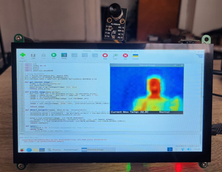
Once all hardware setup and library installation is completed, we can start testing the system. Start the script by executing it in a Thonny on your Raspberry Pi. Ensure the MLX90640 thermal camera is properly connected and configured as the script runs.
The script will open a window displaying the thermal image processed by OpenCV. This image is color-mapped to represent different temperatures visually.
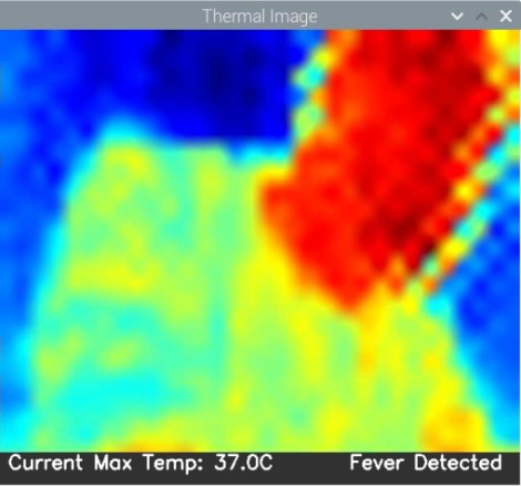
The script identifies areas with temperatures above a specified threshold (36°C) as potential fever hotspots. These areas are highlighted with rectangles in the thermal image.
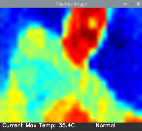
Below the thermal image, the GUI shows a status bar. It displays the highest temperature detected and a condition message:
- If the maximum temperature is below 36°C, it will display “Normal.”
- If the maximum temperature is 36°C or above, it will display “Fever Detected.”
For each detected hotspot, the script calculates the maximum temperature within that region and displays it on the GUI. This helps in assessing whether the detected hotspot is indeed a concern for fever.
Ensure you monitor the GUI while the script is running to see real-time updates and detections. This will allow you to assess whether individuals scanned by the thermal camera potentially have a fever based on their surface temperature readings.
Conclusion
In this project, we built a thermal fever detector using the MLX90640 thermal camera and a Raspberry Pi, enhanced with OpenCV for image processing. This system effectively detects temperature hotspots that exceed predefined thresholds, potentially indicating fever. This technology has proven particularly useful in places like airports and schools where quick health assessments are critical. It’s a great example of how combining simple hardware with powerful software can provide valuable tools for public health monitoring and safety.


