Overview
In this tutorial, we will be interfacing AD8495 Analog Output K-Type Thermocouple Amplifier with ESP32 and displaying the temperature readings on an AJAX-based dynamic web server. Earlier, we used AD8495 with Arduino and Raspberry Pi Pico.
The AD8495 is an analog output thermocouple amplifier. The AD8495 thermocouple amplifiers provide a simple, low-cost solution for measuring thermocouple temperatures. This guide will help you connect the AD8495 K-Type Thermocouple Amplifier with ESP32. Using the datasheet and the mathematical equation for temperature measurement, we will develop code to read the temperature values and display them dynamically on a web server using AJAX for real-time updates.
Bill of Materials
We need the following components for making Digital Thermometer using AD8495 Thermocouple Amplifier & ESP32.
| S.N. | Components Name | Quantity | Purchase Links |
|---|---|---|---|
| 1 | ESP32 Board | 1 | Amazon | AliExpress |
| 2 | AD8495 K-Type Thermocouple Amplifier | 1 | Amazon | AliExpress |
| 3 | Connecting Wires | 5 | Amazon | AliExpress |
| 4 | Breadboard | 1 | Amazon | AliExpress |
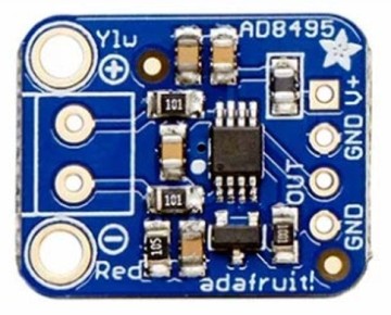
AD8495 K-Type Thermocouple Amplifier
The AD8495 K-Type Thermocouple Amplifier, developed by Analog Devices, is particularly suited for applications requiring high precision. As part of the AD8494/AD8495/AD8496/AD8497 family, it integrates precision instrumentation amplifiers with a cold junction compensator to directly produce a 5 mV/°C output from a K-type thermocouple signal.
This device simplifies the process of temperature measurement by combining an ice point reference with a precalibrated amplifier. This facilitates its use either as a standalone thermometer or as part of a switched output setpoint controller. Specifically calibrated for K-type (chromel-alumel) thermocouples through laser wafer trimming, the AD8495 ensures high accuracy across its optimized ambient temperature range. It supports a wide variety of supply voltages, from 3 V for direct interfacing with low-supply ADCs to up to 36 V for industrial systems requiring broad common-mode input ranges.

The temperature readings can be easily obtained by measuring the output voltage and applying the equation:
For instance, a voltage reading of 1.5VDC translates to a temperature of 50°C. The device’s design minimizes self-heating with a total supply current of 180 μA when unloaded, although it is capable of delivering over ±5 mA to a load. This amplifier comes with a fully assembled PCB, which includes the AD8495 and a TLVH431 1.25V precision voltage reference, a 2-pin terminal block for easy connection to a thermocouple, and a pin header for breadboard integration. Refer to the AD8495 Datasheet for more information.
AD8495 Features & Specifications
- Works with any K-type thermocouple
- Will not work with any other kind of thermocouple other than K type.
- Easy to use analog output.
- Temp range with 5V power: -250°C to +750°C output(0 to 5VDC)
- Temp range with 3.3V power: -250°C to +410°C output(0 to 3.3VDC)
- Sensing Accuracy Range: ± 1°C around room temperature, ± 2°C for −25°C to +400°C
- Sensing Temperature Max: 400°C
- Sensing Temperature Min: -25°C
- Supply Voltage: 3-18V DC
AD8495 Breakout Board Pinout

Power & Output Pins
- V+ – This is the power pin. This board works with 3.3V and 5V power.
- GND – Common ground pins
- OUT – This is the output voltage pin. Read using an analog input.
Thermocouple Terminal
- Red- – Connect the red or – wire on your thermocouple to this side of the screw terminal.
- Ylw+ – Connect the yellow or + wire on your thermocouple to this side of the screw terminal.
Interfacing AD8495 K-Type Thermocouple Amplifier with ESP32
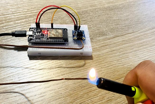
Let us interface the AD8495 K-Type Thermocouple Amplifier with ESP32 WiF-Fi Microcontroller. Here is the connection diagram.
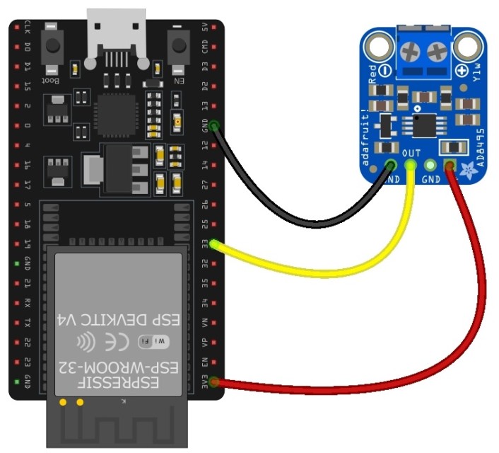
- Connect the VCC of the AD8495 to the 3.3V of ESP32.
- Connect the GND of the AD8495 to a GND pin on the ESP32.
- Finally, connect the Vout (output) of the AD8495 to GPIO33 of ESP32.

You may use a breadboard to place the AD8495 Module. Then, install the thermocouple on the thermocouple terminal of AD8495.
Source Code/Program for Reading Temperature
This code reads a raw ADC value from a thermocouple connected to pin 33 on an ESP32 Then it converts the raw ADC reading to a voltage, and then calculates the temperature from that voltage. The temperature is then printed to the Serial Monitor every 500 milliseconds.
|
1 2 3 4 5 6 7 8 9 10 11 12 13 14 15 16 17 18 19 20 21 22 23 24 25 26 27 28 29 30 31 32 33 34 35 36 37 38 39 40 41 42 43 44 45 46 47 48 49 |
#include "esp_adc_cal.h" #define THERMOCOUPLE_PIN 33 #define ANALOG_REFERENCE_VOLTAGE 3.3 // ESP32 typically uses 3.3V for AREF #define ADC_BIT_RESOLUTION 12 // ESP32 uses 12-bit ADC resolution by default float calculatedVoltage, measuredTemperature; // Function to convert a raw ADC reading to voltage. ESP32's ADC readings can be 12-bit by default, // and we're using 3.3V as the reference voltage. float convertRawAdcToVoltage(uint32_t rawAdcValue) { // Characterize the ADC esp_adc_cal_characteristics_t adcCharacteristics; esp_adc_cal_characterize(ADC_UNIT_1, ADC_ATTEN_DB_11, ADC_WIDTH_BIT_12, 1100, &adcCharacteristics); // Convert the raw ADC value to calibrated voltage in millivolts uint32_t voltageInMilliVolts = esp_adc_cal_raw_to_voltage(rawAdcValue, &adcCharacteristics); // Convert millivolts to volts return voltageInMilliVolts / 1000.0; } float calculateTemperatureFromVoltage(float voltage) { return (voltage - 1.25) / 0.005; } void setup() { Serial.begin(115200); // Note: Additional configuration for the ADC may be necessary depending on your specific setup. } void loop() { // Read the raw ADC value uint32_t rawAdcReading = analogRead(THERMOCOUPLE_PIN); // Convert the raw ADC reading to voltage calculatedVoltage = convertRawAdcToVoltage(rawAdcReading); // Calculate the temperature in Celsius from the voltage measuredTemperature = calculateTemperatureFromVoltage(calculatedVoltage); // Print the measured temperature Serial.print("Temperature = "); Serial.print(measuredTemperature); Serial.println(" °C"); // Delay for a short period before reading the temperature again delay(500); } |
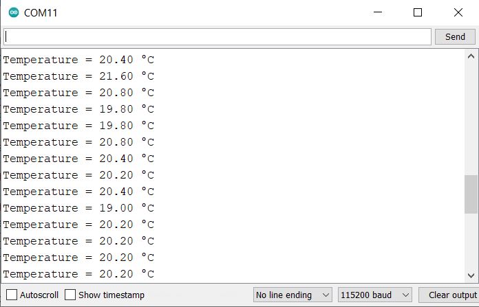
Upload the code to the ESP32 Wi-Fi Module. Once the uploading is done, open the Serial Monitor.
Source Code/Program for ESP32 AD8495 WebServer
The following code connects an ESP32 to a Wi-Fi network, reads the temperature from a thermocouple connected to pin 33, and serves a web page to display the temperature.
It reads the raw ADC value, converts it to voltage, calculates the temperature, and provides a JSON endpoint to get the temperature in both Celsius and Fahrenheit. The temperature data is updated and served to clients via a web server running on the ESP32.
html.h
First save this html file with the name html.h in the folder where main sketch is located.
|
1 2 3 4 5 6 7 8 9 10 11 12 13 14 15 16 17 18 19 20 21 22 23 24 25 26 27 28 29 30 31 32 33 34 35 36 37 38 39 40 41 42 43 44 45 46 47 48 49 50 51 52 53 54 55 56 57 58 59 60 61 62 63 64 65 66 67 68 69 70 71 72 73 74 75 76 77 78 79 80 81 |
const char html_page[] PROGMEM = R"rawString( <!DOCTYPE html> <html lang="en"> <head> <meta charset="UTF-8"> <meta name="viewport" content="width=device-width, initial-scale=1.0"> <title>Temperature Monitor</title> <link href="https://fonts.googleapis.com/css2?family=Roboto:wght@400;500&display=swap" rel="stylesheet"> <style> body { margin: 0; padding: 20px; font-family: 'Roboto', sans-serif; background: #FFFFFF; /* Background color set to white */ color: #333; display: flex; justify-content: center; align-items: center; height: 100vh; overflow: hidden; } .container { text-align: center; padding: 2em; background: rgba(255, 255, 255, 0.95); /* Slightly transparent white for depth */ border-radius: 15px; box-shadow: 0 4px 6px rgba(0, 0, 0, 0.1); /* Soft shadow for a subtle depth effect */ } h1 { color: #333; /* Dark grey text for contrast */ margin-bottom: 1em; } .temperature { display: inline-block; background: rgba(0, 0, 0, 0.05); /* Very light background for the temperature boxes */ color: #333; /* Consistent text color */ padding: 0.5em 1em; border-radius: 8px; margin: 0.5em 0; font-size: 2em; } .temperature span { font-size: 2.5em; font-weight: 500; } .degree-symbol { font-size: 0.5em; vertical-align: super; } @media (max-width: 600px) { .temperature span { font-size: 2em; } } </style> </head> <body> <div class="container"> <h1>ESP32 Temperature Monitor</h1> <div class="temperature"> <span id="TempValueCelsius">--</span><span class="degree-symbol">°C</span> </div> <div class="temperature"> <span id="TempValueFahrenheit">--</span><span class="degree-symbol">°F</span> </div> </div> <script> setInterval(function() { fetch("readTemp") .then(response => response.json()) .then(data => { document.getElementById("TempValueCelsius").innerHTML = data.celsius; document.getElementById("TempValueFahrenheit").innerHTML = data.fahrenheit; }) .catch(error => console.error("Error fetching temperature data:", error)); }, 1000); </script> </body> </html> )rawString"; |
main.ino
Open the new Arduino sketch and save the file in the folder where html.h file is located.
Change the ssid and password and replace with your credentials.
|
1 2 3 4 5 6 7 8 9 10 11 12 13 14 15 16 17 18 19 20 21 22 23 24 25 26 27 28 29 30 31 32 33 34 35 36 37 38 39 40 41 42 43 44 45 46 47 48 49 50 51 52 53 54 55 56 57 58 59 60 61 62 63 64 65 66 67 68 69 70 |
#include <WiFi.h> #include <WebServer.h> #include <esp_adc_cal.h> #include "html.h" // Replace with your network credentials const char* ssid = "***********"; const char* password = "***********"; WebServer server(80); #define THERMOCOUPLE_PIN 33 #define ANALOG_REFERENCE_VOLTAGE 3.3 #define ADC_BIT_RESOLUTION 12 float calculatedVoltage, measuredTemperature; float convertRawAdcToVoltage(uint32_t rawAdcValue) { esp_adc_cal_characteristics_t adcCharacteristics; esp_adc_cal_characterize(ADC_UNIT_1, ADC_ATTEN_DB_11, ADC_WIDTH_BIT_12, 1100, &adcCharacteristics); uint32_t voltageInMilliVolts = esp_adc_cal_raw_to_voltage(rawAdcValue, &adcCharacteristics); return voltageInMilliVolts / 1000.0; } float calculateTemperatureFromVoltage(float voltage) { return (voltage - 1.25) / 0.005; } void setup() { Serial.begin(115200); // Connect to Wi-Fi WiFi.begin(ssid, password); while (WiFi.status() != WL_CONNECTED) { delay(2000); Serial.println("Connecting to WiFi..."); } // Print the IP address Serial.print("IP Address: "); Serial.println(WiFi.localIP()); server.on("/", []() { server.send_P(200, "text/html", html_page); }); server.on("/readTemp", HTTP_GET, []() { float celsius = measuredTemperature; float fahrenheit = celsius * 1.8 + 32; char json[70]; snprintf(json, 70, "{\"celsius\": \"%.2f\", \"fahrenheit\": \"%.2f\"}", celsius, fahrenheit); server.send(200, "application/json", json); }); server.begin(); } void loop() { uint32_t rawAdcReading = analogRead(THERMOCOUPLE_PIN); calculatedVoltage = convertRawAdcToVoltage(rawAdcReading); measuredTemperature = calculateTemperatureFromVoltage(calculatedVoltage); server.handleClient(); } |
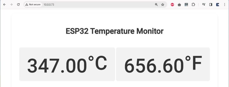
After uploading the code, open the Serial Monitor, the ESP32 local IP address will be displayed. Enter the IP address in the Web browser and hit enter.
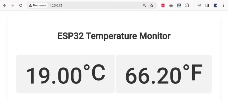
To observe the change in temperature, heat the thermocouple.
You will see rise in temperature.