

Overview
In this tutorial we will be interfacing AD8495 Analog Output K-Type Thermocouple Amplifier with Arduino microcontroller board. Earlier we used MAX6675 Thermocouple Amplifier with Arduino which is an SPI module. The AD8495 is an analog output thermocouple amplifier.
A thermocouple is a rugged, low cost temperature transducer consisting two dissimilar metals. Its output is proportional to the temperature difference between a measurement junction and a reference junction. It has a very wide temperature range. Its low level output (typically tens of microvolts per °C) requires amplification.
The AD8495 thermocouple amplifiers provide a simple, low cost solution for measuring thermocouple temperatures. This hookup guide will help you to connect AD8495 K-Type Thermocouple Amplifier with Arduino UNO Board. Then using the analog output formula, we can write an Arduino code to read the detected temperature. Furthermore, we can add a 0.96″ I2C OLED Display to show the temperature reading on OLED Screen.
Bill of Materials
We need the following components for this tutorial. You can purchase all the components from the given links.
| S.N. | Components | Quantity | Purchase Link |
|---|---|---|---|
| 1 | Arduino UNO Board | 1 | Amazon | AliExpress | SunFounder |
| 2 | AD8495 K-Type Thermocouple Amplifier | 1 | Amazon | AliExpress |
| 3 | 0.96" SSD1306 I2C OLED Display | 1 | Amazon | AliExpress | SunFounder |
| 4 | Jumper Wires | 10 | Amazon | AliExpress | SunFounder |
| 5 | Breadboard | 1 | Amazon | AliExpress | SunFounder |
AD8495 K-Type Thermocouple Amplifier
The AD8495 K-Type Thermocouple Amplifier, developed by Analog Devices, is particularly suited for applications requiring high precision. As part of the AD8494/AD8495/AD8496/AD8497 family, it integrates precision instrumentation amplifiers with a cold junction compensator to directly produce a 5 mV/°C output from a K-type thermocouple signal.
This device simplifies the process of temperature measurement by combining an ice point reference with a precalibrated amplifier. This facilitates its use either as a standalone thermometer or as part of a switched output setpoint controller. Specifically calibrated for K-type (chromel-alumel) thermocouples through laser wafer trimming, the AD8495 ensures high accuracy across its optimized ambient temperature range. It supports a wide variety of supply voltages, from 3 V for direct interfacing with low-supply ADCs to up to 36 V for industrial systems requiring broad common-mode input ranges.

The temperature readings can be easily obtained by measuring the output voltage and applying the equation:
For instance, a voltage reading of 1.5VDC translates to a temperature of 50°C. The device’s design minimizes self-heating with a total supply current of 180 μA when unloaded, although it is capable of delivering over ±5 mA to a load. This amplifier comes with a fully assembled PCB, which includes the AD8495 and a TLVH431 1.25V precision voltage reference, a 2-pin terminal block for easy connection to a thermocouple, and a pin header for breadboard integration. Refer to the AD8495 Datasheet for more information.
AD8495 Features & Specifications
- Works with any K-type thermocouple
- Will not work with any other kind of thermocouple other than K type.
- Easy to use analog output.
- Temp range with 5V power: -250°C to +750°C output(0 to 5VDC)
- Temp range with 3.3V power: -250°C to +410°C output(0 to 3.3VDC)
- Sensing Accuracy Range: ± 1°C around room temperature, ± 2°C for −25°C to +400°C
- Sensing Temperature Max: 400°C
- Sensing Temperature Min: -25°C
- Supply Voltage: 3-18V DC
AD8495 Block Diagram & Internal Circuitry
The following image shows a block diagram of the AD8495 circuitry. The AD849x consists of a low offset, fixed-gain instrumentation amplifier, and a temperature sensor.
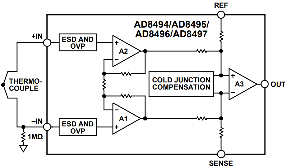
The AD849x output is a voltage that is proportional to the temperature at the measurement junction of the thermocouple (TMJ). A thermocouple signal is so small that considerable gain is required before it can be sampled properly by most ADCs. The AD849x has an instrumentation amplifier with a fixed gain that generates an output voltage of 5 mV/°C for J-type and K-type thermocouples.
The AD8495 also includes a temperature sensor for cold junction compensation. This temperature sensor is used to measure the reference junction temperature of the thermocouple and to cancel its effect. An ideal AD8495 achieves this output with an error of less than ±2°C.
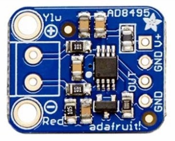
Adafruit AD4895 Breakout Board Schematic

AD8495 Breakout Board Pinout

Power & Output Pins
- V+ – This is the power pin. This board works with 3.3V and 5V power.
- GND – Common ground pins
- OUT – This is the output voltage pin. Read using an analog input.
Thermocouple Terminal
- Red- – Connect the red or – wire on your thermocouple to this side of the screw terminal.
- Ylw+ – Connect the yellow or + wire on your thermocouple to this side of the screw terminal.
Interfacing AD8495 Analog K-Type Thermocouple Amplifier with Arduino
Now let us interface the AD8495 Analog K-Type Thermocouple Amplifier with Arduino. The connection is fairly simple.

- Connect the VCC of the AD8495 to the 5V on the Arduino.
- Connect the GND of the AD8495 to a GND pin on the Arduino.
- Finally, connect the Vout (output) of the AD8495 to one of the Arduino’s analog input pins (e.g., A0)
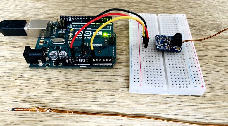
You may use a breadboard to fit the AD8495 Module. Properly install the thermocouple on the thermocouple terminal of AD8495.
Source Code/Program for Reading the Temperature Value
Here is an Arduino code for interfacing AD8495 Analog Output K-Type Thermocouple Amplifier with Arduino.
This code performs the following actions:
- Reads a temperature value from a thermocouple connected to an Arduino’s analog input pin, converting the raw analog-to-digital converter (ADC) value to a voltage.
- Calculates the temperature in Celsius from the voltage using the characteristics of an AD8495 thermocouple amplifier (5mV per degree Celsius with a 1.25V offset at 0°C).
- Outputs the measured temperature to the Serial Monitor every 500 milliseconds.
|
1 2 3 4 5 6 7 8 9 10 11 12 13 14 15 16 17 18 19 20 21 22 23 24 25 26 27 28 29 30 31 32 33 34 35 36 37 38 39 40 41 42 43 44 45 46 47 48 49 50 51 52 53 54 |
// Define the ADC pin to which the thermocouple output is connected. #define THERMOCOUPLE_PIN A0 // Define the analog reference voltage (AREF). This should match your board's voltage, typically 3.3V or 5.0V. #define ANALOG_REFERENCE_VOLTAGE 5.0 // Define the ADC resolution in bits. For many Arduino models, the default resolution is 10 bits. #define ADC_BIT_RESOLUTION 10 // Variables to store the raw ADC reading, the calculated voltage, and the calculated temperature. float rawAdcReading, calculatedVoltage, measuredTemperature; // Function to convert a raw ADC reading to voltage. // The function takes the raw ADC value as an input and returns the corresponding voltage. float convertRawAdcToVoltage(int rawAdcValue) { // The ADC value is converted to voltage by multiplying with the voltage step size. // The step size is determined by the analog reference voltage and the ADC resolution. return rawAdcValue * (ANALOG_REFERENCE_VOLTAGE / (pow(2, ADC_BIT_RESOLUTION) - 1)); } // Function to calculate the temperature in Celsius from the thermocouple voltage. // The function takes the measured voltage as input and returns the temperature in Celsius. float calculateTemperatureFromVoltage(float voltage) { // The AD8495 outputs 5mV per degree Celsius with a 1.25V offset at 0°C. // To find the temperature, subtract the offset and divide by the voltage per degree Celsius. return (voltage - 1.25) / 0.005; } void setup() { // Initialize serial communication at 9600 bits per second. Serial.begin(9600); } void loop() { // Read the raw ADC value from the thermocouple pin. rawAdcReading = analogRead(THERMOCOUPLE_PIN); // Convert the raw ADC reading to voltage. calculatedVoltage = convertRawAdcToVoltage(rawAdcReading); // Calculate the temperature in Celsius from the voltage. measuredTemperature = calculateTemperatureFromVoltage(calculatedVoltage); // Print the measured temperature to the Serial Monitor. Serial.print("Temperature = "); Serial.print(measuredTemperature); Serial.println(" °C"); // Wait for 500 milliseconds before the next reading. delay(500); } |
Upload the code to the Arduino Board and open the Serial Monitor.

The Serial Monitor will display the latest temperature reading of your room.
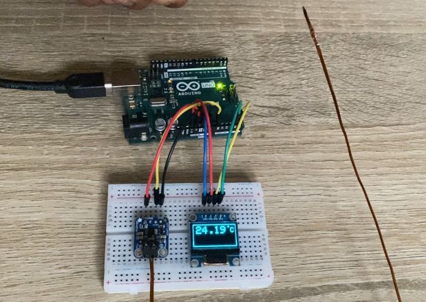
Displaying the Temperature Reading on OLED Display
Let us add an extra OLED Display to the above circuit to display the thermocouple temperature reading. The OLED Display is based on SSD1306 I2C OLED driver. The connection between OLED Display & Arduino is very simple.

- Connect the VCC of the OLED to the 3.3V on the Arduino.
- Connect the GND of the OLED to a GND pin on the Arduino.
- Then, Connect the SDA of the OLED to the A4 on the Arduino.
- Finally, Connect the SCL of the OLED to a A5 pin on the Arduino.

Insert the OLED Display on the breadboard & use the jumper wires to connect it to the Arduino Board.
The following code will display the temperature readings on OLED Display. The code requires Adafruit SSD1306 and Adafruit GFX library. Add these two libraries to the Arduino Library Folder & upload the following code to your Arduino Board.
|
1 2 3 4 5 6 7 8 9 10 11 12 13 14 15 16 17 18 19 20 21 22 23 24 25 26 27 28 29 30 31 32 33 34 35 36 37 38 39 40 41 42 43 44 45 46 47 48 49 50 51 52 53 54 55 56 57 58 59 60 61 62 63 64 65 66 67 68 69 70 71 72 73 74 75 76 77 78 79 80 81 82 83 84 85 86 87 88 89 90 91 92 93 94 95 96 |
#include <Wire.h> #include <Adafruit_GFX.h> #include <Adafruit_SSD1306.h> #define THERMOCOUPLE_PIN A0 #define ANALOG_REFERENCE_VOLTAGE 5.0 #define ADC_BIT_RESOLUTION 10 #define SCREEN_WIDTH 128 // OLED display width, in pixels #define SCREEN_HEIGHT 64 // OLED display height, in pixels #define OLED_RESET -1 //Reset pin # (or -1 if sharing Arduino reset pin) #define SCREEN_ADDRESS 0x3C //See datasheet for Address Adafruit_SSD1306 display(SCREEN_WIDTH, SCREEN_HEIGHT, &Wire, OLED_RESET); float rawAdcReading, calculatedVoltage, measuredTemperature; float convertRawAdcToVoltage(int rawAdcValue) { return rawAdcValue * (ANALOG_REFERENCE_VOLTAGE / (pow(2, ADC_BIT_RESOLUTION) - 1)); } float calculateTemperatureFromVoltage(float voltage) { return (voltage - 1.25) / 0.005; } void setup() { Serial.begin(9600); // SSD1306_SWITCHCAPVCC = generate display voltage from 3.3V internally if (!display.begin(SSD1306_SWITCHCAPVCC, SCREEN_ADDRESS)) { Serial.println(F("SSD1306 allocation failed")); for (;;); // Don't proceed, loop forever } display.clearDisplay(); display.display(); delay(500); } void loop() { dispTemp(); display.clearDisplay(); } void dispTemp(void) { rawAdcReading = analogRead(THERMOCOUPLE_PIN); calculatedVoltage = convertRawAdcToVoltage(rawAdcReading); measuredTemperature = calculateTemperatureFromVoltage(calculatedVoltage); Serial.print("Temperature = "); Serial.print(measuredTemperature); Serial.println(" °C"); displaytemp(measuredTemperature, 'C'); // call to function void displaytemp(float temp, char C_F) giving temperature in Deg C and character C delay(500); // wait for 500ms and then clear display, you can adjust this time to increase or decrease duration of displaying Deg C or Deg F display.clearDisplay(); } void displaytemp(float temp, char C_F) // function to display temp, takes temperature and character C or F from calling function void dispTemp(void) { display.drawRect(1, 1, display.width() - 1, display.height() - 1, WHITE); // draws the outer rectangular boundary on the screen display.setTextColor(WHITE); // i have white OLED display, you can use other colors in case you have multicolored display display.setTextSize(1); // i have used large font to display temperature, it can be varied as per your taste display.setCursor(104, 3); display.print("o"); // this prints the "o" symbol to show Degree display.setTextSize(2); display.setCursor(112, 10); display.print(C_F); // this takes character from function call either C or F for centigrade of farenheit if (temp >= 100 || temp < 0) { //i have reduced font size if temp goes in 3 digits or is -ve, keeps text in center of display , it can be varied as per your taste display.setTextSize(2); display.setCursor(15, 10); } else if (temp < 10 && temp >= 0) { //some adjustments to keep text in center of display , it can be varied as per your taste display.setTextSize(3); display.setCursor(25, 6); } else { display.setTextSize(3); //i have used large font to display temperature, it can be varied as per your taste display.setCursor(10, 6); } display.print(temp); // finally prints the temperature on your OLED display display.display(); } |
Testing High Temperature for AD8495 Thermocouple Amplifier
After uploading the above code, the OLED Display will start showing the temperature of your room.
You may heat the Thermocouple with any heating source and you will observer the quickly rise in temperature.
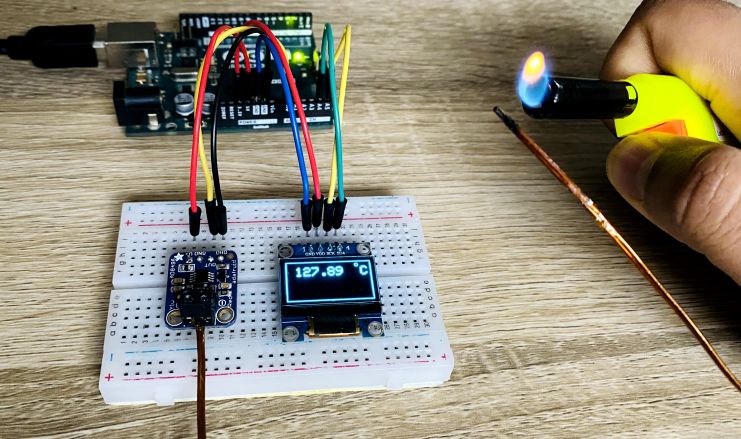
Heating the Thermocouple will give further give rise in temperature.

You may heat the thermocouple for long period of time to observer the rise in temperature reading.

The maximum temperature the AD8495 Analog Output K-Type Thermocouple Amplifier measure is +750°C. For measuring low temperatures you may put the thermocouple in the ice or liquid nitrogen. The lowest temperature it can measure is upto -250°C.

")


