

Overview
In this project, we will build an IoT-based Smart Electricity Energy Meter using ESP32 and the newly updated Blynk 2.0 application. We have previously built an IoT DC Energy Meter, GSM Prepaid Energy Meter and also an IoT Energy Meter using ESP32 using the old Blynk Application, but with the recent upgrade of the Blynk platform, it was necessary to upgrade our Energy Meter project as well. Our aim is to automate the process of monitoring electricity consumption and make it a more streamlined experience.
Traditionally, monitoring electricity consumption involves manual meter readings, which can be time-consuming and inconvenient. The Internet of Things provides a solution by automating remote data collection, thereby saving time and money. The concept of a Smart Energy Meter has gained significant popularity worldwide in recent years, making this an excellent opportunity to build our own IoT-based electricity energy meter.
We will create an IoT-based Smart Electricity Energy Meter using ESP32 and the updated Blynk 2.0 application. By using the best current sensor (SCT-013) and voltage sensor (ZMPT101B), we can measure voltage, current, power, and total energy consumed in kWh. The readings will be sent to the Blynk 2.0 application and displayed on a dashboard accessible from any location. In case of power outages, the energy meter data will be stored in ESP32’s EEPROM, ensuring continuous readings. Let’s start our project to automate electricity consumption monitoring.
Bill of Materials
Below, is the list of components necessary for constructing an IoT-based Smart Electricity Energy meter. You can order most of these components online from the following links.
| S.N. | Components | Quantity | |
|---|---|---|---|
| 1 | ESP32 WiFi Module | 1 | Amazon | AliExpress |
| 2 | ZMPT101B AC Voltage Sensor Module | 1 | Amazon | AliExpress |
| 3 | SCT-013-030 Non-invasive AC Current Sensor | 1 | Amazon | AliExpress |
| 4 | 20x4 I2C LCD Display | 1 | Amazon | AliExpress |
| 5 | Micro-USB Cable | 1 | Amazon | AliExpress |
| 6 | Resistor 10K | 2 | Amazon | AliExpress |
| 7 | Resistor 100ohm | 1 | Amazon | AliExpress |
| 8 | Capacitor 10uF | 1 | Amazon | AliExpress |
| 9 | Connecting Wires | 10 | Amazon | AliExpress |
| 10 | Breadboard | 1 | Amazon | AliExpress |
SCT-013 Current Sensor
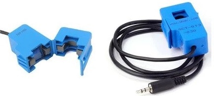
The SCT-013 is a non-invasive split-core type clamp meter sensor designed to measure AC current up to 100 amperes. This type of current sensor is commonly known as a current transformer (CT) and is used for measuring alternating current in a building. The SCT-013 is convenient to use, as it can be easily attached to either the live or neutral wire without any electrical work involving high voltage.
![]()
The sensor has a primary winding, magnetic core, and secondary winding, which is composed of many turns of fine wire enclosed in the transformer casing.
Specifications
1. Input Current: 0-30A AC
2. Output Signal: DC 0-1 V
3. Non-linearity: 2-3 %
4. Build-in sampling resistance (RL): 62 Ω
5. Turn Ratio: 1800:1
6. Resistance Grade: Grade B
7. Work Temperature: -25 °C~+70 °C
8. Dielectric Strength (between shell and output): 1000 V AC / 1 min 5 mA
ZMPT101B AC Single Phase Voltage Sensor

The ZMPT101B AC Single Phase Voltage Sensor Module is a high-precision device built on the ZMPT101B voltage transformer. This makes it an ideal choice for measuring accurate AC voltage with an Arduino or ESP32.
The module is capable of measuring AC voltage within a range of 250V and offers adjustable analog output. It is easy to use, featuring a multi-turn trim potentiometer for adjusting and calibrating the ADC output.
Specifications
1. Voltage up to 250 volts can be measured
2. Lightweight with on-board micro-precision voltage transformer
3. High precision on-board op-amp circuit
4. Operating temperature : 40ºC ~ + 70ºC
5. Supply voltage 5 volts to 30 volts
You can use ZMPT101B for AC Voltage Monitoring applications.
Circuit Diagram & Hardware Setup
The circuit diagram for the IoT-based Electricity Energy Meter using ESP32 is shown below. The design was created using the Fritzing software and the connection diagram is simple.

The VCC & GND pins of both the SCT-013 Current Sensor and ZMPT101B Voltage Sensor are connected to the Vin & GND of ESP32, which is a 5V supply. The output analog pin of the ZMPT101B Voltage Sensor is connected to the GPIO35 of ESP32 and the output analog pin of the SCT-013 Current Sensor is connected to the GPIO34 of ESP32. Additionally, two 10K resistors and a single 100-ohm resistor, along with a 10uF capacitor, are required to complete the circuit.

To measure the current and voltage, the AC wires must be connected to the input AC Terminal of the Voltage Sensor. For the Current Sensor, only a single live or neutral wire needs to be inserted inside the clip part.

An optional 20×4 I2C LCD display can also be used, but it requires additional connections. Connect the VCC, GND, SDA & SCL of the LCD Display to ESP32 5V, GND, GPIO21 & GPIO 22 of ESP32 respectively. A 10K Potentiometer at the back of the I2C Module is used to adjust the LCD contrast. Alternatively, the ESP32/SCT-013/ZMPT101B Energy Meter data can be monitored on the Blynk Application without connecting the LCD display.
Setting Up Blynk 2.0 Web and Mobile Dashboard
Blynk is an application that runs over Android and IOS devices to control any IoT based application using Smartphones. It allows you to create your Graphical user interface for IoT application. Here we will display the IoT Energy Meter Data on Blynk Web Dashboard and also in mobile Application.
Visit blynk.io and sign up using the email ID.
First Create a New Template.

Assign the name, Hardware & Connection Type.

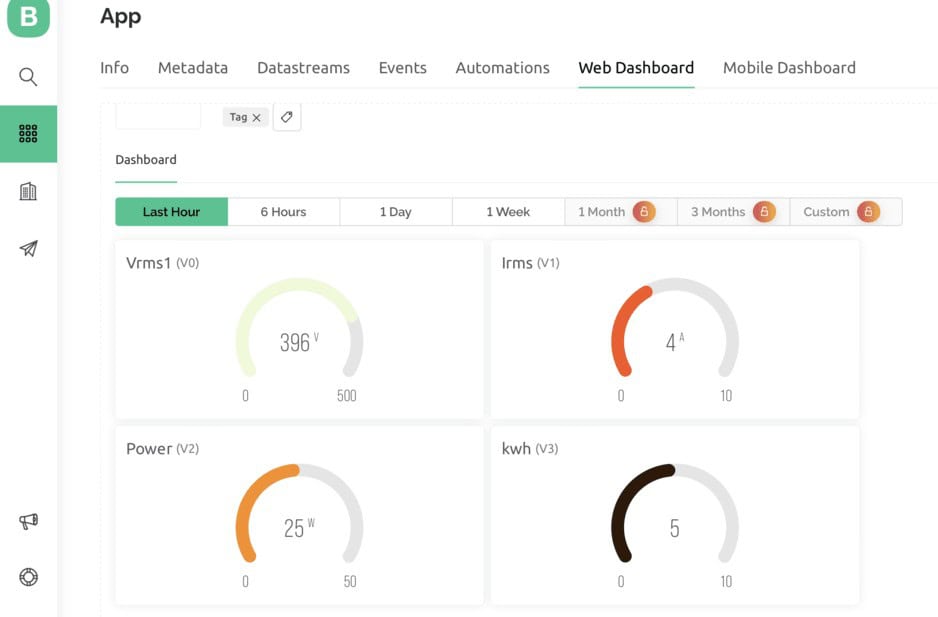
From the Web Dashboard, Create 4 widgets Gauge.

The 4 widgets are here to display the value of Vrms, Irms, Power & KWh. Do the settings as per the image below.


Finally the Web Dashboard looks something like this and is ready to receive the Smart Energy Meter Data from ESP32.

Apart from the Web Dashboard, you can also set up your Mobile App Dashboard.
You can download and install the Blynk Application from Google Play Store. IOS users can download from the App Store.
Once the installation is completed, open the app & sign-up using your Email id and Password. Then set up the app similar like Web Dashboard.

Required Library Installation
1. EmonLib Library
The Emonlib Library is used for Electricity Energy Meter. EmonLib is a Continuous Monitoring of Electricity Energy repeats, every 5 or 10s, a sequence of voltage and current measurements. EemonLib continuously measures in the background the voltage and all the current input channels, calculates a true average quantity for each, and then informs the sketch that the measurements are available and should be read and processed.
2. Blynk Library
Blynk is the most popular Internet of Things platform for connecting any hardware to the cloud, designing apps to control them, and managing your deployed products at scale. With Blynk Library you can connect over 400 hardware models including Arduino, ESP8266 & ESP32 to the Blynk Cloud.
ZMPT101B Voltage Sensor Calibration
Initially the ZMPT101B Voltage Sensor requires calibration as it doesn’t come pre-calibrated. To calibrate the sensor, we can use an Arduino UNO/Nano Board. Since Arduino UNO/Nano has a perfect linear ADC pin, it can be a good choice for calibration. You can use analog pin A0 of Arduino to calibrate the sensor.
Now upload the following code to the Arduino Board.
|
1 2 3 4 5 6 7 8 9 10 |
void setup() { Serial.begin(9600); } void loop() { Serial.println(analogRead(A0)); delay(100); } |
After uploading the code, open the Serial Plotter. If the Serial Plotter doesn’t show the sine wave, then rotate the potentiometer to calibrate the sensor. Once it shows a proper sine wave, you can assume it is a proper calibration.

Source Code/Program for IoT Smart Energy Meter
This code is an Arduino sketch that implements an IoT energy meter using an ESP32 board. The code uses several libraries such as LiquidCrystal_I2C, EmonLib, EEPROM, WiFi, WiFiClient, and BlynkSimpleEsp32.
Copy this code below and paste it on your Arduino IDE.
In this code make changes to following lines. These lines has WiFi SSID, Password and Blynk Authentication Token. Replace them with your credentials.
|
1 2 3 4 |
// Blynk and WiFi credentials const char auth[] = "********************************"; const char ssid[] = "********************************"; const char pass[] = "********************************"; |
Now after making the modifications in the required line, you may upload the code to your ESP32 Board. For that Select the ESP32 Dev Module and the COM Port. Then Hit the upload button to upload the code.
|
1 2 3 4 5 6 7 8 9 10 11 12 13 14 15 16 17 18 19 20 21 22 23 24 25 26 27 28 29 30 31 32 33 34 35 36 37 38 39 40 41 42 43 44 45 46 47 48 49 50 51 52 53 54 55 56 57 58 59 60 61 62 63 64 65 66 67 68 69 70 71 72 73 74 75 76 77 78 79 80 81 82 83 84 85 86 87 88 89 90 91 92 93 94 95 96 97 98 99 100 101 102 103 104 105 106 107 108 109 110 111 112 113 114 115 116 117 118 119 120 121 122 123 124 125 126 127 128 129 130 131 132 133 134 135 136 137 138 139 140 141 142 143 144 145 146 |
#define BLYNK_TEMPLATE_ID "********************************" #define BLYNK_TEMPLATE_NAME "IoT Energy Meter" #define BLYNK_PRINT Serial #include "EmonLib.h" #include <EEPROM.h> #include <WiFi.h> #include <WiFiClient.h> #include <BlynkSimpleEsp32.h> #include <Wire.h> #include <LiquidCrystal_I2C.h> LiquidCrystal_I2C lcd(0x27, 20, 4); // Constants for calibration const float vCalibration = 41.5; const float currCalibration = 0.15; // Blynk and WiFi credentials const char auth[] = "********************************"; const char ssid[] = "********************************"; const char pass[] = "********************************"; // EnergyMonitor instance EnergyMonitor emon; // Timer for regular updates BlynkTimer timer; // Variables for energy calculation float kWh = 0.0; unsigned long lastMillis = millis(); // EEPROM addresses for each variable const int addrVrms = 0; const int addrIrms = 4; const int addrPower = 8; const int addrKWh = 12; // Function prototypes void sendEnergyDataToBlynk(); void readEnergyDataFromEEPROM(); void saveEnergyDataToEEPROM(); void setup() { Serial.begin(115200); Blynk.begin(auth, ssid, pass); // Initialize the LCD lcd.init(); lcd.backlight(); // Initialize EEPROM with the size of the data to be stored EEPROM.begin(32); // Allocate 32 bytes for float values (4 bytes each) and some extra space // Read the stored energy data from EEPROM readEnergyDataFromEEPROM(); // Setup voltage and current inputs emon.voltage(35, vCalibration, 1.7); // Voltage: input pin, calibration, phase_shift emon.current(34, currCalibration); // Current: input pin, calibration // Setup a timer for sending data every 5 seconds timer.setInterval(5000L, sendEnergyDataToBlynk); // A small delay for system to stabilize delay(1000); } void loop() { Blynk.run(); timer.run(); } void sendEnergyDataToBlynk() { emon.calcVI(20, 2000); // Calculate all. No.of half wavelengths (crossings), time-out // Calculate energy consumed in kWh unsigned long currentMillis = millis(); kWh += emon.apparentPower * (currentMillis - lastMillis) / 3600000000.0; lastMillis = currentMillis; // Print data to Serial for debugging Serial.printf("Vrms: %.2fV\tIrms: %.4fA\tPower: %.4fW\tkWh: %.5fkWh\n", emon.Vrms, emon.Irms, emon.apparentPower, kWh); // Save the latest values to EEPROM saveEnergyDataToEEPROM(); // Send data to Blynk Blynk.virtualWrite(V0, emon.Vrms); Blynk.virtualWrite(V1, emon.Irms); Blynk.virtualWrite(V2, emon.apparentPower); Blynk.virtualWrite(V3, kWh); // Update the LCD with the new values lcd.clear(); lcd.setCursor(0, 0); lcd.print("Vrms: "); lcd.print(emon.Vrms, 2); lcd.print(" V"); lcd.setCursor(0, 1); lcd.print("Irms: "); lcd.print(emon.Irms, 4); lcd.print(" A"); lcd.setCursor(0, 2); lcd.print("Power: "); lcd.print(emon.apparentPower, 4); lcd.print(" W"); lcd.setCursor(0, 3); lcd.print("kWh: "); lcd.print(kWh, 5); lcd.print(" kWh"); } void readEnergyDataFromEEPROM() { // Read the stored kWh value from EEPROM EEPROM.get(addrKWh, kWh); // Check if the read value is a valid float. If not, initialize it to zero if (isnan(kWh)) { kWh = 0.0; saveEnergyDataToEEPROM(); // Save initialized value to EEPROM } } void saveEnergyDataToEEPROM() { // Write the current kWh value to EEPROM EEPROM.put(addrKWh, kWh); // Commit changes to EEPROM EEPROM.commit(); } |
Testing ESP32 IoT Energy Meter Data on Blynk 2.0
The ESP32 Board will try connecting to the wifi Network using the given SSID & Password. The LCD Display will light up with the following message Initially.

When no load is connected or when the load is powered off the Current and Voltage parameters should be almost 0. If it shows some other value, then you need to modify the following calibration factor in the code.
|
1 2 |
#define vCalibration 41.5 #define currCalibration 0.15 |

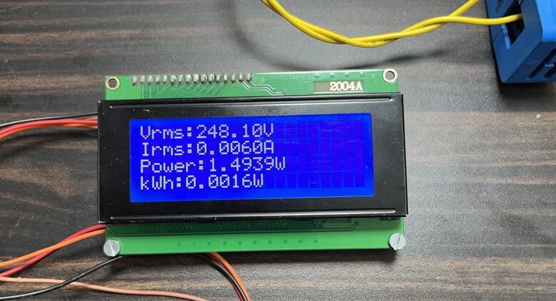
Now when the load is connected, the LCD Display will display the Voltage and Current value on LCD Screen along with Power Consumption and total kWh units.
The energy meter data is uploaded to Blynk Application after the interval of every 5 seconds. The data can be observed on Blynk Web Dashboard.
Similarly you can also observe the data on Mobile Web Dashboard at the same time.
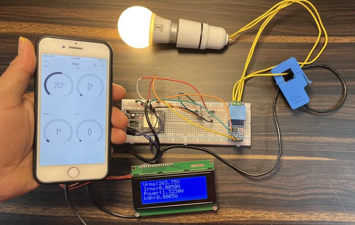
Thus, you can use this ESP32 IoT Energy Meter with Blynk 2.0 to monitor the electricity consumption of your house.
Video Tutorial & Guide

Conclusion
In conclusion, the development of a IoT Based Smart Electricity Energy Meter using ESP32 and Blynk 2.0 will bring about a revolution in the monitoring and measurement of electricity consumption. The IoT-based solution eliminates manual meter readings, saving time and money.
With the use of the best current and voltage sensors, accurate readings of voltage, current, power, and total energy consumed can be obtained. The power can be calculated using the AC Wattage Calculator. The data can be accessed from any location through the Blynk 2.0 dashboard. In case of power outages, the energy meter data is stored in ESP32’s EEPROM, ensuring continuous readings.
This project presents an opportunity to automate electricity consumption monitoring and make it a more streamlined experience.
There is a better version of energy meter project based on HDMI Display. Please check: IoT AC Energy Meter with HDMI Display, where data can also be monitored on HDMI Display.
Incase, you want more accurate results then you can use PZEM-004T AC Energy Meter module which can be interfaced with Arduino and ESP32 Microcontroller.
 & Live Dashboard")


14 Comments
This is the project I’ve been waiting for. ♥️🥺
is good
Hello.
I want to be able to measure the consumption of energy but is it possible using Lcd only and not the softwares
#define vCalibration 83.3
#define currCalibration 0.5
#define vCalibration 106.8
#define currCalibration 0.52
You had given these values when making with sct 013 030 current sensor. what value should i write if using acs712t elc-20a current sensor
how do you know value of vcalibration & currcalibration
PLEASE TELL , WHICH SOFTWARE TO USE DRAW THE CIRCUIT DIAGRAM
Did you find out
WHAT SHOULD BE THE AD ON CODE TO DISPLAY POWER FACTOR.
I WANT TO MAKE A SIMILAR PROJECT BUT NON IOT BASED
error compiling for board doit esp32 devkit v1
Can anyone help me make this project using ACS 712. I am having hard time
Hey did you figure it out
Hai Admin , i used nodemcu esp32s in this circuit , voltage and current calibration value is very low , how to fix my problem.
can you share the Gerber file for the 2.0 version.
Does this project will measure cos(phi) i.e. power factor here in this project no ZCD (Zero Crossing Detector) mentioned. Please reply.