

Overview
In this tutorial, we’ll explore the Modbus RTU protocol and learn how to implement it with a Raspberry Pi Pico using MicroPython to read sensor data from a slave device via RS485. We’ll use a humidity and temperature sensor operating under the Modbus RTU protocol to simplify our learning process. The Raspberry Pi Pico will be programmed to communicate and retrieve sensor data using RS-485, offering a practical insight into this communication technique.
Modbus is a communication protocol that was developed in 1979 primarily for use with programmable logic controllers (PLCs). Since then, it has become a standard protocol extensively used in the industrial sector for connecting various industrial electronic devices.
Modbus RTU (Remote Terminal Unit) is a variant of the Modbus protocol that uses binary coding and serial communication to facilitate quick data transmission. It is commonly used in industrial environments to connect sensors, instruments, and actuaries to controllers and computers, mainly via RS-485 serial interfaces. This is especially beneficial for applications that demand reliable data exchange across long distances or in areas with significant electrical interference.
Components Required
To learn, how to implement Modbus RTU protocol with Raspberry Pi Pico, we need the following components.
| S.N. | Components Name | Quantity | Purchase Link |
|---|---|---|---|
| 1 | Raspberry Pi Pico | 1 | Amazon | AliExpress |
| 2 | MAX485 Modbus Module | 1 | Amazon | AliExpress |
| 3 | RS485 Temperature Humidity Sensor | 1 | AliExpress |
| 4 | Connecting Wires | 10 | Amazon | AliExpress |
| 5 | Breadboard | 2 | Amazon | AliExpress |
What is Modbus?
Modbus is a serial communication protocol developed by Modicon in 1979, initially designed for Modicon programmable logic controllers (PLCs) for industrial applications. Over time, it has become a standard protocol used widely across various automation products to connect industrial electronic devices. Modbus is particularly useful for monitoring and communicating between intelligent devices, sensors, or instruments, and for managing field devices using computers and Human Machine Interfaces (HMIs). It is also well-suited for Remote Terminal Unit (RTU) applications that require wireless communication, making it ideal for gas and oil substation applications due to its openness, simplicity, low-cost development, and minimal hardware requirements.

In a typical Modbus network, there is one master device and up to 247 slave devices, each with a unique address. The master device orchestrates the data management and writes data to the slaves. Data transfer in Modbus is in the form of binary bits—zeroes and ones—which represent positive and negative voltages respectively. These bits are transmitted rapidly between devices due to their small size.
There are three main variations of the Modbus protocol:
- Modbus ASCII
- Modbus RTU
- Modbus TCP/IP
These variations accommodate different types of networks and data transmission requirements.
What is Modbus RTU?
Modbus RTU (Remote Terminal Unit) is a widely utilized serial communication protocol in building management and industrial automation systems.
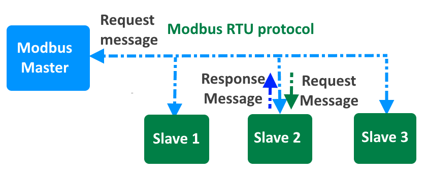
It facilitates the connection and communication between various devices, such as controllers, sensors, and actuators, often in environments where the devices may be spread over distances up to 15 meters. This protocol operates on a point-to-point basis, featuring a single master device that communicates with one or more slave devices in a network.
Technically, Modbus RTU employs binary data encoding for efficient data transmission and includes CRC (Cyclic Redundancy Check) error checking to ensure the integrity of data during transmission. This robust error-checking mechanism helps prevent data corruption across the physical network.
Modbus RTU is strictly confined to its specific communication standards, meaning devices configured for different modes (e.g., ASCII versus RTU) cannot interact. For instance, a device set up for ASCII communication will not be able to interpret data from a device sending data in RTU binary format.

The physical layer of Modbus RTU typically uses one of three types of electrical interfaces:
- RS-232: Suitable for short-distance communications and often used for connections between a device and a PC.
- RS-485: The most common interface for Modbus RTU, allowing for longer distances and the connection of multiple devices on a single bus network.
- RS-422: Similar to RS-485 but with greater resistance to electrical noise, suitable for industrial environments.
Additionally, the technical implementation of Modbus RTU includes defining slave IDs, function codes, and the structure of data packets, which consist of addresses, data values, and checksums to validate the communication. This meticulous organization enables precise control and monitoring of networked devices in complex systems.
MAX485 Module for RS-485 communication

The MAX485 IC is a low-power transceiver designed for RS-485 communication. It is widely used in industrial and commercial applications for robust, long-distance data transmission.
There are a few types of MAX485 modules available in the market. One of them is a basic MAX485 circuit board with input and output pins for direct interfacing. In addition to the TX and RX signals, you also need to control the RE and DE pins.

Another type is one that comes along with a CD4069 hex-inverter IC. The CD4069 on the module automatically drives the DE and RE pins of the MAX485 IC when you transmit or receive messages. This simplifies the operation and programming.
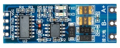
This IC supports half-duplex communication, allowing data to be transmitted and received over a single pair of wires, though not simultaneously. It includes driver enable and receiver enable pins, which can be controlled to switch between transmitting and receiving modes. It is a half-duplex driver with a Unit Load (UL) rating of 1 and therefore you can have up to 32 MAX485s on a single RS-485 bus.
You can learn more about RS-485 communication using the following tutorials:
RS485 Temperature and Humidity Sensor
This is one of the temperature humidity sensors that work on the Standard Modbus RTU protocol.

We will be using this sensor in this guide. We will interface the temperature humidity sensor with Arduino & using the RS-485 we can use standard Modbus RTU to read the sensor data.
Product Specifications

- Power Supply: 5-30V DC
- Maximum Power Consumption: ≤ 5W
- Humidity Range: 0-100% RH
- Temperature Range: -40° to 80° C
- Accuracy: Temperature ± 0.3 °C; Humidity ± 0.3% RH
- Communication Protocol: Standard Modbus RTU
- Communication Mode: 485 communication
- Baud Rate: 9600 (default), 1200, 2400, 4800, 9600, 19200 (can be set by software)
- Default Address of Equipment: Default 1 (1~254 can be modified by software)
- Register: Humidity address 0, temperature address 1 (software modifiable)
- Wiring Mode: Red+, black GND, Yellow A+, Green B-
Communication Protocol Details
- Basic Communication Parameters
| Parameter | Specification |
|---|---|
| Coding | 8 bit binary |
| Data Bits | 8bit |
| Parity Bit | None |
| Stop Bit | 1bit |
| Error Checking | CRC (redundant cyclic code) |
| Baud Rate | 1200bit/s, 2400bit/s, 4800bit/s, 9600 bit/s, 14400 bit/s, 19200 bit/s (Factory default is 9600bit/s) |
- Data Frame Format Definition
| Component | Specification |
|---|---|
| Initial Structure | ≥ 4 bytes of time |
| Address Code | 1 byte |
| Function Code | 1 byte |
| Data Area | N bytes |
| Error Check | 16-bit CRC code |
| Time to End Structure | ≥ 4 bytes |
Address code: the address of the transmitter, which is unique in the communication network (factory default 0x01).
Function code: the function instruction of the command sent by the host, this transmitter only uses the function code 0x03 (read register data).
Data area: The data area is the specific communication data, pay attention to the high byte of the 16 bits data first!
CRC code: two-byte check code.
Host Query Frame Structure:
| Component | Address Code | Function Code | Register Start Address | Register Length | Check Code Low | Check Code High |
|---|---|---|---|---|---|---|
| Size | 1 byte | 1 byte | 2 bytes | 2 bytes | 1 byte | 1 byte |
Slave Acknowledgment Frame Structure:
| Component | Address Code | Function Code | Number of Valid Bytes | Data Area | Second Data Area | Check Code |
|---|---|---|---|---|---|---|
| Size | 1 byte | 1 byte | 1 byte | 2 bytes | 2 bytes | 2 bytes |
- Register Address
| Register Address (Hex) | PLC or Configuration Address | Content | Operate | Support Function Code |
|---|---|---|---|---|
| 0000 H | 40001 | Humidity (10 times the actual value) | Read only | 03 |
| 0001 H | 40002 | Temperature (10 times the actual value) | Read only | 03 |
| 0100H | 40257 | Baud rate address | Read and write | 03, 06 |
| 0102 H | 40259 | Humidity address | Read and write | 03, 06 |
| 0104H | 40260 | Temperature correction value | Read and write | 03, 06 |
| 0105H | 40261 | Humidity correction value | Read and write | 03, 06 |
Read the Temperature and Humidity Value of Device Address 0x01
Query Frame (hexadecimal):
| Address Code | Function Code | Initial Address | Data Length | Check Code Low | Check Code High |
|---|---|---|---|---|---|
| 0x01 | 0x03 | 0x00 0x02 | 0x00 0x02 | 0xC4 | 0x08 |
Response Frame (hexadecimal): (For example, the temperature is -9.7°C and the humidity is 48.6%RH)
| Address Code | Function Code | Number of Valid Bytes | Humidity Value | Temperature Value | Check Code Low | Check Code High |
|---|---|---|---|---|---|---|
| 0x01 | 0x03 | 0x04 | 0x01 E6 | 0xFF 0x9F | 0x1B | 0xA0 |
Temperature Calculation: When the temperature is lower than 0 °C, the temperature data is uploaded in the form of complement code. Temperature: FF9F H (hex) = -97 => Temperature = -9.7°C
Humidity Calculation: Humidity: 1E6 H (Hex) = 486 => Humidity = 48.6%RH
How to use Modbus RTU with Raspberry Pi Pico & MicroPython
Now let’s dive into the practical aspects. In this section, we will learn how to connect a humidity and temperature sensor to a Raspberry Pi Pico using RS485 and program the Pico for communication using the Modbus RTU protocol.
First, we’ll establish the hardware connections using specified pins on the Raspberry Pi Pico. After setting up the physical connections, we’ll move on to writing code in MicroPython for the Pico, enabling Modbus RTU communication.
Hardware Setup & Connection
Here is the connection diagram between Raspberry Pi Pico, RS485 and Modbus RTU based Sensor.

In this connection, we will use UART0 of Raspberry Pi Pico for Serial Communication with RS485. Connect the Tx and Rx of MAX485 with GP0 and GP1 of the Raspberry Pi Pico. Power the MAX485 Module with a 3.3V or 5V supply.
Similarly, for the Temperature and Humidity Sensor part, connect the A+ of MAX485 to the Yellow Wire (A+) of the Sensor. Connect the B- of MAX485 to the Green Wire (B-) of the Sensor. Power the sensor with 5V Power supply.

You may simply use a connecting wire and breadboard for this setup. The above image is the example how I set the connection. Finally connect the Raspberry Pi Pico to your computer using the micro-USB Cable to power it on.
Source Code/Program
Lets move to the programming part of the Modbus RTU Communication using Raspberry Pi Pico & RS485 Module. The code doesn’t use any standard Modbus library. Rather the whole code is written for direct communication with between master and slave device.
This Python script configures a Raspberry Pi Pico to function as a Modbus RTU master using UART for serial communication to read humidity and temperature data from a Modbus slave device.
It includes functions to construct and send Modbus requests, read responses, verify their CRC for data integrity, and process the received data to calculate and display humidity and temperature readings. The script also handles repeated communication in a loop, managing errors related to CRC and response reception.
|
1 2 3 4 5 6 7 8 9 10 11 12 13 14 15 16 17 18 19 20 21 22 23 24 25 26 27 28 29 30 31 32 33 34 35 36 37 38 39 40 41 42 43 44 45 46 47 48 49 50 51 52 53 54 55 56 57 58 59 60 61 62 63 64 65 66 67 68 69 70 71 72 73 74 75 76 77 78 |
from machine import UART, Pin import time # Define UART pins TX_PIN = 0 RX_PIN = 1 # Initialize UART for Modbus communication uart = UART(0, baudrate=9600, tx=Pin(TX_PIN), rx=Pin(RX_PIN)) # Define Modbus parameters slave_address = 0x01 # Address of the Modbus slave device function_code = 0x03 # Function code to read holding registers start_address_high = 0x00 # High byte of the starting address start_address_low = 0x00 # Low byte of the starting address register_count_high = 0x00 # High byte of the number of registers to read register_count_low = 0x02 # Low byte of the number of registers to read def calculate_crc(frame): crc = 0xFFFF for pos in frame: crc ^= pos for _ in range(8): if crc & 0x0001: crc >>= 1 crc ^= 0xA001 else: crc >>= 1 return crc def construct_modbus_request(address, function, start_high, start_low, count_high, count_low): frame = [address, function, start_high, start_low, count_high, count_low] crc = calculate_crc(frame) frame.append(crc & 0xFF) # CRC low byte frame.append((crc >> 8) & 0xFF) # CRC high byte return bytes(frame) def send_modbus_request(frame): uart.write(frame) def read_modbus_response(length): response = uart.read(length) return response def verify_crc(frame): received_crc = (frame[-1] << 8) | frame[-2] calculated_crc = calculate_crc(frame[:-2]) return received_crc == calculated_crc def process_modbus_response(frame): humidity = (frame[3] << 8) | frame[4] temperature = (frame[5] << 8) | frame[6] humidity_value = humidity / 10.0 temperature_value = temperature / 10.0 print(f"Humidity: {humidity_value} %RH") print(f"Temperature: {temperature_value} °C") print() def main(): while True: request_frame = construct_modbus_request(slave_address, function_code, start_address_high, start_address_low, register_count_high, register_count_low) send_modbus_request(request_frame) time.sleep(1) # Wait for the response response_length = 9 # Expected response length if uart.any(): response_frame = read_modbus_response(response_length) if response_frame and verify_crc(response_frame): process_modbus_response(response_frame) else: print("CRC error.") else: print("No response from slave.") time.sleep(2) # Wait before sending the next request if __name__ == "__main__": main() |
Copy the above code to the editor window of your Thonny IDE. Select the Raspberry Pi Pico and the correct COM port. Then run the code.
Once the code runs, observe the terminal window. You will be see the temperature and humidity data displayed correctly.

This is how you can implement the Modbus protocol with Raspberry Pi Pico microcontroller with MicroPython code to read the sensor register data.
This setup lets you successfully read data from sensors, making it a practical guide for anyone looking to integrate Raspberry Pi Pico with Modbus RTU based industrial systems for monitoring and controlling devices.
Video Tutorial & Guide

You may follow the same tutorial with Arduino & ESP32:


