
")
Overview
In this guide, we will interface the XBee Module with Arduino & set up ZigBee communication to use it as a transmitter and receiver. ZigBee is a wireless communication protocol designed primarily for IoT (Internet of Things) applications. It helps smart devices to easily connect and communicate with each other in a mesh network. This mesh structure means that ZigBee devices can pass data through one another, which extends the network’s range and increases reliability.

In this tutorial, we will:
- Introduce the XBee Module: Learn about its features, applications, and range.
- Set Up XCTU Software: Use XCTU to configure the XBee module as a transmitter or receiver.
- Connect XBee Modules to Arduino: Set up one Arduino board with an XBee module as a transmitter and another as a receiver.
- Write Sample C++ Code: Create code to send data wirelessly between the two Arduino boards.
- Integrate a Sensor: Attach a sensor to the transmitter and modify the C++ code to send sensor data wirelessly.
- Test the Wireless Communication: Verify that data is successfully transmitted between the transmitter and receiver over a certain distance.
By the end, you’ll have a fully functional setup for wireless ZigBee communication using XBee Module and Arduino.
Components Required
We need the following components for this tutorial. You can purchase the components either from Amazon or AliExpress.
| S.N. | Components Name | Quantity | Purchase Link |
|---|---|---|---|
| 1 | Arduino UNO Board | 2 | Amazon | AliExpress |
| 2 | XBee Module | 2 | Amazon | AliExpress |
| 3 | Xbee Adapter | 2 | Amazon | AliExpress |
| 4 | DHT11 Sensor | 1 | Amazon | AliExpress |
| 5 | 16x2 I2C LCD | 1 | Amazon | AliExpress |
| 6 | Connecting Wires | 10 | Amazon | AliExpress |
| 7 | Breadboard | 2 | Amazon | AliExpress |
Zigbee Communication
Zigbee is a short-range wireless protocol, similar to Wi-Fi and Bluetooth, designed to support low-cost, battery-operated IoT applications where extending battery life is crucial. Built on the IEEE 802.15.4 physical layer, Zigbee provides a reliable, energy-efficient communication solution by operating at a low data rate of 250 Kbps on a standard frequency of 2.4 GHz. This lower data rate is an intentional trade-off that enables a power-saving, low-bandwidth network capable of supporting many connected devices.
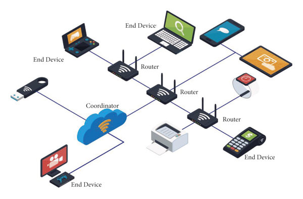
A single Zigbee device typically covers a range of 10-20 meters indoors, enabling it to locate and connect with other Zigbee devices in the network. Unlike Bluetooth, which relies on direct, point-to-point connections, Zigbee uses a mesh network topology. This mesh setup allows Zigbee devices to relay messages across multiple intermediary devices, expanding the network’s coverage and improving its resilience.
For example, consider a Zigbee-enabled light bulb and a Zigbee-enabled light switch. When both devices are connected within the same network, they can “speak” the same protocol language, allowing the switch to control the bulb without additional configuration.
Device Types in a Zigbee Network
In a Zigbee network, there are three main types of devices, each playing a specific role:
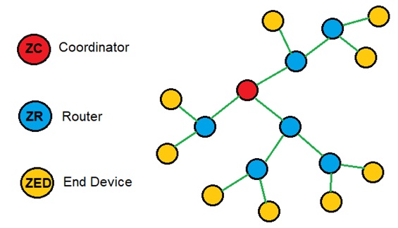
- Coordinator: The coordinator is the primary device that initiates the Zigbee network. It handles essential tasks like assigning network addresses, managing settings, and securing communications through encryption. Only one coordinator is required in a Zigbee network.
- Router: Routers extend the network’s range by passing data between devices. They connect with other routers or end devices, creating multiple communication pathways, which strengthens the network.
- End Device: End devices are typically low-power devices such as sensors, smart bulbs, or switches. They connect directly to a router or coordinator and do not relay data, helping to conserve energy. End devices are often battery-operated and can enter sleep mode when inactive to preserve power.
Differences Between ZigBee & XBee
Both “XBee” and “Zigbee” are correct terms, but they refer to different things:
- Zigbee: This is a wireless communication protocol standard designed for low-power IoT applications, enabling devices to connect in a mesh network. It’s a protocol used by many devices and manufacturers.
- XBee: This is a product line from Digi International that includes modules capable of supporting various wireless protocols, including Zigbee.
In short, Zigbee is the protocol, and XBee is a specific hardware product that can support Zigbee and other protocols.
XBee Module
XBee modules are popular wireless communication modules developed by Digi International, designed to make wireless networking easy for IoT and embedded applications.

They offer a range of connectivity options and configurations, providing users with flexible, reliable wireless solutions. They are compatible with multiple protocols, including Zigbee, 802.15.4, Wi-Fi, and cellular.
Key Features of XBee Modules
- Protocol Support: XBee modules are versatile, with support for multiple protocols. The most common XBee modules use Zigbee, based on the IEEE 802.15.4 standard, but Digi offers versions supporting 802.11 (Wi-Fi) and LTE cellular networks, allowing XBee modules to meet a wide range of application needs.
- Communication Topologies: XBee modules support various network topologies, including:
- Point-to-Point: Direct communication between two XBee devices.
- Point-to-Multipoint: A single XBee device communicates with multiple devices.
- Mesh Network: Using Zigbee, XBee modules can create robust, self-healing mesh networks, which enhance coverage by allowing messages to be relayed through multiple nodes.
- Source and Destination Addressing: XBee modules offer advanced addressing capabilities, enabling both unicast and broadcast communications. This means you can target a specific device in the network or broadcast messages to multiple devices simultaneously, making them flexible for complex network designs.
- DSSS Modulation: XBee modules use Direct Sequence Spread Spectrum (DSSS) modulation. DSSS helps improve resistance to interference, provides secure data transmission, and minimizes packet collisions.
- Built-in I/O and ADC: In addition to wireless communication, many XBee modules have built-in digital and analog input/output capabilities. With 10-bit ADCs, digital I/O pins, and PWM outputs, XBee modules can interface directly with sensors, actuators, and microcontrollers, reducing the need for additional hardware.
- Serial and SPI Interface: XBee modules primarily use UART for serial communication, allowing easy integration with microcontrollers and computers. Some models, like the XBee S2C, also support SPI, which provides a faster communication interface suitable for applications requiring high-speed data exchange.
- Long Range and Power Options: With a range that can extend from 10-100 meters indoors to over a kilometer outdoors (in line-of-sight conditions), XBee modules can be configured for low-power or high-power transmission to suit battery-operated or power-sensitive applications.
- XCTU Configuration Software: Digi provides XCTU, a free software tool, for configuring and testing XBee modules. With XCTU, users can set network parameters, assign addresses, and monitor network activity in real time, simplifying the setup and troubleshooting process.
XBee Module Pinout
The XBee module has 20 pins, each serving specific functions that support various I/O, communication, and control features.

| Pin No. | Name | Direction | Description |
|---|---|---|---|
| 1 | VCC | – | Power Supply |
| 2 | DOUT | Output | UART Data Out |
| 3 | DIN/CONFIG | Input | UART Data In |
| 4 | DO8 | Output | Digital Output 8 |
| 5 | RESET | Input | Module Reset (reset pulse >= 200 ns) |
| 6 | PWM0/RSSI | Output | PWM Output 0 / Received Signal Strength Indicator |
| 7 | PWM1 | Output | PWM Output 1 |
| 8 | Reserved | – | Do not connect |
| 9 | DTR/SLEEP_RQ/DI8 | Input | Sleep Control or Digital Input 8 |
| 10 | GND | – | Ground |
| 11 | AD4/DIO4 | Input / Output | Analog Input 4 / Digital I/O 4 |
| 12 | CTS/DIO7 | Input / Output | Clear-To-Send Flow Control or Digital I/O 7 |
| 13 | ON/SLEEP | Output | Module Status Indicator, High = ON, Low = SLEEP |
| 14 | VREF | Input | Reference Voltage for ADC |
| 15 | ASSOCIATE/AD5/DIO5 | Input / Output | Association Indicator, Analog Input 5 or Digital I/O 5 |
| 16 | RTS/AD6/DIO6 | Input / Output | Request-To-Send Flow Control, Analog Input 6 or Digital I/O 6 |
| 17 | AD3/DIO3 | Input / Output | Analog Input 3 or Digital I/O 3 |
| 18 | AD2/DIO2 | Input / Output | Analog Input 2 or Digital I/O 2 |
| 19 | AD1/DIO1 | Input / Output | Analog Input 1 or Digital I/O 1 |
| 20 | AD0/DIO0 | Input / Output | Analog Input 0 or Digital I/O 0 |
XBee USB Adapter Board
One disadvantage of the Zigbee module is its lack of breadboard compatibility; its pin mapping doesn’t align with typical breadboards. Additionally, most Zigbee modules operate within a voltage range of 2.0V to 3.6V, with 3.3V as the standard. This makes them incompatible with 5V microcontrollers or any microcontrollers with higher voltage digital pins.

To overcome this, a Zigbee Adapter is needed. A popular choice is the XBee USB Adapter, a UART communication board designed specifically for XBee connectivity. It provides a UART interface, USB interface, and includes onboard buttons and LEDs, making it a user-friendly option for both development and debugging.
Key Features of the XBee USB Adapter
- Compatibility with Microcontrollers: The adapter operates with 3.3V logic, making it compatible with Arduino and other 3.3V microcontrollers.
- USB Interface: Equipped with a USB port, the adapter enables direct communication with a computer, allowing configuration and testing using AT Commands.
- Testing and Debugging: The adapter includes buttons and LEDs that facilitate easy testing of XBee modules.
Using XBee Module with XBee Adapter Board
To use the Zigbee module, start by carefully inserting it into the adapter board, ensuring the correct alignment and orientation.

The module should fit securely on top of the adapter, so double-check that the pins are properly aligned to avoid any connection issues.
Setting Up XBee Module using the X-CTU Software
Digi International provides a software tool known as X-CTU for configuring XBee in either operating mode or device function type. Using this tool, we can configure the device, test its performance, and upgrade its firmware.
Here we need to first download X-CTU and go through a short overview of the X-CTU User Guide.

Follow these steps to configure two Zigbee modules—one as the coordinator and the other as the end device—using the X-CTU software.

Configure the Coordinator
- Connect the ZigBee Module: Plug the ZigBee module into your computer using a USB cable and note the COM port assigned to it.
- Open X-CTU Software: Launch the X-CTU software, then click on the Add Device option.

- Select COM Port: Choose the appropriate COM port for your connected ZigBee module and click Next. No additional settings need to be changed here, so click Finish to begin searching for the module.
- Add the Detected Device: When X-CTU detects your module, select it and click Add Selected Device. This will open the module’s configuration page.
- Update Firmware (if prompted): If X-CTU suggests a firmware update, proceed with the upgrade to ensure your module is using the latest version.
- Set Device as Coordinator:
- Under Radio Settings, change the PAN ID to a unique identifier, like
10001. This ID must match on all devices in the network. - Scroll down and set the Device Role to Coordinator.

- Under Radio Settings, change the PAN ID to a unique identifier, like
- Write Settings: Click on Write to save these changes to the module. Your coordinator is now configured.


Configure the End Device
- Connect the Second ZigBee Module: Insert the second ZigBee module into your computer, following the same process as above.
- Select COM Port: Once connected, choose the appropriate COM port in X-CTU, click Next, and then Finish to start device detection.
- Add the Detected Device: Once the device is found, select it and add it to the software. If a firmware update is prompted, proceed to update.
- Set Device as End Device:
- In Radio Settings, set the PAN ID to match the one set on the coordinator (e.g.,
10001). - Scroll down and set the Device Role to End Device instead of Coordinator.

- In Radio Settings, set the PAN ID to match the one set on the coordinator (e.g.,
- Write Settings: Click Write to save these settings to the module. Your end device is now configured.

Once these steps are completed, your ZigBee modules are set up, with one as a coordinator and the other as an end device, and are ready for communication.
Interfacing XBee Module with Arduino
Now let us interface XBee Module with Arduino Board. Basically we will be connecting the XBee Module Arduino so that we can establish the ZigBee wireless communication between coordinator (receiver) and end device (transmitter).
Here is a connection diagram between Arduino & XBee Adapter.

Connect the VCC & GND of XBee Module to 5V & GND of Arduino respectively. Similarly, connect the Tx & Rx of XBee Adapter to D11 & D10 of Arduino respectively.

You may connect the XBee Adapter Board directly using the jumper wires. As we need both transmitter & receiver circuit, we need to do the same connection for pair of boards.
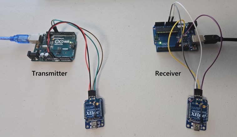
That’s the final hardware setup part to start with the Arduino ZigBee communication demo.
Source Code/Program for Arduino ZigBee Communication
After setting up the hardware part, we can take a look at the pair of Arduino code that can establish ZigBee communication between two Arduino board using the XBee Module.
Sender Code (End Device)
This code sets up serial communication between an Arduino and XBee module. Then it continuously generates a random number between 0 and 255. It then sends it to the XBee module with markers (< and >) around each number. It also displays the sent number in the Serial Monitor for debugging purposes.
|
1 2 3 4 5 6 7 8 9 10 11 12 13 14 15 16 17 18 19 20 21 22 23 |
#include <SoftwareSerial.h> // Include SoftwareSerial library for communication SoftwareSerial XBee(10, 11); // Define SoftwareSerial pins: RX = 10, TX = 11 void setup() { Serial.begin(9600); // Start communication with the PC for debugging XBee.begin(9600); // Start communication with the XBee module randomSeed(analogRead(0)); // Seed the random number generator for varied results } void loop() { int randomNumber = random(256); // Generate a random number between 0 and 255 XBee.print('<'); // Start of transmission marker XBee.print(randomNumber); // Send the randomly generated number XBee.println('>'); // End of transmission marker Serial.print("Sent number: "); // Debugging output to Serial Monitor Serial.println(randomNumber); delay(1000); // Delay between sends to avoid flooding } |
Receiver Code (Coordinator Device)
This code reads and processes messages from an XBee module, capturing data between markers < and >. When a complete message is received, it converts the message to an integer and displays it on the Serial Monitor for debugging.
|
1 2 3 4 5 6 7 8 9 10 11 12 13 14 15 16 17 18 19 20 21 22 23 24 25 26 27 28 29 30 31 32 33 34 35 36 37 38 39 40 41 42 43 44 |
#include <SoftwareSerial.h> // Include SoftwareSerial library for communication SoftwareSerial XBee(10, 11); // Define SoftwareSerial pins: RX = 10, TX = 11 bool started = false; // True when start marker is detected bool ended = false; // True when end marker is detected char incomingByte; // Storage for each byte read char msg[4]; // Array to assemble the incoming message byte index = 0; // Current position in the array void setup() { Serial.begin(9600); // Start communication with the PC for debugging XBee.begin(9600); // Start communication with the XBee module } void loop() { while (XBee.available() > 0) { // Check if there is data available from the XBee incomingByte = XBee.read(); // Read the incoming byte if (incomingByte == '<') { // Detect start of the message started = true; index = 0; msg[index] = '\0'; // Clear the buffer } else if (incomingByte == '>') { // Detect end of the message ended = true; break; // Stop reading, process the message } else if (started && index < 3) { // Store the byte in msg array if message has started msg[index] = incomingByte; index++; msg[index] = '\0'; // Null terminate the string } } if (started && ended) { // If a complete message was received, process it int value = atoi(msg); // Convert the buffer to an integer Serial.print("Received number: "); // Debugging output to Serial Monitor Serial.println(value); started = false; // Reset for the next message ended = false; } } |
Upload both these codes to the respective Arduino board. This means the coordinator and the end device.
After uploading is done, open the Serial Monitor.
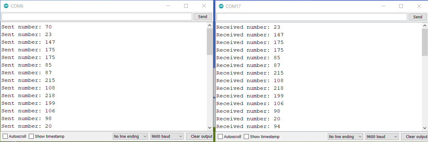
As you can see whatever the message is sent by the sender, the same message is received by the receiver.
This is amazing right? So we have successfully established the communication between two ZigBee devices.
Sending Sensor Data over ZigBee Communication
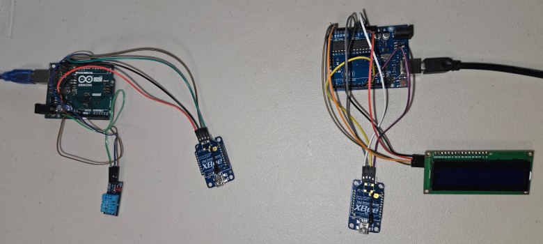
In this example, we will send the DHT11 Humidity and Temperature data wirelessly from Sender (end device) to the receiver (coordinator). First we will setup the hardware. Then we will modify the sender and receiver code for both Arduino boards.
Hardware Set up and Connection
Now let’s connect this DHT11 Sensor to the sender side. Connect the VCC, GND & Output pin of the DHT11 Sensor to the 3.3V, GND & D2 of the Arduino board respectively.

On the receiver side, connect the 16×2 I2C LCD Display which will print the DHT11 Sensor data received wirelessly.

You can use the jumper wires to connect the DHT11 and LCD Display as you see the hardware setup here.
Sender Code (End Device)
This code reads temperature and humidity data from a DHT11 sensor and sends the values to an XBee module, encapsulating them within markers < and > for easy identification. The data is also displayed on the Serial Monitor for debugging.
|
1 2 3 4 5 6 7 8 9 10 11 12 13 14 15 16 17 18 19 20 21 22 23 24 25 26 27 28 29 30 31 32 33 34 35 36 37 38 |
#include <SoftwareSerial.h> #include <DHT.h> SoftwareSerial XBee(10, 11); // Define SoftwareSerial pins: RX = 10, TX = 11 #define DHTPIN 2 // Define pin connected to the DHT sensor #define DHTTYPE DHT11 // Define the type of DHT sensor DHT dht(DHTPIN, DHTTYPE); // Initialize DHT sensor void setup() { Serial.begin(9600); // Start communication with the PC for debugging XBee.begin(9600); // Start communication with the XBee module dht.begin(); // Initialize the DHT11 sensor } void loop() { float h = dht.readHumidity(); // Read humidity float t = dht.readTemperature(); // Read temperature // Check if any reads failed and exit early (to try again). if (isnan(h) || isnan(t)) { Serial.println("Failed to read from DHT sensor!"); return; } XBee.print("<T:"); // Start of transmission marker with temp label XBee.print(t); // Send the temperature XBee.print(",H:"); // Separator with humidity label XBee.print(h); // Send the humidity XBee.println(">"); // End of transmission marker Serial.print("Sent Temp: "); // Debugging output to Serial Monitor Serial.print(t); Serial.print("C, Hum: "); Serial.print(h); Serial.println("%"); delay(2000); // Delay between sends to avoid flooding } |
Receiver Code (Coordinator Device)
This code reads temperature and humidity data transmitted from an XBee module, extracts these values, and displays them on a 16×2 I2C LCD screen while also printing them to the Serial Monitor for debugging.
|
1 2 3 4 5 6 7 8 9 10 11 12 13 14 15 16 17 18 19 20 21 22 23 24 25 26 27 28 29 30 31 32 33 34 35 36 37 38 39 40 41 42 43 44 45 46 47 48 49 50 51 52 53 54 55 56 57 58 59 60 61 62 63 64 65 66 67 68 69 70 71 72 73 74 75 |
#include <SoftwareSerial.h> #include <LiquidCrystal_I2C.h> SoftwareSerial XBee(10, 11); // Define SoftwareSerial pins: RX = 10, TX = 11 LiquidCrystal_I2C lcd(0x27, 16, 2); // Set the LCD address to 0x27 for a 16 chars and 2 line display bool started = false; // True when start marker is detected bool ended = false; // True when end marker is detected char incomingByte; // Storage for each byte read char msg[32]; // Array to assemble the incoming message byte index = 0; // Current position in the array void setup() { Serial.begin(9600); // Start communication with the PC for debugging XBee.begin(9600); // Start communication with the XBee module lcd.init(); // Initialize the LCD lcd.backlight(); // Turn on the backlight } void loop() { while (XBee.available() > 0) { incomingByte = XBee.read(); // Read the incoming byte if (incomingByte == '<') { started = true; index = 0; msg[index] = '\0'; // Clear the buffer } else if (incomingByte == '>') { ended = true; break; } else if (started && index < 31) { msg[index] = incomingByte; index++; msg[index] = '\0'; } } if (started && ended) { Serial.print("Raw Msg: "); // Print raw message for debugging Serial.println(msg); // Extract temperature and humidity manually char* tempPtr = strstr(msg, "T:"); // Find the start of the temperature string char* humPtr = strstr(msg, "H:"); // Find the start of the humidity string if (tempPtr && humPtr) { float temp = atof(tempPtr + 2); float hum = atof(humPtr + 2); // Print to LCD lcd.setCursor(0, 0); lcd.print("Temp: "); lcd.print(temp); lcd.print(" C"); lcd.setCursor(0, 1); lcd.print("Hum: "); lcd.print(hum); lcd.print(" %"); // Print to Serial Monitor for debugging Serial.print("Received Temp: "); Serial.print(temp); Serial.print(" C, Humi: "); Serial.print(hum); Serial.println(" %"); } else { Serial.println("Failed to parse temp and humidity."); } started = false; // Reset for the next message ended = false; } } |
Upload the code again to both the sender and receiver. Then open the Serial Monitor.
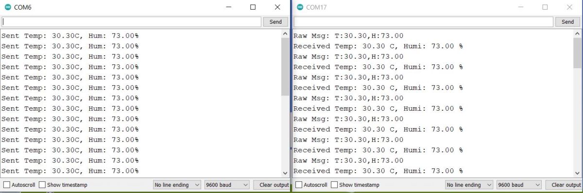
The Serial Monitor will show the value of temperature and humidity continuously.
Similarly, the LCD also displays the temperature and humidity readings wirelessly.
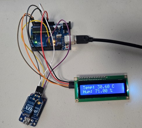
This is great again. We can use this technique multiple times to send any sensor data wirelessly over ZigBee protocol using Arduino & XBee Module. You may write a MicroPython Code to establish wireless ZigBee communication with Raspberry Pi Pico & XBEE Module.
Video Tutorial & Guide


")


1 Comment
Hi I managed to transmit data but I couldn’t receive it although I followed all your instructions