

Overview
This tutorial is about RS-485 Full-Duplex Communication using MAX485 & Arduino. In our previous article, we learned how to implement RS-485 Simplex Communication as well as Half-Duplex Communication using the MAX485 IC with Arduino. This tutorial will introduce you to Full-Duplex RS-485 communication, which allows two-way communication over the same pair of wires simultaneously.
The MAX485 IC is not only capable of Simplex but also adept at Full-Duplex communication, making it a versatile choice for projects involving RS-485 protocols. In this tutorial, we’ll set up an Arduino-based RS-485 network using MAX485 chips to demonstrate how devices can simultaneously send and receive messages.
We will provide a detailed wiring diagram to connect your Arduino boards using MAX485 modules for Full-Duplex communication. We’ll write and explain Arduino code to handle sending and receiving data.
Bill of Materials
We need the following components for this tutorial.
| S.N. | Components Name | Quantity | Purchase Link |
|---|---|---|---|
| 1 | Arduino Nano Board | 2 | Amazon | AliExpress |
| 2 | MAX485 Modbus Module | 4 | Amazon | AliExpress |
| 3 | Connecting Wires | 30 | Amazon | AliExpress |
| 4 | Breadboard | 2 | Amazon | AliExpress |
MAX485 Module

The MAX485 IC is a low-power transceiver designed for RS-485 communication. It is widely used in industrial and commercial applications for robust, long-distance data transmission.

It operates on a 5V power supply and features both differential signaling and high noise immunity, making it ideal for environments with significant electrical interference. The MAX485 can achieve communication speeds of up to 2.5 Mbps over distances of up to 1200 meters, providing reliable and efficient data exchange.
This IC supports half-duplex communication, allowing data to be transmitted and received over a single pair of wires, though not simultaneously. It includes driver enable and receiver enable pins, which can be controlled to switch between transmitting and receiving modes. It is a half-duplex driver with a Unit Load (UL) rating of 1 and therefore you can have up to 32 MAX485s on a single RS-485 bus.
Specifications of MAX485 Module
- Configuration: Half-Duplex
- Data Rate: Up to 2.5 Mbps
- Data Rate at 1200 m: 110 Kbps
- Slew-rate Limited: No
- Quiescent Current: 300 µA
- Number of Receivers on the Bus: 32
- Pin Count: 8
- Working Voltage: 5V
- Driver Output Voltage Range: -7V to +12V
- Receiver Input Sensitivity: ±200 mV
- Receiver Input Voltage Range: -7V to +12V
- Thermal Shutdown Protection: Yes
- ESD Protection: ±15 kV (Human Body Model)
- Propagation Delay: 50 ns (Typical)
- Operating Temperature Range: -40°C to +85°C
- Package Types: PDIP, SOIC, and TSSOP
- Enable/Disable Time: 600 ns (Typical for driver enable), 200 ns (Typical for receiver enable)
- Short-circuit Current: 250 mA (Driver)
MAX485 Pinout Table

| Pin Number | Pin Name | Description |
| 1 | RO | Receiver Output: Outputs the received data to the microcontroller. |
| 2 | RE | Receiver Enable: Enables (low) or disables (high) the receiver. |
| 3 | DE | Driver Enable: Enables (high) or disables (low) the driver. |
| 4 | DI | Driver Input: Takes input data to be transmitted over the RS-485 bus. |
| 5 | GND | Ground: Provides the ground reference for the IC. |
| 6 | A | Non-inverting Driver Output/Receiver Input: One of the differential signal lines for RS-485 communication. |
| 7 | B | Inverting Driver Output/Receiver Input: The other differential signal line for RS-485 communication. |
| 8 | VCC | Power Supply: Should be connected to a 5V power source. |
MAX485 Module Schematic
The provided schematic shows how to set up RS-485 communication using the MAX485 IC, which helps in converting regular UART signals to differential signals. This conversion is important because differential signals can travel longer distances with less noise interference.

The design includes a 120Ω termination resistor (R7) between the A and B lines to match the bus impedance, which helps in reducing signal reflections and maintaining clear communication. Additionally, 20kΩ pull-up (R6) and pull-down (R5) resistors keep the A and B lines stable, preventing them from picking up noise when not in use.
For power stability, the schematic uses capacitors C1 (10µF) and C2 (0.1µF) to filter out any noise from the power supply, ensuring the MAX485 IC operates smoothly. An LED (D1) with a 1kΩ resistor (R8) is included to indicate when the circuit is powered, making it easier to troubleshoot and confirm that the device is on and working.
Achieving Full-Duplex Communication in RS-485 (MAX485)
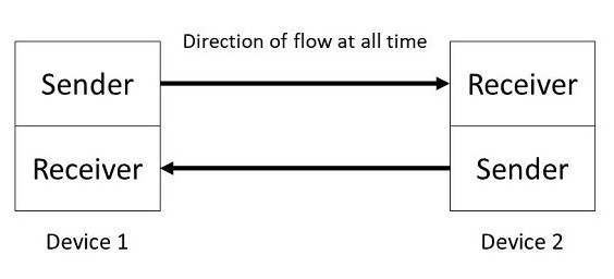
In Full-Duplex communication mode, data can flow in both directions between devices simultaneously. This setup is common in systems where continuous bi-directional information sharing is required, such as in real-time communication and interactive systems.
The MAX485 IC is only designed to handle half-duplex communication, means either it can transmit or receive data one at a time.
To achieve full-duplex communication in RS-485 using the MAX485 IC, you need to use two MAX485 modules per device: one dedicated to transmitting (TX) and the other to receiving (RX). This setup allows simultaneous two-way data transfer over two pairs of wires. Each device will use one pair of wires for transmitting data and another pair for receiving data, enabling both devices to communicate with each other in real-time without waiting for the line to be clear.
In a full-duplex RS-485 configuration, the transmitting module’s Driver Enable (DE) and Receiver Enable (RE) pins are managed to control when the device is sending data. The DE pin is set high to enable the driver for data transmission, while the RE pin is set low to disable the receiver during this time.
Conversely, the receiving module’s DE pin is set low to disable its driver, and the RE pin is set low to enable the receiver, allowing it to continuously listen for incoming data. This way, both the transmitter and receiver can operate independently, with the transmitter constantly sending data and the receiver continuously listening and processing incoming data.
MAX485 Arduino Full-Duplex Communication Hardware Setup
The circuit and connection diagram to achieve a full-duplex communication in MAX485 IC using Arduino is given below. Follow the schematic for connection diagram.

Arduino 1 (Left Side in the Diagram)
Transmitting Module (Top MAX485):
- DE (Driver Enable): Connected to GND.
- RE (Receiver Enable): Connected to a digital pin (e.g., D2) to control the reception.
- DI (Driver Input): Not Connected.
- RO (Driver Output): Connected to the TX pin (D11) of Arduino 1.
- A and B Pins: Connected to the A and B lines of the RS-485 bus for transmitting data.
- VCC: Connected to 5V.
- GND: Connected to GND.
Receiving Module (Bottom MAX485):
- DE (Driver Enable): Connected to a digital pin (e.g., D3) to control the reception.
- RE (Receiver Enable): Connected to GND.
- DI (Driver Input): Connected to the RX pin (D10) of Arduino 1.
- RO (Driver Output): Not Connected.
- A and B Pins: Connected to the A and B lines of the RS-485 bus for receiving data.
- VCC: Connected to 5V.
- GND: Connected to GND.
Arduino 2 (Right Side in the Diagram)
Transmitting Module (Top MAX485):
- DE (Driver Enable): Connected to GND.
- RE (Receiver Enable): Connected to a digital pin (e.g., D2) to control the reception.
- DI (Driver Input): Not Connected.
- RO (Driver Output): Connected to the TX pin (D11) of Arduino 2.
- A and B Pins: Connected to the A and B lines of the RS-485 bus for transmitting data.
- VCC: Connected to 5V.
- GND: Connected to GND.
Receiving Module (Bottom MAX485):
- DE (Driver Enable): Connected to a digital pin (e.g., D3) to control the reception.
- RE (Receiver Enable): Connected to GND.
- DI (Driver Input): Connected to the RX pin (D10) of Arduino 2.
- RO (Driver Output): Not Connected.
- A and B Pins: Connected to the A and B lines of the RS-485 bus for receiving data.
- VCC: Connected to 5V.
- GND: Connected to GND.

Sender/Receiver Code
Here is the sender and receiver code for setting MAX485 IC with Arduino for full-duplex communication.
This code sets up full-duplex communication using RS-485, allowing both Arduino 1 and Arduino 2 to send and receive data simultaneously. The DE and RE pins are used to control the transmission and reception modes of the MAX485 module. When data is available from the serial monitor, the code sets the DE pin high to enable the driver and the RE pin high to disable the receiver, allowing the Arduino to send data over the RS-485 bus.
After sending the data, the DE pin is set low to disable the driver, and the RE pin is set low to enable the receiver. The code then checks if there is any data available on the RS-485 bus. If data is available, it reads the data and prints it to the serial monitor. This setup ensures that both Arduinos can communicate with each other in a full-duplex manner, simultaneously handling sending and receiving operations.
|
1 2 3 4 5 6 7 8 9 10 11 12 13 14 15 16 17 18 19 20 21 22 23 24 25 26 27 28 29 30 31 32 33 34 35 36 37 38 39 40 41 42 43 44 45 |
#include <SoftwareSerial.h> #define DE_PIN 2 // Pin to control DE (Driver Enable) #define RE_PIN 3 // Pin to control RE (Receiver Enable) #define TX_PIN 11 // TX pin for SoftwareSerial #define RX_PIN 10 // RX pin for SoftwareSerial SoftwareSerial rs485Serial(TX_PIN, RX_PIN); // RX, TX void setup() { Serial.begin(9600); rs485Serial.begin(9600); pinMode(DE_PIN, OUTPUT); pinMode(RE_PIN, OUTPUT); digitalWrite(DE_PIN, HIGH); // Enable driver digitalWrite(RE_PIN, LOW); // Enable receiver Serial.println("Ready to communicate in full-duplex mode"); } void loop() { // Check if data is available from the Serial Monitor if (Serial.available()) { String dataToSend = Serial.readStringUntil('\n'); digitalWrite(DE_PIN, HIGH); // Enable driver digitalWrite(RE_PIN, HIGH); // Disable receiver rs485Serial.println(dataToSend); // Send data Serial.println("Sent: " + dataToSend); delay(10); // Brief delay to ensure data is sent digitalWrite(DE_PIN, LOW); // Disable driver digitalWrite(RE_PIN, LOW); // Enable receiver } // Check if data is available from the RS-485 bus if (rs485Serial.available()) { String receivedData = rs485Serial.readStringUntil('\n'); Serial.println("Received: " + receivedData); } } |
Testing Full Duplex Communication
To test the full-duplex communication setup, first, upload the provided code to both Arduino boards. Ensure that all connections are made correctly according to the wiring diagram and that both Arduinos are properly connected to their respective MAX485 modules. Once the code is successfully uploaded to both boards, you can proceed with the testing phase.
Open the Serial Monitor for each Arduino in the Arduino IDE. This will allow you to send and receive messages between the two boards. Type a message into the Serial Monitor of each Arduino and press the “Send” button in both Serial Monitors simultaneously.

You will observe that the message sent from Serial Monitor 1 is received by Serial Monitor 2 and vice versa. This confirms that the full-duplex communication is working as intended. You can continue to send messages back and forth to further validate the successful implementation of full-duplex communication using the MAX485 modules and Arduino.
This demonstrates how you can effectively use full-duplex RS-485 communication in your projects using the Arduino & MAX485 Module.

")


