

Overview
In this tutorial, we will learn how to use Simplex RS-485 communication in Arduino using the popular MAX485 IC. If you have used microcontrollers before, you might be familiar with UART, I2C, and SPI interfaces. These protocols work well over very short distances and when two devices are connected to each other using a very short wire. However, these communication protocols fail miserably when you try to increase the wire length. The data might get lost or corrupted, and communication may stop working.
Therefore, to communicate over long distances, we need a better communication protocol. This is where the RS-485 communication protocol comes in. Using this protocol, you can communicate reliably up to a distance of 1200 meters.
There are many RS-485 communication-enabled ICs like MAX485, SN75176, ST485, ADM485, MCP2551, LT1785, AM26C31, SP3485, etc. Here, we will use the MAX485 IC as a reference tool to learn about RS-485 communication with Arduino. We will interface the MAX485 module with Arduino and write some code to see Simplex Communication. By the end, you will have a full understanding of the RS-485 Simplex Communication protocol.
Bill of Materials
We need the following components for this tutorial.
| S.N. | Components Name | Quantity | Purchase Link |
|---|---|---|---|
| 1 | Arduino Nano Board | 2 | Amazon | AliExpress |
| 2 | MAX485 Modbus Module | 2 | Amazon | AliExpress |
| 3 | DHT11 Sensor | 1 | Amazon | AliExpress| SunFounder |
| 4 | 16x2 I2C LCD Display | 1 | Amazon | AliExpress | SunFounder |
| 5 | Connecting Wires | 20 | Amazon | AliExpress |
| 6 | Breadboard | 2 | Amazon | AliExpress |
MAX485 Module

The MAX485 IC is a low-power transceiver designed for RS-485 communication. It is widely used in industrial and commercial applications for robust, long-distance data transmission.

It operates on a 5V power supply and features both differential signaling and high noise immunity, making it ideal for environments with significant electrical interference. The MAX485 can achieve communication speeds of up to 2.5 Mbps over distances of up to 1200 meters, providing reliable and efficient data exchange.
This IC supports half-duplex communication, allowing data to be transmitted and received over a single pair of wires, though not simultaneously. It includes driver enable and receiver enable pins, which can be controlled to switch between transmitting and receiving modes. It is a half-duplex driver with a Unit Load (UL) rating of 1 and therefore you can have up to 32 MAX485s on a single RS-485 bus.
Specifications of MAX485 Module
- Configuration: Half-Duplex
- Data Rate: Up to 2.5 Mbps
- Data Rate at 1200 m: 110 Kbps
- Slew-rate Limited: No
- Quiescent Current: 300 µA
- Number of Receivers on the Bus: 32
- Pin Count: 8
- Working Voltage: 5V
- Driver Output Voltage Range: -7V to +12V
- Receiver Input Sensitivity: ±200 mV
- Receiver Input Voltage Range: -7V to +12V
- Thermal Shutdown Protection: Yes
- ESD Protection: ±15 kV (Human Body Model)
- Propagation Delay: 50 ns (Typical)
- Operating Temperature Range: -40°C to +85°C
- Package Types: PDIP, SOIC, and TSSOP
- Enable/Disable Time: 600 ns (Typical for driver enable), 200 ns (Typical for receiver enable)
- Short-circuit Current: 250 mA (Driver)
MAX485 Pinout Table

| Pin Number | Pin Name | Description |
| 1 | RO | Receiver Output: Outputs the received data to the microcontroller. |
| 2 | RE | Receiver Enable: Enables (low) or disables (high) the receiver. |
| 3 | DE | Driver Enable: Enables (high) or disables (low) the driver. |
| 4 | DI | Driver Input: Takes input data to be transmitted over the RS-485 bus. |
| 5 | GND | Ground: Provides the ground reference for the IC. |
| 6 | A | Non-inverting Driver Output/Receiver Input: One of the differential signal lines for RS-485 communication. |
| 7 | B | Inverting Driver Output/Receiver Input: The other differential signal line for RS-485 communication. |
| 8 | VCC | Power Supply: Should be connected to a 5V power source. |
MAX485 Module Schematic
The provided schematic shows how to set up RS-485 communication using the MAX485 IC, which helps in converting regular UART signals to differential signals. This conversion is important because differential signals can travel longer distances with less noise interference.

The design includes a 120Ω termination resistor (R7) between the A and B lines to match the bus impedance, which helps in reducing signal reflections and maintaining clear communication. Additionally, 20kΩ pull-up (R6) and pull-down (R5) resistors keep the A and B lines stable, preventing them from picking up noise when not in use.
For power stability, the schematic uses capacitors C1 (10µF) and C2 (0.1µF) to filter out any noise from the power supply, ensuring the MAX485 IC operates smoothly. An LED (D1) with a 1kΩ resistor (R8) is included to indicate when the circuit is powered, making it easier to troubleshoot and confirm that the device is on and working.
Simplex Communication in RS-485
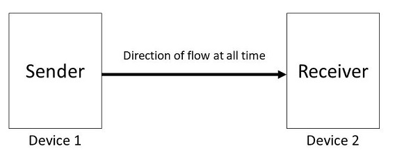
In simplex communication mode, data flows in a single direction between two devices, which means one device is exclusively a sender and the other is strictly a receiver. This setup is common in systems where only one-way information sharing is required, such as in some monitoring or data logging applications.
- Sender side: The DI pin is connected to a transmitting data line from the microcontroller and the DE pin is set high to enable data transmission. The sender’s RO and RE pins are generally not used in simplex mode.
- Receiver side: The RO pin is connected to the receiving data line of the microcontroller. The RE pin is tied low to continuously enable the receiver, allowing it to accept transmitted data. The receiver’s DI and DE pins are not utilized in simplex mode.
Example 1: Simplex Communication using the MAX485 Module & Arduino
Let us interface the MAX485 Module with Arduino and enable RS-485 Simplex Communication between two Arduino. One of the Arudino will act as a transmitter and the other will act as a receiver.
Circuit Diagram & Connection
Here is the circuit diagram for demonstrating RS-485 communication using an Arduino boards and two MAX485 modules. The setup is designed to show simplex (one-way) communication, where one Arduino acts as the sender and the other as the receiver in RS-485 network.

For the communication, connect the pins as follow:
| Pin on MAX485 | Function | Connected to Arduino Pin |
|---|---|---|
| DI (Driver Input) | Transmits data | 11 (TX of SoftwareSerial) |
| RO (Receiver Output) | Receives data | 10 (RX of SoftwareSerial) |
| DE (Driver Enable) | Enables transmission | 3 |
| RE (Receiver Enable) | Disables receiver | 2 |

Connect the A of the Sender MAX485 Module to A of the receiver MAX485 Module. Also connect the B of the Sender MAX485 Module to b of the receiver MAX485 Module. Power the module with 5V pin of Arduino.
Sender Code
In the following code, we configures the board to send random numerical data between 0 and 100 over RS-485 using a MAX485 module, where the DE and RE pins are set high to enable transmission mode.
The sent data is also displayed on the Arduino’s serial monitor.
|
1 2 3 4 5 6 7 8 9 10 11 12 13 14 15 16 17 18 19 20 21 22 23 24 25 26 27 28 29 30 31 32 33 34 35 36 37 38 |
// Sender Code #include <SoftwareSerial.h> // Define the pins for the MAX485 #define DE 3 #define RE 2 // Create a SoftwareSerial object to communicate with the MAX485 SoftwareSerial RS485Serial(10, 11); // RX, TX void setup() { // Initialize the serial communication Serial.begin(9600); RS485Serial.begin(9600); // Set the DE and RE pins as outputs pinMode(DE, OUTPUT); pinMode(RE, OUTPUT); // Set DE and RE high to enable transmission mode digitalWrite(DE, HIGH); digitalWrite(RE, HIGH); } void loop() { // Generate random data int data = random(0, 100); // Send data over RS485 RS485Serial.write(data); // Print the sent data to the serial monitor Serial.print("Data sent: "); Serial.println(data); // Wait for a while before sending the next data delay(2000); } |
Receiver Code
In the following code, we configure the Arduino board to receive data over RS-485 using a MAX485 module. Here both DE (Driver Enable) and RE (Receiver Enable) pins are set low to enable the receiving mode.
When data is received, it is read from the RS-485 network, printed to the Arduino’s serial monitor, and accompanied by a confirmation message indicating successful reception.
|
1 2 3 4 5 6 7 8 9 10 11 12 13 14 15 16 17 18 19 20 21 22 23 24 25 26 27 28 29 30 31 32 33 34 35 36 37 |
// Receiver Code #include <SoftwareSerial.h> // Define the pins for the MAX485 #define DE 3 #define RE 2 // Create a SoftwareSerial object to communicate with the MAX485 SoftwareSerial RS485Serial(10, 11); // RX, TX void setup() { // Initialize the serial communication Serial.begin(9600); RS485Serial.begin(9600); // Set the DE and RE pins as outputs pinMode(DE, OUTPUT); pinMode(RE, OUTPUT); // Set DE and RE low to enable receiving mode digitalWrite(DE, LOW); digitalWrite(RE, LOW); } void loop() { if (RS485Serial.available()) { // Read the received data int receivedData = RS485Serial.read(); // Print the received data to the serial monitor Serial.print("Data received: "); Serial.println(receivedData); // Print a successful message Serial.println("Data successfully received."); } } |
Upload both the code to sender and receiver Arduino board. Then open the Serial Monitor and set the baud rate to 9600.
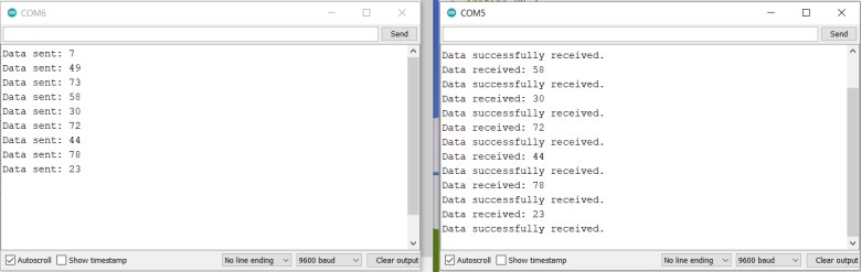
The serial monitor windows display the RS-485 communication between two Arduinos: the sender transmits random numbers, and the receiver acknowledges each received number with a confirmation message, demonstrating successful data transfer.
Example 2: Sending DHT11 Sensor Data over RS-485 using Arduino
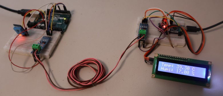
In this example, we will send the DHT11 Sensor data from transmitter and display on LCD on the receiver.
Circuit Diagram & Connection
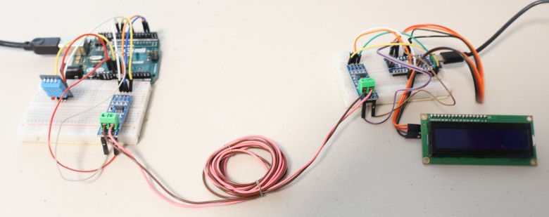
Here is the circuit diagram for connecting DHT11 Sensor to the sender and 16X2 LCD Display to the receiver.

The DHT11 sensor is connected to A0 pin of the Arduino. On the receiver side, connect the SDA & SCL pin of LCD Display to the A4 & A5 pin of Arduino.
Sender Code
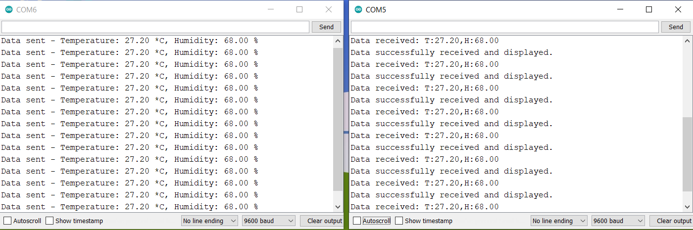
This Arduino code reads temperature and humidity data from a DHT11 sensor and transmits it over RS-485 using a MAX485 module. The data is periodically sent every 2 seconds and also displayed on the local serial monitor.
|
1 2 3 4 5 6 7 8 9 10 11 12 13 14 15 16 17 18 19 20 21 22 23 24 25 26 27 28 29 30 31 32 33 34 35 36 37 38 39 40 41 42 43 44 45 46 47 48 49 50 51 52 53 54 55 56 57 58 59 60 61 62 63 |
#include <SoftwareSerial.h> #include <DHT.h> // Define the pins for the MAX485 #define DE 3 #define RE 2 // DHT11 sensor pin and type #define DHTPIN 7 #define DHTTYPE DHT11 DHT dht(DHTPIN, DHTTYPE); // Create a SoftwareSerial object to communicate with the MAX485 SoftwareSerial RS485Serial(10, 11); // RX, TX void setup() { // Initialize the serial communication Serial.begin(9600); RS485Serial.begin(9600); // Initialize the DHT11 sensor dht.begin(); // Set the DE and RE pins as outputs pinMode(DE, OUTPUT); pinMode(RE, OUTPUT); // Set DE and RE high to enable transmission mode digitalWrite(DE, HIGH); digitalWrite(RE, HIGH); } void loop() { // Add a small delay to ensure the DHT sensor is ready delay(2000); // 2 seconds delay // Read data from DHT11 sensor float humidity = dht.readHumidity(); float temperature = dht.readTemperature(); // Check if any reads failed and exit early (to try again). if (isnan(humidity) || isnan(temperature)) { Serial.println("Failed to read from DHT sensor!"); return; } // Send temperature and humidity data over RS485 RS485Serial.print("T:"); RS485Serial.print(temperature); RS485Serial.print(",H:"); RS485Serial.println(humidity); // Print the sent data to the serial monitor Serial.print("Data sent - Temperature: "); Serial.print(temperature); Serial.print(" *C, Humidity: "); Serial.print(humidity); Serial.println(" %"); // Wait for a while before sending the next data delay(2000); } |
Receiver Code
This Arduino receiver code reads temperature and humidity data transmitted over RS-485, displays it on an LCD screen, and prints it to the serial monitor. It also indicates successful reception and display of data on the LCD.
|
1 2 3 4 5 6 7 8 9 10 11 12 13 14 15 16 17 18 19 20 21 22 23 24 25 26 27 28 29 30 31 32 33 34 35 36 37 38 39 40 41 42 43 44 45 46 47 48 49 50 51 52 53 54 55 56 57 58 59 60 61 62 63 64 65 66 67 68 69 70 |
// Receiver Code #include <Wire.h> #include <LiquidCrystal_I2C.h> #include <SoftwareSerial.h> // Define the pins for the MAX485 #define DE 3 #define RE 2 // Create a SoftwareSerial object to communicate with the MAX485 SoftwareSerial RS485Serial(10, 11); // RX, TX // Set the LCD address to 0x27 for a 16 chars and 2 line display LiquidCrystal_I2C lcd(0x27, 16, 2); void setup() { // Initialize the serial communication Serial.begin(9600); RS485Serial.begin(9600); // Initialize the LCD lcd.init(); lcd.backlight(); // Set the DE and RE pins as outputs pinMode(DE, OUTPUT); pinMode(RE, OUTPUT); // Set DE and RE low to enable receiving mode digitalWrite(DE, LOW); digitalWrite(RE, LOW); // Print a message to the LCD. lcd.setCursor(0, 0); lcd.print("Waiting for data"); } void loop() { if (RS485Serial.available()) { // Read the received data String receivedData = RS485Serial.readStringUntil('\n'); // Print the received data to the serial monitor Serial.print("Data received: "); Serial.println(receivedData); // Extract temperature and humidity from the received data int tempIndex = receivedData.indexOf("T:"); int humIndex = receivedData.indexOf("H:"); if (tempIndex >= 0 && humIndex >= 0) { float temperature = receivedData.substring(tempIndex + 2, receivedData.indexOf(',', tempIndex)).toFloat(); float humidity = receivedData.substring(humIndex + 2).toFloat(); // Display the temperature and humidity on the LCD lcd.clear(); lcd.setCursor(0, 0); lcd.print("Temp: "); lcd.print(temperature); lcd.print(" C"); lcd.setCursor(0, 1); lcd.print("Humi: "); lcd.print(humidity); lcd.print(" %"); // Print a successful message Serial.println("Data successfully received and displayed."); } } } |
After uploading the code to the Arduino board, the LCD Display will the following message first.
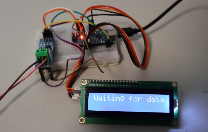
After that, the LCD will display temperature and humidity. You may heat the DHT11 sensor and observe the change in temperature and humidity.
You may open your Serial Monitor for both the Arduino Boards. The Serial Monitor will show the transmitted and received data.
This is how you can use RS-485 Simplex Communication with Arduino using the MAX485 Module.

")


1 Comment
Very nice write up. Thanks!
But there is something I don’t understand.
Is there an error in the wiring diagrams?
For both RX an TX the sketch sets RX=DP10 and TX=DP11.
In the wiring diagrams:
For the TX side : DP10 (RX) is connected to RO
DP11(TX) is connected to DI
For the RX side: DP10(RX) is connected to DI
DP11(TX) is connected to RO
Maybe I misunderstand things…
Thanks for any comment , if you see this. Jim : )