

Overview
In this project, we will be interfacing the 74HC595 Shift Register with the Raspberry Pi Pico using MicroPython. We will use the 74HC595 along with multiple LEDs to create two example projects: LED Chaser and LED Larson Scanner.
The Raspberry Pi Pico provides a reasonable number of I/O pins, making it great for controlling various components like LEDs, sensors, and servos. However, as your project grows, you might run out of pins to use. A shift register like the 74HC595 offers an efficient solution by expanding the number of available output pins. This IC allows control of up to 8 output pins using just 3 GPIO pins on the Pico. Moreover, by daisy-chaining multiple 74HC595 registers, you can control an even larger number of outputs.
This tutorial demonstrates how to connect the 74HC595 shift register to a Raspberry Pi Pico using MicroPython. We will implement two engaging projects: LED Chaser and LED Larson Scanner. These projects show how useful the 74HC595 is, allowing you to create cool light patterns and smooth LED effects while using only a few GPIO pins.
Components Needed
- Raspberry Pi Pico Board
- 74HC595 Shift Register
- 8 LEDs
- 8 Resistors (220Ω recommended)
- Breadboard
- Jumper Wires
74HC595 Shift Register
The 74HC595 is an 8-bit serial-in, parallel-out shift register. It is a popular IC used for expanding the number of output pins on a microcontroller. By using a shift register like the 74HC595, you can control multiple outputs, such as LEDs, with just a few pins from your microcontroller. This makes it ideal for projects where the microcontroller’s pins are limited but multiple outputs are needed.
The 74HC595 has 8 output pins (Q0–Q7) that can be controlled using only three control pins from a microcontroller. Additionally, multiple 74HC595 ICs can be daisy-chained together to control even more outputs while still using the same three control pins. Refer to 74HC595 Datasheet for more information.
How Does the 74HC595 Work?
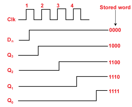
The 74HC595 works by receiving data serially (one bit at a time) and then outputting it parallelly (to 8 output pins) after the data is latched. It uses a process called bit-shifting to move the data into its internal register. Here’s the basic process:
- Data Loading:
- The microcontroller sends a serial data stream (0s and 1s) to the
SER(Data) pin of the 74HC595. - Each bit of data is shifted into the shift register on the rising edge of the
SRCLK(Shift Register Clock) pin.
- The microcontroller sends a serial data stream (0s and 1s) to the
- Data Latching:
- Once all 8 bits of data are sent, the
RCLK(Register Clock, also called Latch) pin is triggered. This transfers the data from the shift register to the output register, making it appear on the output pins (Q0–Q7).
- Once all 8 bits of data are sent, the
- Output Control:
- The
OE(Output Enable) pin allows you to control whether the outputs are active. By default,OEis tied to the ground to keep the outputs active.
- The
By repeating this process, the 74HC595 can control its outputs or daisy chain with additional ICs for more outputs.
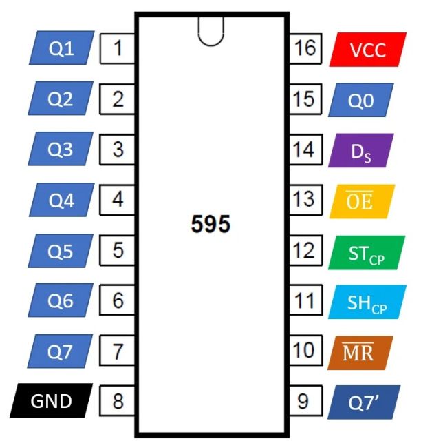
74HC595 Pinout and Their Functions
The 74HC595 has 16 pins, and their functions are as follows:
| Pin | Name | Function |
|---|---|---|
| 1 | Q1 | Output pin 1 (parallel output) |
| 2 | Q2 | Output pin 2 (parallel output) |
| 3 | Q3 | Output pin 3 (parallel output) |
| 4 | Q4 | Output pin 4 (parallel output) |
| 5 | Q5 | Output pin 5 (parallel output) |
| 6 | Q6 | Output pin 6 (parallel output) |
| 7 | Q7 | Output pin 7 (parallel output) |
| 8 | GND | Ground |
| 9 | Q7’ | Serial out (used for daisy-chaining another 74HC595 IC) |
| 10 | MR | Master Reset (active low, used to reset all outputs to 0) |
| 11 | SRCLK | Shift Register Clock (triggers the shift of the bits in the shift register) |
| 12 | RCLK | Register Clock (latches the shifted data to the output pins) |
| 13 | OE | Output Enable (active low, enables or disables the outputs) |
| 14 | SER | Serial Data Input (receives serial data from the microcontroller) |
| 15 | Q0 | Output pin 0 (parallel output) |
| 16 | VCC | Supply voltage (2V to 6V) |
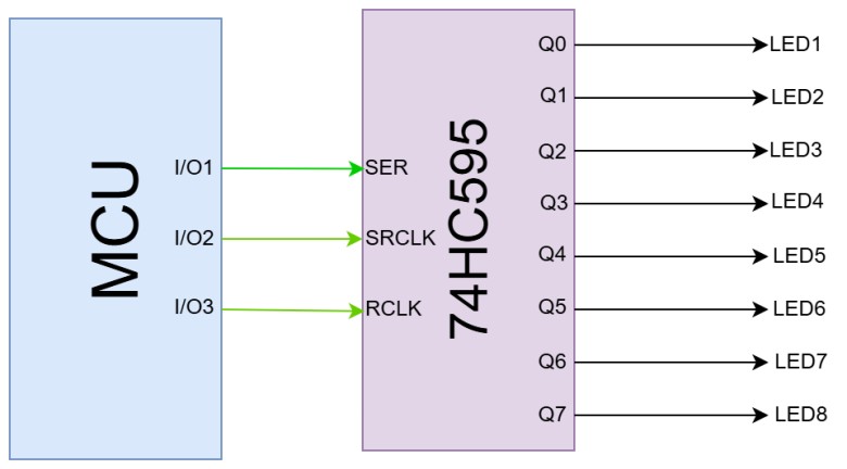
How to Use the 74HC595 with a Microcontroller
Using the 74HC595 with a microcontroller, such as an Raspberry Pi Pico, is straightforward. The microcontroller controls the SER, SRCLK, and RCLK pins of the 74HC595 to shift and latch the data.
- Basic Connections:
- Connect the
SERpin of the 74HC595 to a data output pin of the microcontroller. - Connect the
SRCLKpin to a clock output pin of the microcontroller. - Connect the
RCLKpin to a latch output pin of the microcontroller. - Connect the
OEpin to GND (or a PWM pin if brightness control is needed). - Connect the
MRpin to VCC (to disable reset functionality). - Connect LEDs or other devices to the output pins (Q0–Q7).
- Data Transmission:
- Send a byte of data (8 bits) to the
SERpin one bit at a time. - Pulse the
SRCLKpin for each bit to shift it into the register. - After all 8 bits are shifted, pulse the
RCLKpin to latch the data to the outputs.
- Controlling Outputs:
- The data sent determines which outputs (Q0–Q7) are HIGH or LOW. For example:
- Sending
0b00000001lights up Q0. - Sending
0b10000000lights up Q7.
- Sending
Daisy-Chaining Multiple 74HC595 ICs
To control more than 8 outputs, you can daisy-chain multiple 74HC595 ICs. The Q7’ pin of one IC is connected to the SER pin of the next IC. The SRCLK and RCLK pins of all ICs are connected in parallel to the microcontroller.
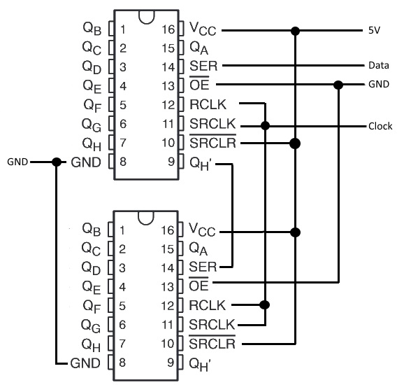
This setup allows you to shift data through the chain of ICs, enabling control of a virtually unlimited number of outputs.
Applications of the 74HC595
- LED Displays: Control multiple LEDs or 7-segment displays.
- Matrix Keypads: Read inputs from a keypad using fewer pins.
- Motor Control: Drive multiple relays or motors.
- Digital Indicators: Control binary or decimal indicators.
By combining the 74HC595 with a microcontroller, you can efficiently manage projects with multiple outputs while conserving precious I/O pins.
Hardware Connection between 74HC595 and Raspberry Pi Pico
Since we are going to use 74HC595 with an Raspberry Pi Pico and many LEDs, we will connect the components on a breadboard as per the following circuit diagram.
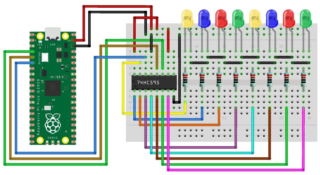
Here is the connection detail:
- 74HC595 to Raspberry Pi Pico:
- Pin 11 (SRCLK) to GP2 (clockPin)
- Pin 12 (RCLK) to GP3 (latchPin)
- Pin 14 (SER) to GP4 (dataPin)
- Pin 8 (GND) to GND
- Pin 16 (Vcc) to 3.3V
- Pin 10 (SRCLR) to 3.3V
- Pin 13 (OE) to GND
- LEDs to 74HC595:
- Connect each LED anode to Q0-Q7 (pins 15, 1, 2, 3, 4, 5, 6, 7) through a resistor.
- Connect all LED cathodes to the GND rail.
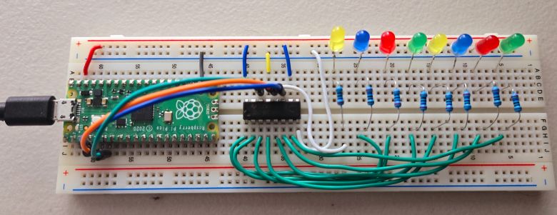
There will be so many connections, so it requires many jumper wires and a good breadboard. As shown above, properly connect the components on the breadboard.
Example 1: LED Chaser using 74HC595 & Raspberry Pi Pico
An LED chaser creates a fun visual effect by lighting up LEDs one after another in a sequence, giving the appearance of a moving or chasing light. You can customize the effect by changing the speed at which the LEDs light up or even reversing the direction to make the light move back and forth, adding more variety and dynamic motion. This effect is simple to create and looks great in decorative or interactive projects.
Here is the MicroPython Code that can create LED Chaser effect when 74HC595 is used with 8 LEDs and Raspberry Pi Pico.
|
1 2 3 4 5 6 7 8 9 10 11 12 13 14 15 16 17 18 19 20 21 22 23 |
from machine import Pin from time import sleep latchPin = Pin(3, Pin.OUT) clockPin = Pin(2, Pin.OUT) dataPin = Pin(4, Pin.OUT) def update_shift_register(value): latchPin.value(0) for i in range(8): clockPin.value(0) dataPin.value((value >> (7 - i)) & 1) clockPin.value(1) latchPin.value(1) def led_chase(): for i in range(8): leds = 1 << i update_shift_register(leds) sleep(0.1) # Adjust delay for speed while True: led_chase() |
This code controls a shift register connected to a Raspberry Pi Pico, creating an LED chaser effect. It sequentially lights up each LED one by one by shifting data through the shift register, with a small delay to adjust the speed of the chase. The update_shift_register() function sends data to the shift register, and the led_chase() function lights up each LED in sequence.
Run the MicroPython Code and you will see the following LED Chaser effect.
Example 2: LED Larson Scanner using 74HC595 & Raspberry Pi Pico
The LED Larson Scanner creates a cool effect inspired by the Knight Rider light bar, where LEDs light up one after another in a back-and-forth motion. Unlike simple on-off transitions, each LED gradually fades in and out, making the movement smoother and more fluid. This creates an eye-catching and visually appealing scanning effect that’s great for decorative or interactive projects. You can also adjust the speed or brightness to customize the look.
Here is the MicroPython Code that can create LED Larson Scanner effect when 74HC595 is used with 8 LEDs and Raspberry Pi Pico.
|
1 2 3 4 5 6 7 8 9 10 11 12 13 14 15 16 17 18 19 20 21 22 23 24 25 26 27 28 29 30 31 32 33 34 |
from machine import Pin, PWM from time import sleep latchPin = Pin(3, Pin.OUT) clockPin = Pin(2, Pin.OUT) dataPin = Pin(4, Pin.OUT) def update_shift_register(value): latchPin.value(0) for i in range(8): clockPin.value(0) dataPin.value((value >> (7 - i)) & 1) clockPin.value(1) latchPin.value(1) def fade_led(led_index, direction): for brightness in range(0, 256, 5): pwm_value = 255 - brightness if direction > 0 else brightness PWM(latchPin, freq=1000, duty_u16=pwm_value * 256) leds = (1 << led_index) if direction > 0 else 0 update_shift_register(leds) sleep(0.005) # Adjust delay for fading speed while True: # Sweep from left to right for i in range(8): fade_led(i, 1) sleep(0.1) # Adjust delay for speed fade_led(i, -1) # Sweep from right to left for i in range(7, -1, -1): fade_led(i, 1) sleep(0.1) # Adjust delay for speed fade_led(i, -1) |
This code creates a sweeping LED effect using a shift register and PWM control. Each LED gradually fades in and out as the light moves back and forth across the sequence, creating a smooth and dynamic visual effect. The fade_led() function handles the fading for each LED, while the update_shift_register() function sends data to the shift register to control which LED is lit.
Run the MicroPython Code and you will see the following LED Larson Scanner effect.


1 Comment
I think (as in I am 99% certain) that there is an error in the schematic diagram and in the text which reads “To control more than 8 outputs, you can daisy-chain multiple 74HC595 ICs. The Q7’ pin of one IC is connected to the SER pin of the next IC. The SRCLK and RCLK pins of all ICs are connected in parallel to the microcontroller.”
In fact the SRCLK pins should all be connected, and the RCLK pins should all be connected….BUT the SRCLKs and RCLKs should NOT be connected together! The schematic diagram shows them all tied together so this is also wrong. (In fact the text is a bit ambiguous, but the diagram confirms the error.)