

Overview
In this project, we will be interfacing 74HC595 Shift Register with Arduino. We will use 74HC595 with Arduino and multiple LEDs to create few example projects.
The Arduino provides a good number of I/O pins, making it ideal for controlling various components like LEDs, sensors, and servos. However, as your project grows, you might run out of pins to use. A shift register like the 74HC595 offers an elegant solution by expanding the number of I/O pins available. This IC allows control of up to 8 output pins using just 3 input pins, and by daisy-chaining multiple 74HC595 registers, you can control an even larger number of outputs. This technique, known as bit-shifting, is powerful for managing LEDs, displays, or any scenario requiring numerous output pins.
This tutorial shows how to connect the 74HC595 shift register to an Arduino and use it in five fun projects: LED Chaser, Heartbeat LED Effect, PWM Brightness Control, LED Wave Effect, and LED Larson Scanner. These projects demonstrate how flexible the 74HC595 is, letting you create cool light patterns and smoothly adjust LED brightness using PWM.
Components Needed
- Arduino Board
- 74HC595 Shift Register
- 8 LEDs
- 8 Resistors (220Ω recommended)
- Breadboard
- Jumper Wires
74HC595 Shift Register
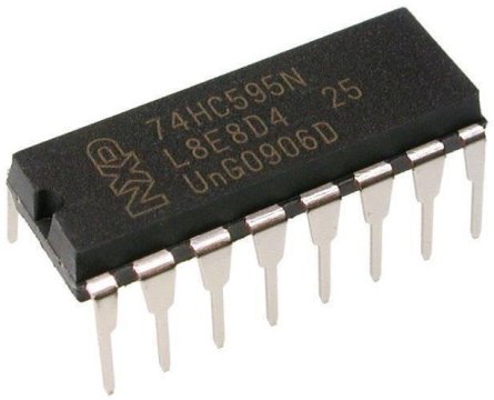
The 74HC595 is an 8-bit serial-in, parallel-out shift register. It is a popular IC used for expanding the number of output pins on a microcontroller. By using a shift register like the 74HC595, you can control multiple outputs, such as LEDs, with just a few pins from your microcontroller. This makes it ideal for projects where the microcontroller’s pins are limited but multiple outputs are needed.
The 74HC595 has 8 output pins (Q0–Q7) that can be controlled using only three control pins from a microcontroller. Additionally, multiple 74HC595 ICs can be daisy-chained together to control even more outputs while still using the same three control pins. Refer to 74HC595 Datasheet for more information.
How Does the 74HC595 Work?
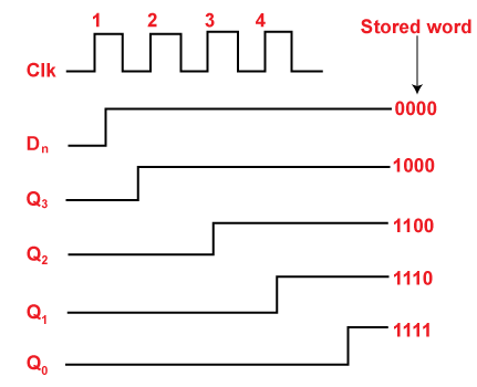
The 74HC595 works by receiving data serially (one bit at a time) and then outputting it parallelly (to 8 output pins) after the data is latched. It uses a process called bit-shifting to move the data into its internal register. Here’s the basic process:
- Data Loading:
- The microcontroller sends a serial data stream (0s and 1s) to the
SER(Data) pin of the 74HC595. - Each bit of data is shifted into the shift register on the rising edge of the
SRCLK(Shift Register Clock) pin.
- The microcontroller sends a serial data stream (0s and 1s) to the
- Data Latching:
- Once all 8 bits of data are sent, the
RCLK(Register Clock, also called Latch) pin is triggered. This transfers the data from the shift register to the output register, making it appear on the output pins (Q0–Q7).
- Once all 8 bits of data are sent, the
- Output Control:
- The
OE(Output Enable) pin allows you to control whether the outputs are active. By default,OEis tied to the ground to keep the outputs active.
- The
By repeating this process, the 74HC595 can control its outputs or daisy chain with additional ICs for more outputs.
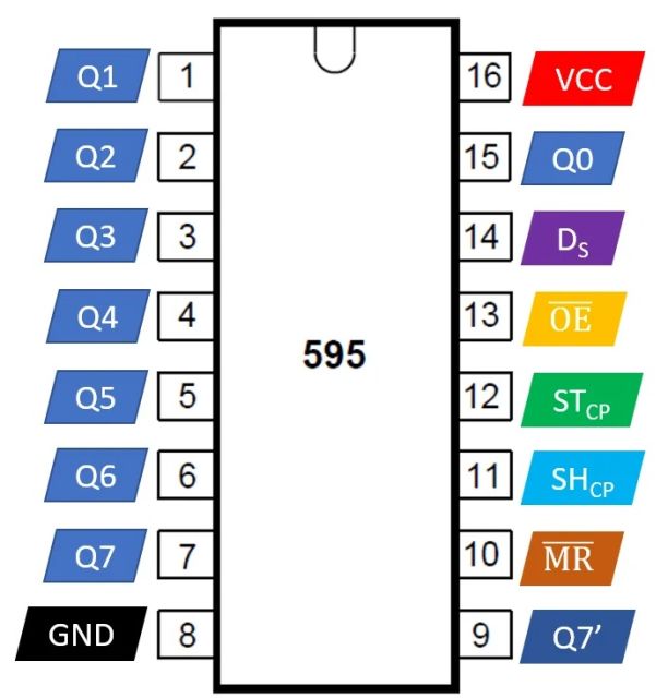
74HC595 Pinout and Their Functions
The 74HC595 has 16 pins, and their functions are as follows:
| Pin | Name | Function |
|---|---|---|
| 1 | Q1 | Output pin 1 (parallel output) |
| 2 | Q2 | Output pin 2 (parallel output) |
| 3 | Q3 | Output pin 3 (parallel output) |
| 4 | Q4 | Output pin 4 (parallel output) |
| 5 | Q5 | Output pin 5 (parallel output) |
| 6 | Q6 | Output pin 6 (parallel output) |
| 7 | Q7 | Output pin 7 (parallel output) |
| 8 | GND | Ground |
| 9 | Q7’ | Serial out (used for daisy-chaining another 74HC595 IC) |
| 10 | MR | Master Reset (active low, used to reset all outputs to 0) |
| 11 | SRCLK | Shift Register Clock (triggers the shift of the bits in the shift register) |
| 12 | RCLK | Register Clock (latches the shifted data to the output pins) |
| 13 | OE | Output Enable (active low, enables or disables the outputs) |
| 14 | SER | Serial Data Input (receives serial data from the microcontroller) |
| 15 | Q0 | Output pin 0 (parallel output) |
| 16 | VCC | Supply voltage (2V to 6V) |
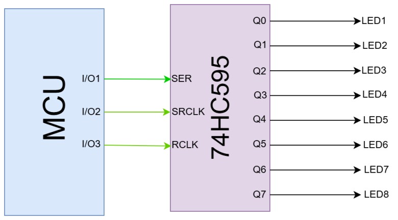
How to Use the 74HC595 with a Microcontroller
Using the 74HC595 with a microcontroller, such as an Arduino, is straightforward. The microcontroller controls the SER, SRCLK, and RCLK pins of the 74HC595 to shift and latch the data.
- Basic Connections:
- Connect the
SERpin of the 74HC595 to a data output pin of the microcontroller. - Connect the
SRCLKpin to a clock output pin of the microcontroller. - Connect the
RCLKpin to a latch output pin of the microcontroller. - Connect the
OEpin to GND (or a PWM pin if brightness control is needed). - Connect the
MRpin to VCC (to disable reset functionality). - Connect LEDs or other devices to the output pins (Q0–Q7).
- Data Transmission:
- Send a byte of data (8 bits) to the
SERpin one bit at a time. - Pulse the
SRCLKpin for each bit to shift it into the register. - After all 8 bits are shifted, pulse the
RCLKpin to latch the data to the outputs.
- Controlling Outputs:
- The data sent determines which outputs (Q0–Q7) are HIGH or LOW. For example:
- Sending
0b00000001lights up Q0. - Sending
0b10000000lights up Q7.
- Sending
Daisy-Chaining Multiple 74HC595 ICs
To control more than 8 outputs, you can daisy-chain multiple 74HC595 ICs. The Q7’ pin of one IC is connected to the SER pin of the next IC. The SRCLK and RCLK pins of all ICs are connected in parallel to the microcontroller.
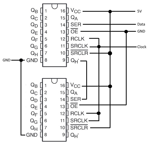
This setup allows you to shift data through the chain of ICs, enabling control of a virtually unlimited number of outputs.
Applications of the 74HC595
- LED Displays: Control multiple LEDs or 7-segment displays.
- Matrix Keypads: Read inputs from a keypad using fewer pins.
- Motor Control: Drive multiple relays or motors.
- Digital Indicators: Control binary or decimal indicators.
By combining the 74HC595 with a microcontroller, you can efficiently manage projects with multiple outputs while conserving precious I/O pins.
Hardware Connection between 74HC595 and Arduino
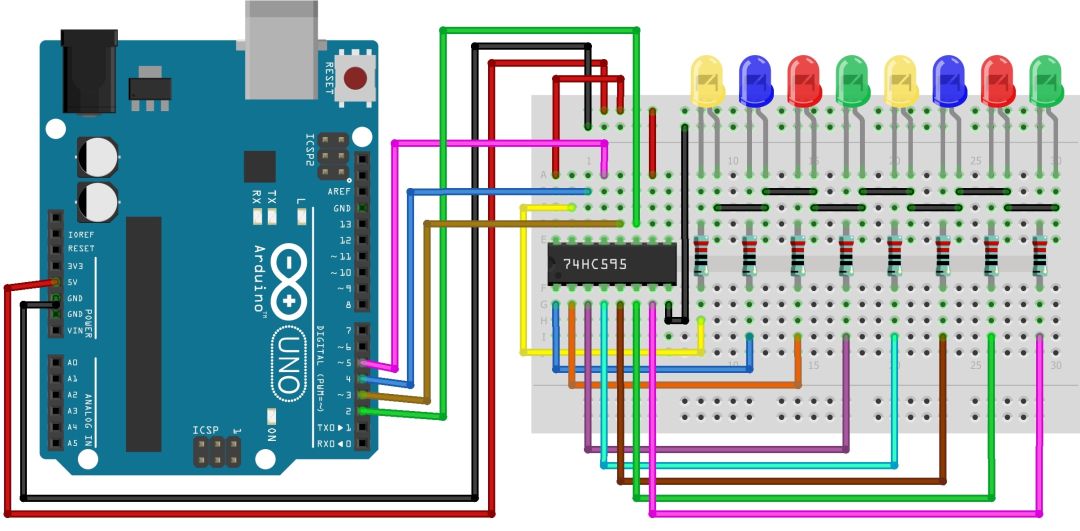
Since we are going to use 74HC595 with an Arduino and many LEDs, we will connect the components on a breadboard as per the following circuit diagram.

Here is the connection detail:
- 74HC595 to Arduino:
- Pin 11 (SRCLK) to Arduino pin 2 (clockPin)
- Pin 12 (RCLK) to Arduino pin 3 (latchPin)
- Pin 14 (SER) to Arduino pin 4 (dataPin)
- Pin 8 (GND) to Arduino GND
- Pin 16 (Vcc) to Arduino 5V
- Pin 10 (SRCLR) to Arduino 5V
- Pin 13 (OE) to Arduino GND
- LEDs to 74HC595:
- Connect each LED anode to Q0-Q7 (pins 15, 1, 2, 3, 4, 5, 6, 7) through a resistor.
- Connect all LED cathodes to the GND rail.
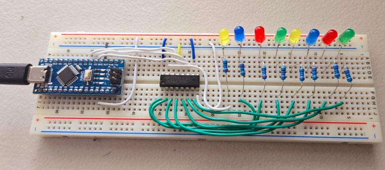
There will be so many connections, so it requires many jumper wires and a good breadboard. As shown above, properly connect the components on the breadboard. I used an Arduino Nano instead of an Arduino UNO Board.
Project 1: LED Chaser using 74HC595 & Arduino
An LED chaser creates a visual effect where LEDs light up one by one in a sequential pattern, resembling a chasing motion. Variations can include adjusting the speed of the sequence or reversing the direction of the chase for added dynamics.
We can use the following code with Arduino to develop LED Chaser circuit using 74HC595.
|
1 2 3 4 5 6 7 8 9 10 11 12 13 14 15 16 17 18 19 20 21 22 23 24 25 26 27 28 29 30 31 32 |
int latchPin = 3; // Latch pin of 74HC595 is connected to Digital pin 3 int clockPin = 2; // Clock pin of 74HC595 is connected to Digital pin 2 int dataPin = 4; // Data pin of 74HC595 is connected to Digital pin 4 void setup() { // Set all the pins as output pinMode(latchPin, OUTPUT); pinMode(clockPin, OUTPUT); pinMode(dataPin, OUTPUT); } void loop() { for (int i = 0; i < 8; i++) { // Move the single high bit (1) from left to right int value = 1 << i; updateShiftRegister(value); delay(100); // Adjust delay for speed } for (int i = 6; i > 0; i--) { // Move the single high bit (1) from right to left int value = 1 << i; updateShiftRegister(value); delay(200); // Adjust delay for speed } } void updateShiftRegister(int value) { // Begin the shifting process digitalWrite(latchPin, LOW); shiftOut(dataPin, clockPin, MSBFIRST, value); digitalWrite(latchPin, HIGH); } |
Upload the code to the Arduino Board and then the LED Chaser circuit starts working.
Project 2: Heartbeat LED Effect using 74HC595 & Arduino
The heartbeat LED effect simulates a pulsating pattern where LEDs brighten and dim rhythmically, resembling the natural heartbeat. The effect typically involves two pulses in quick succession followed by a pause, creating a realistic heartbeat rhythm.
We can use the following code with Arduino to develop Heartbeat LED Effect circuit using 74HC595.
|
1 2 3 4 5 6 7 8 9 10 11 12 13 14 15 16 17 18 19 20 21 22 23 24 25 26 27 28 29 30 31 32 33 34 35 36 37 38 39 40 41 42 43 44 45 46 47 48 |
int latchPin = 3; // Latch pin of 74HC595 is connected to Digital pin 3 int clockPin = 2; // Clock pin of 74HC595 is connected to Digital pin 2 int dataPin = 4; // Data pin of 74HC595 is connected to Digital pin 4 void setup() { // Set all the pins as output pinMode(latchPin, OUTPUT); pinMode(clockPin, OUTPUT); pinMode(dataPin, OUTPUT); } void loop() { // Create heartbeat effect heartbeatEffect(); } void heartbeatEffect() { int delayTime = 50; // Adjust delay for speed of heartbeat // First pulse for (int i = 0; i < 8; i++) { updateShiftRegister(1 << i); delay(delayTime); } for (int i = 6; i >= 0; i--) { updateShiftRegister(1 << i); delay(delayTime); } // Short pause between pulses delay(200); // Second pulse (shorter and faster) for (int i = 0; i < 8; i++) { updateShiftRegister(1 << i); delay(delayTime / 2); } for (int i = 6; i >= 0; i--) { updateShiftRegister(1 << i); delay(delayTime / 2); } // Longer pause before next heartbeat delay(1000); } void updateShiftRegister(int value) { // Begin the shifting process digitalWrite(latchPin, LOW); shiftOut(dataPin, clockPin, MSBFIRST, value); digitalWrite(latchPin, HIGH); } |
As soon as you upload the code to the Arduino Board, Heartbeat LED Effect project starts working.
Project 3: PWM Brightness Control using 74HC595 & Arduino
This project uses Pulse Width Modulation (PWM) to control the brightness of LEDs by manipulating the Output Enable (OE) pin of the 74HC595 IC. By adjusting the PWM duty cycle, the LEDs’ brightness can be varied dynamically, creating smooth dimming and lighting effects.
Here is the schematic for this project. Connect the OE pin of 74HC595 with digital pin 5 of the Arduino board.
Here is the code for controlling the brightness of LED using the PWM.
|
1 2 3 4 5 6 7 8 9 10 11 12 13 14 15 16 17 18 19 20 21 22 23 24 25 26 27 28 29 30 31 32 33 34 35 36 37 38 39 40 41 42 43 44 45 46 47 48 49 50 51 52 53 54 55 56 57 58 59 |
int latchPin = 3; // Latch pin of 74HC595 is connected to Digital pin 3 int clockPin = 2; // Clock pin of 74HC595 is connected to Digital pin 2 int dataPin = 4; // Data pin of 74HC595 is connected to Digital pin 4 int outputEnablePin = 5; // OE pin of 74HC595 is connected to PWM pin 5 byte leds = 0; // Variable to hold the pattern of which LEDs are currently turned on or off /* * setup() - this function runs once when you turn your Arduino on * We initialize the serial connection with the computer */ void setup() { // Set all the pins of 74HC595 as OUTPUT pinMode(latchPin, OUTPUT); pinMode(dataPin, OUTPUT); pinMode(clockPin, OUTPUT); pinMode(outputEnablePin, OUTPUT); } /* * loop() - this function runs over and over again */ void loop() { setBrightness(255); leds = 0; // Initially turns all the LEDs off, by giving the variable 'leds' the value 0 updateShiftRegister(); delay(500); for (int i = 0; i < 8; i++) // Turn all the LEDs ON one by one. { bitSet(leds, i); // Set the bit that controls that LED in the variable 'leds' updateShiftRegister(); delay(500); } for (byte b = 255; b > 0; b--) // Gradually fade all the LEDs back to off { setBrightness(b); delay(20); // Adjusted delay for faster dimming } } /* * updateShiftRegister() - This function sets the latchPin to low, then calls the Arduino function 'shiftOut' to shift out contents of variable 'leds' in the shift register before putting the 'latchPin' high again. */ void updateShiftRegister() { digitalWrite(latchPin, LOW); shiftOut(dataPin, clockPin, LSBFIRST, leds); digitalWrite(latchPin, HIGH); } /* * setBrightness() - Generates PWM signal and writes it to OE pin. */ void setBrightness(byte brightness) // 0 to 255 { analogWrite(outputEnablePin, 255-brightness); } |
Upload the code and you will the dimming effect of LED due to PWM signal.
Project 4: LED Wave Effect using 74HC595 & Arduino
The LED wave effect creates a dynamic pattern where LEDs light up in a sequence that mimics a sine wave. The brightness of each LED gradually increases and decreases to form a smooth wave-like motion. The speed and amplitude of the wave can be adjusted to achieve different visual effects.
Here is the Arduino code that can mimics a sine wave pattern which is also called LED Wave Effect.
|
1 2 3 4 5 6 7 8 9 10 11 12 13 14 15 16 17 18 19 20 21 22 23 24 25 26 27 28 29 30 31 32 33 34 35 36 37 38 39 40 41 42 |
int latchPin = 3; // Latch pin of 74HC595 is connected to Digital pin 3 int clockPin = 2; // Clock pin of 74HC595 is connected to Digital pin 2 int dataPin = 4; // Data pin of 74HC595 is connected to Digital pin 4 int outputEnablePin = 5; // OE pin of 74HC595 is connected to PWM pin 5 void setup() { // Set all the pins as output pinMode(latchPin, OUTPUT); pinMode(clockPin, OUTPUT); pinMode(dataPin, OUTPUT); pinMode(outputEnablePin, OUTPUT); analogWrite(outputEnablePin, 0); // Disable output initially } void loop() { for (int i = 0; i < 360; i += 5) { // Iterate through a sine wave float rad = degreesToRadians(i); byte value = 127 + 127 * sin(rad); setWavePattern(value); delay(30); // Adjust delay for speed of wave } } void setWavePattern(byte brightness) { byte wavePattern = 0; for (int i = 0; i < 8; i++) { if (brightness > (i * 32)) { wavePattern |= (1 << i); } } updateShiftRegister(wavePattern); } void updateShiftRegister(byte value) { digitalWrite(latchPin, LOW); shiftOut(dataPin, clockPin, MSBFIRST, value); digitalWrite(latchPin, HIGH); } float degreesToRadians(int degree) { return degree * (PI / 180.0); } |
Upload the code and you will see the LED Wave effect.
Project 5: LED Larson Scanner using 74HC595 & Arduino
The LED Larson Scanner creates a dynamic effect similar to the Knight Rider light bar but with smoother transitions between LEDs. Each LED fades in and out as the light moves back and forth across the sequence, creating a fluid and visually appealing scanning motion.
Here is the code for LED Larson Scanner Effect.
|
1 2 3 4 5 6 7 8 9 10 11 12 13 14 15 16 17 18 19 20 21 22 23 24 25 26 27 28 29 30 31 32 33 34 35 36 37 38 39 40 41 42 43 |
int latchPin = 3; // Latch pin of 74HC595 is connected to Digital pin 3 int clockPin = 2; // Clock pin of 74HC595 is connected to Digital pin 2 int dataPin = 4; // Data pin of 74HC595 is connected to Digital pin 4 int outputEnablePin = 5; // OE pin of 74HC595 is connected to PWM pin 5 void setup() { // Set all the pins as output pinMode(latchPin, OUTPUT); pinMode(clockPin, OUTPUT); pinMode(dataPin, OUTPUT); pinMode(outputEnablePin, OUTPUT); analogWrite(outputEnablePin, 0); // Disable output initially } void loop() { // Sweep from left to right for (int i = 0; i < 8; i++) { fadeLED(i, 1); delay(100); // Adjust delay for speed fadeLED(i, -1); } // Sweep from right to left for (int i = 7; i >= 0; i--) { fadeLED(i, 1); delay(100); // Adjust delay for speed fadeLED(i, -1); } } void fadeLED(int ledIndex, int direction) { for (int brightness = 0; brightness <= 255; brightness += 5) { analogWrite(outputEnablePin, 255 - brightness); byte leds = direction > 0 ? (1 << ledIndex) : 0; updateShiftRegister(leds); delay(5); // Adjust delay for fading speed } } void updateShiftRegister(byte value) { digitalWrite(latchPin, LOW); shiftOut(dataPin, clockPin, MSBFIRST, value); digitalWrite(latchPin, HIGH); } |
Upload the code and you will see the LED Larson Scanner effect.
We can also write a MicroPython Code to use Shift Register 74HC595 with Raspberry Pi Pico to run various LED related projects.

")


1 Comment
In Daisy-Chaining’s Schematic, you forgot the LATCH LINE.
You’ve connnected both RCLK and SRCLK together to CLOCK LINE, but that’s wrong.
So, all SRCLK from both registers go to CLOCK LINE, and RCLK to LATCH LINE
Please update that picture!!!!!!!!!