

Overview
In this IoT project, I will show you how to make Home Automation project with ESP32 and KME Smart IoT Platform. The project doesn’t require any coding all the configuration on only done via KME Smart dashboard. By sending on/off command from KME Smart App, we can control 4 relays via ESP32 network.
Previously, we developed a Home Automation project based on the ESP32 platform, utilizing platforms such as Blynk, AWS IoT Core and Arduino IoT Cloud. To enhance portability and ease of use, a custom PCB is designed specifically for this project. Since, it does not require any coding, the method to configure the device require multiple dashboard setup and steps which we will see in the guide
Once the ESP32 connects to WiFi, it automatically links up with the KME Smart IoT Platform. This connection gives you a simple, centralized way to manage and remotely control your home devices through 4 relays. The setup is self-contained, reducing the need for other IoT apps and fits smoothly into your home automation system, making everything more convenient and functional.
Bill of Materials
For this project, we will need the following components. The component list, footprint, and quantity are given below.
| S.N. | Component | Designator | Footprint | Quantity |
|---|---|---|---|---|
| 1 | Capacitor 100nf | C1, C3, C6, C7, C8, C9, C10, C11 | CAP_0805 | 8 |
| 2 | Capacitor 10uf | C2, C4, C5 | CAP_0805 | 3 |
| 3 | Capacitor 220uF, 25V | C12 | FP-RAD-TH-D_10_0_5-L_16_1-MFG | 1 |
| 4 | Diode 1N4007 | D1, D2, D3, D4 | DIOM5027X262N | 4 |
| 5 | SP4322-01ETG | D5 | SP432201ETG | 1 |
| 6 | Optocoupler PC817C | IC1, IC3, IC4, IC5 | DIP762W60P254L458H450Q4N | 4 |
| 7 | ESP32 WROOM-32 | IC2 | ESP32WROOM3216MB | 1 |
| 8 | 2-Pin Terminal Block | J1 | 1 | |
| 9 | 3-Pin Terminal Block | J2, J3, J4, J5 | 4 | |
| 10 | Relay SRD-05VDC-SL-C | K1, K2, K3, K4 | SRD | 4 |
| 11 | LED Red | LED1, LED2, LED3, LED4, LED5 | LEDC2012X80N | 5 |
| 12 | Male Header 6 Pin | P1 | HDR1X6 | 1 |
| 13 | HLK-10M05 | PS1 | HLK10M05 | 1 |
| 14 | Transistor BC847B | Q1, Q2, Q3, Q4, Q5, Q6 | BC847B215 | 6 |
| 15 | Resistor 220R | R1, R3, R9, R11, R14, R16, R17, R19 | 805 | 8 |
| 16 | DNP | R2, R10, R15, R18 | 805 | 4 |
| 17 | Resistor 12K | R4, R12, R13 | 805 | 3 |
| 18 | Resistor 1K | R5, R7, R8, R24 | 805 | 4 |
| 19 | Resistor 470R | R6 | 805 | 1 |
| 20 | Resistor 10K | R20, R21, R22, R23 | 805 | 4 |
| 21 | Push Button Switch | S1, S2, S3, S4 | B3W1020 | 4 |
| 22 | Manual Switch (Optional) | SW1, SW2, SW3, SW4 | HDR1X2 | 4 |
| 23 | HT7333 3.3V Voltage Regulator | U1 | IC_HT7333 | 1 |
Circuit Diagram & Hardware Design
Let us take a look at the Schematic of ESP32 Automation System using KME Smart IoT platform. The schematic is designed using the Altium Designer Software.
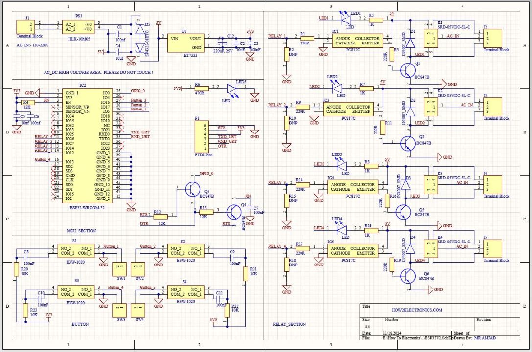
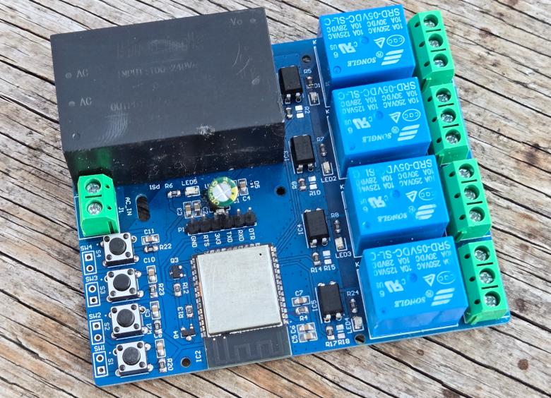
We used SMD resistors, capacitors, and LED with the 0805 package. To convert 220V AC to 5V DC, we used an AC-to-DC Converter from Hi-Link. For providing power to ESP32 raw chip and other peripherals, a low-power LDO HT7333 IC was used. To separate the high-power line from the 3.3V circuit PC817 optocoupler IC is used. The LED5 in the circuit is used to indicate power.

Similarly the LED1, LED2, LED3 & LED4 is used to represent Relay1, Relay2, Relay3 & Relay4 output respectively. The LED5 is a power indication LED. The 4 Relays are connected to ESP32 via GPIO Pins 12, 14, 27, 26. The push buttons SW1, SW2, SW3, and SW4 are used in the manual controlling of Relays. They are connected to GPIO Pins 5, 17, 13, 16. You may attach a manual switch there and program the controller to control the circuit.
You can connect 4 home appliannces using the Relay connections at 3 Pin Terminal J2, J3. J4, J5. The 2 Pin Terminal J1 is used to supply AC Power directly to the Circuit. A Capacitor C12 of 220uF, 25V is connected to PCB stop voltage fluctuations.

To program the ESP32 raw chip, the FTDI pin is provided. We can connect an FTDI Module (USB-to-TTL Converter) to program the ESP32 Chip directly.
Project PCB Gerber File & PCB Ordering Online
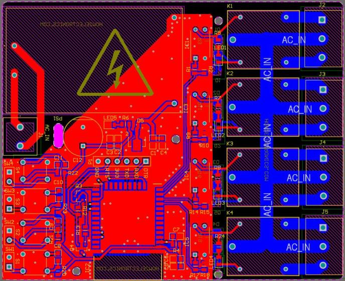
We have designed the PCB using the Altium Designer Software. It took quite a lot of time fixing all the isses in the PCB but still we managed to design a complete working custom PCB.
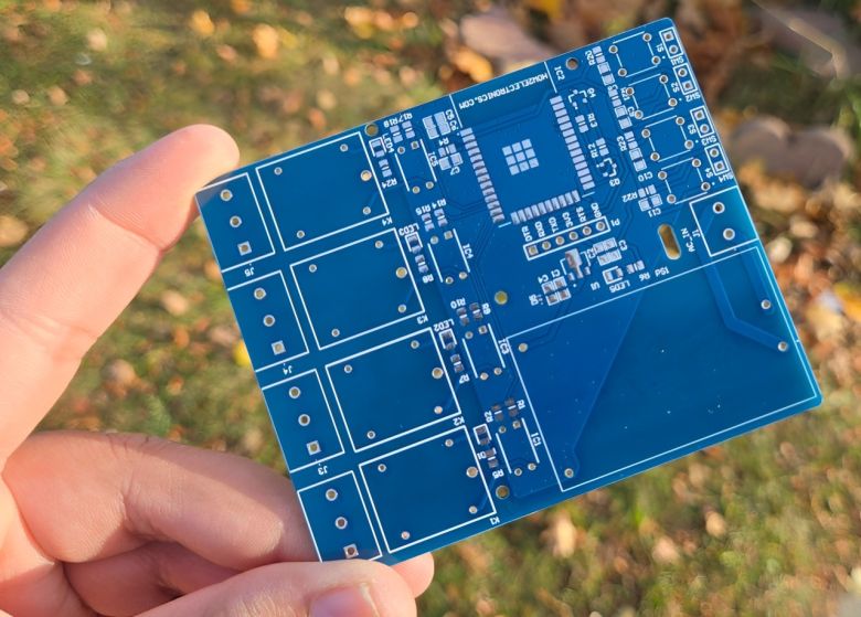
The top part of the PCB design looks like this.
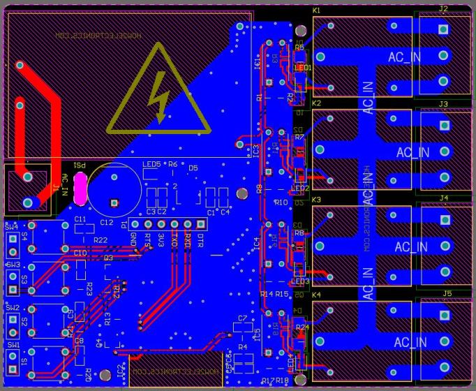
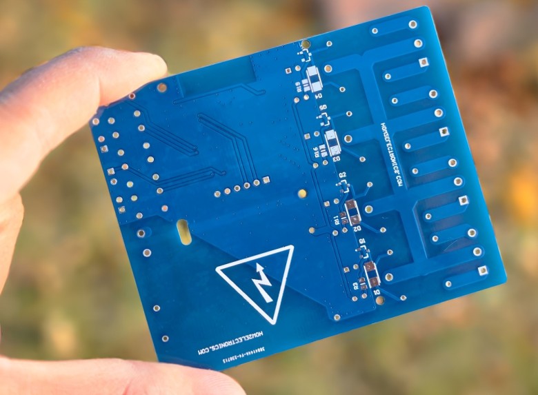
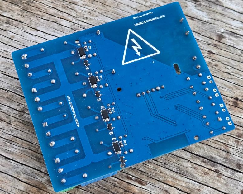
The bottom part of the PCB board looks like this.
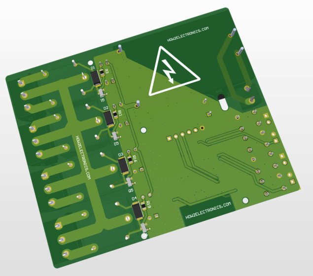
Here is the 3D View of the PCB from the front side.
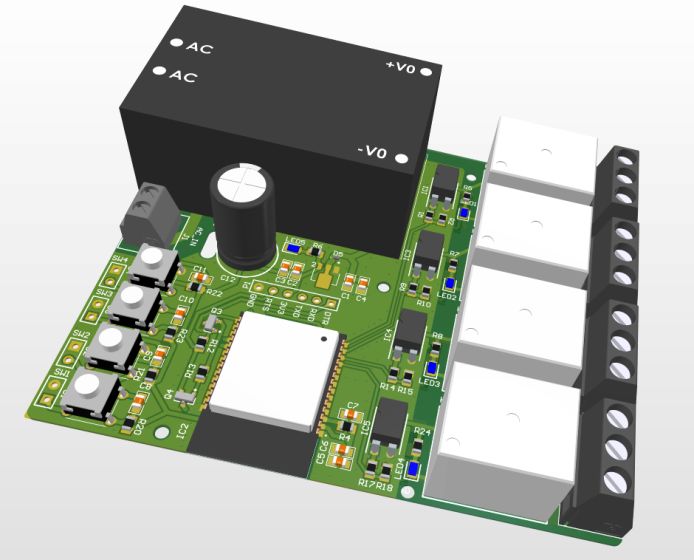
Similarly here is the 3D view of the bottom layer of the PCB Board.
The Gerber File for the PCB is given below. You can simply download the Gerber File and order the PCB from ALLPCB at 1$ only.
You can use this Gerber file to order high-quality PCB for this project. To do that visit the ALLPCB official website by clicking here: https://www.allpcb.com/.

You can now upload the Gerber File by choosing the Quote Now option. From these options, you can choose the Material Type, Dimensions, Quantity, Thickness, Solder Mask Color and other required parameters.
After filling all details, select your country and shipping method. Finally you can place the order.
PCB & Hardware Assembly
After ordering the PCB, it took almost 5 days and I got my PCB.
The PCB quality from ALLPCB is superb with very premium quality. That is why most people trust ALLPCB for PCB/PCBA Services.
First solder all the SMD components like resistors, capacitors, transistors, LEDs, voltage regulators & diodes. Be careful about the SMD LED polarity, place it in the proper direction. The SMD soldering is to be done on the both sides.
After soldering all these, you can solder the ESP32 raw chip. The final stage would be soldering all the through-hole components like Optocoupler IC, terminal block, Relays, male-female headers, and AC-to-DC Converter Module.
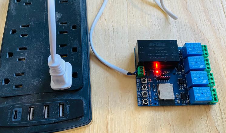
After soldering all the components, the ESP32 KME Smart IoT Home Automation Board is ready for the test. You can upload a blink sketch by connecting a USB-to-TTL Converter Module.
Note: There were some voltage fluctuation issues in the designed PCB, so I have updated the design by adding 220uF capacitor. Also, some connection issues have been fixed. The Gerber file above is updated and the PCB would be little different from shown above. But overall the functionality is same.
Preparing the ESP32 Chip for KME Smart Platform support
For this project, there is no coding requirement. Therefore we don’t need to write any code to the ESP32 microcontroller. Still we need to configure the ESP32 to work with the KME Smart App.
First we need to download the KMESmart Config file. For that go to the following link: kmeconfig.html.
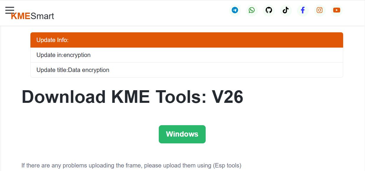
Download the latest available zip file available.
After downloading is completed, extract the file.
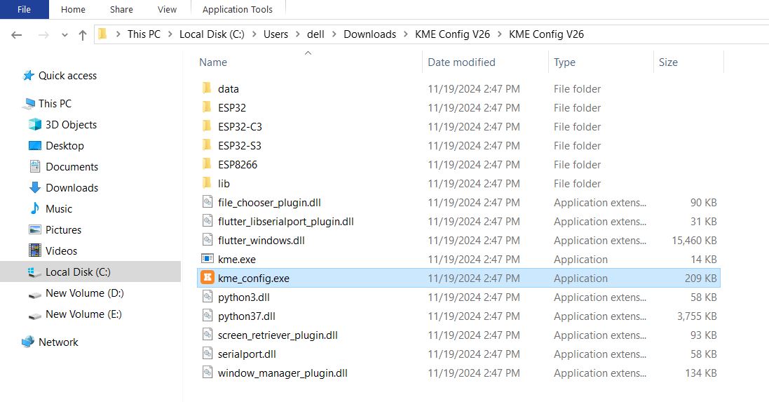
On the extracted folder, there is an executable file with the name “kme_config.exe“. Run this file by double clicking on it.
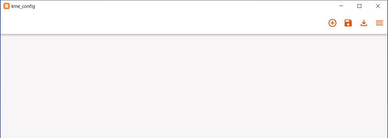
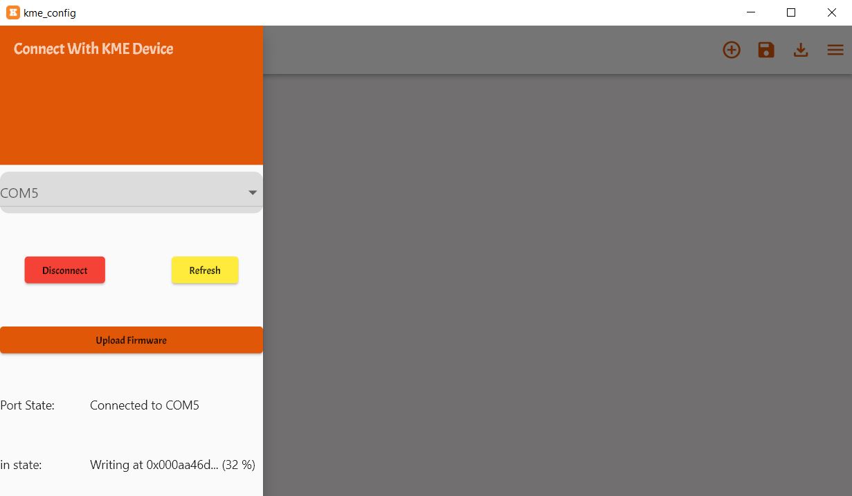
The KME Config software will open as shown in the image above. From here we need to configure our ESP32 Board.
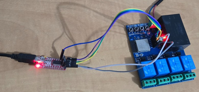
Connect the ESP32 Board to the computer using the micro-USB Cable. In my case, I am using a PCB board, therefore I have connected it to the computer via FTDI Module.
On the KME Config app. Click on the 3 dash on the top right side.
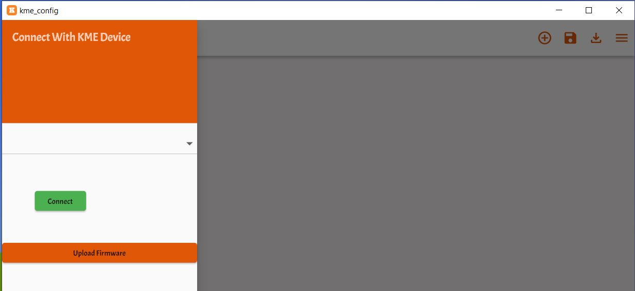
From here, Select the COM port which your ESP32 is connected to.

Now click on upload firmware. The firmware uploading process on ESP32 board will start. You can see everything in progress bar as percentage.
Once the firmware is uploaded, the ESP32 MAC ID and Device ID can be seen.
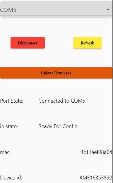
Your ESP32 is now configured to be used with the KME Smart IoT Platform system.
Setting Up KME Smart IoT Dashboard
Now the ESP32 is configured to be used with KME Smart IoT platform but yet not ready for Home Automation System. Therefore we need to setup the dashboard for KME Smart System.
Click on the add sign at the top right of the App. On the left side the widgets will appear.
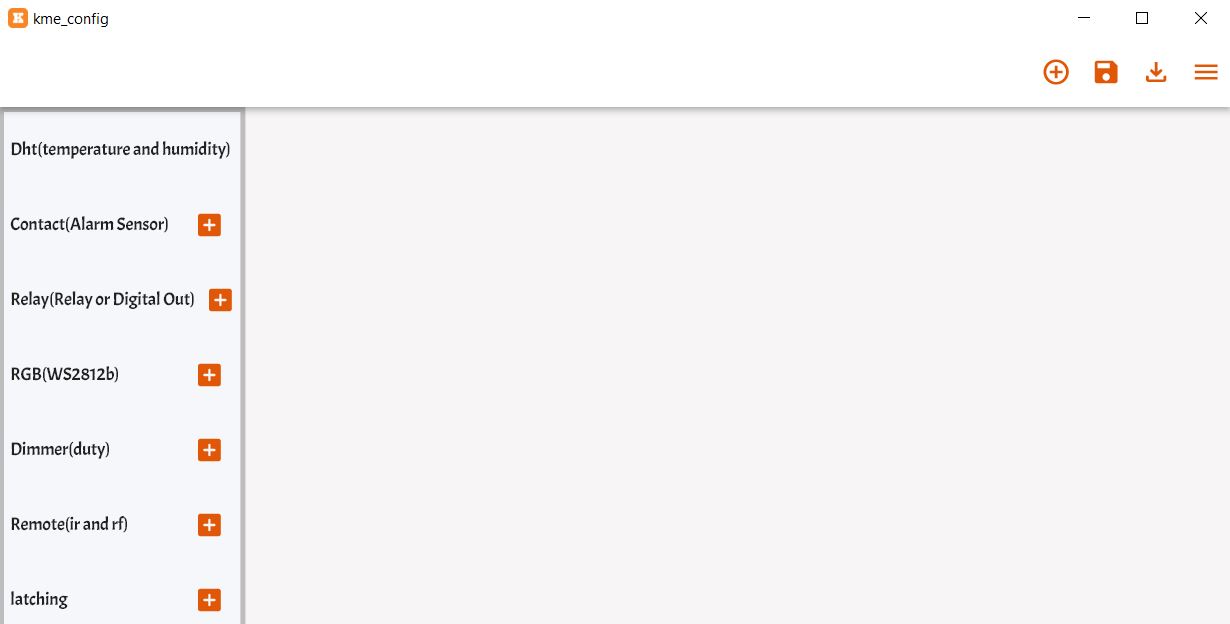
For 4 relays, we need 4 Relay or Digital Output. Therefore add 4 switches from the widgets list.
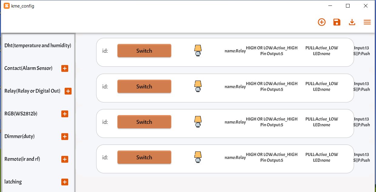
You need to configure all the 4 widgets now. Here are the configuration details that will appear while setting.
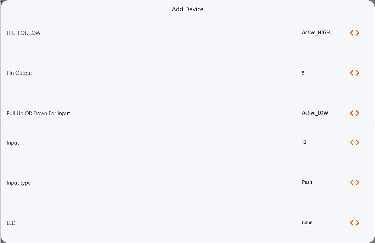
For 4 widgets just change the pin number for Pin Output and Input. The output pin is used for Relay as in the schematic. The input pin is for Push button as shown in the schematic.
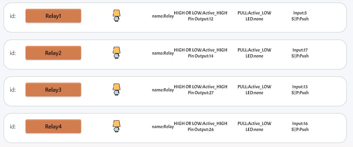
| Relay | Relay Output | Push Button Input |
|---|---|---|
| Relay 1 | 12 | 5 |
| Relay 2 | 14 | 17 |
| Relay 3 | 27 | 13 |
| Relay 4 | 26 | 16 |
Finally the setup is complete as shown here.
Now we need to upload this settings to the ESP32 Board. To upload the settings, click on upload button present at the right bottom on the right side.

Once you see the uploading done message, you are ready to go.
Setting Up KME Smart IoT App on Mobile Phone
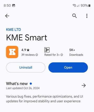
Now, we need to set up the KME Smart IoT Mobile Application that can communicate with the ESP32 Home Automation Board. To do so, go to your phone’s Play Store or App Store and download the KME Smart App.
Open the App. Create an Account using your Email. Then finally you can log in. Upon login, nothing will appear on the app, it will appear blank.

Click on the “+” sign and it will come up with 3 options.
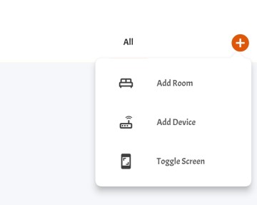
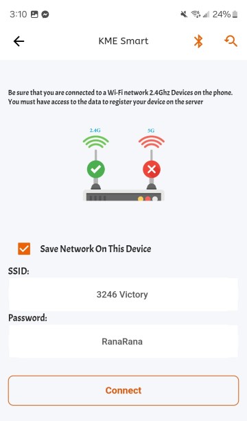
Click on Add Device. A dashboard will appear where you need to enter your WiFi credentials. Enter the Credentials so that ESP32 can connect to the WiFi Network using them.
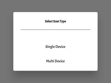
Click on Connect. It will ask you to choose a device type. Choose Single Device.
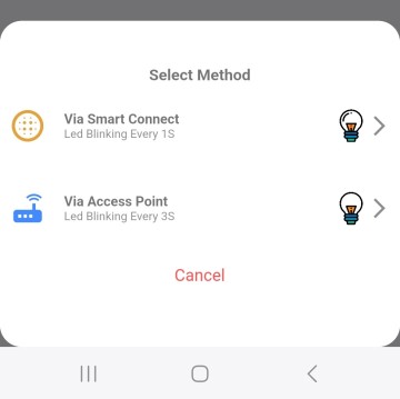
Now a window will pop up asking you to choose the method to connect to the WiFi Network. Either connect it via Smart Connect or via Access Point. In our case, we will connect it via Smart Connect.
For that, you need to put the ESP32 in Boot Mode. Long press the Boot button on ESP32 for a few seconds, and the blue LED will start to blink for 3 seconds.
On the App, Click on Connect via Smart Connect. A window will appear after a while which shows the ESP32 device automatically connected WiFi Network.
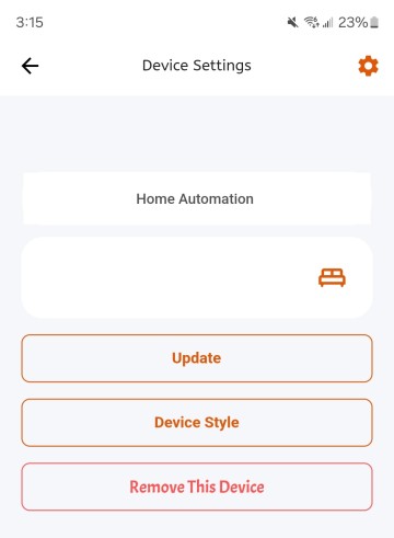
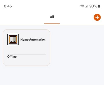
You may update the App Name, such as Home Automation.
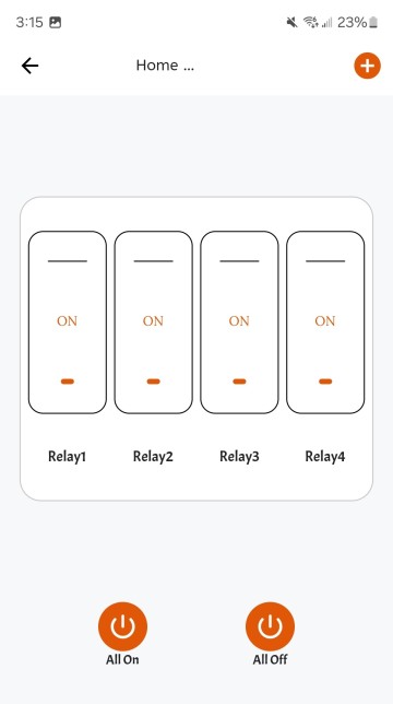
On clicking the App, the dashboard will be available for use. It is shown here.
Testing the KME Smart IoT Home Automation System
By completing all the above steps the ESP32 Home Automation system is ready for testing with KME Smart IoT App.
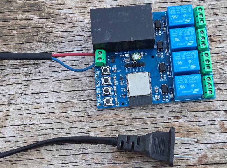
For that, connect the Home Automation Board to the 110/220V power supply.
To test the Home Automation System, press the Relay buttons on Mobile Dashboard.
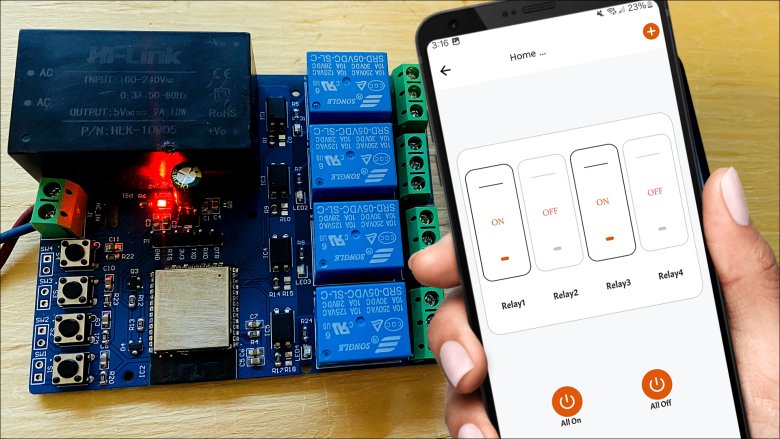
To control the Relays, send ON/OFF commands to each relay individually to verify their operation. You may send “All ON” and “All OFF” command respectively.
This is how you can make a ESP32 Home Automation System using the KME Smart IoT Platform.
 & Live Dashboard")


