

Overview
In this tutorial, we will learn how to Control Relay/LED/Lamp with Amazon AWS IoT Core using ESP32 WiFi Module. Earlier we learned about Getting Started with AWS IoT Core with ESP32 and also ESP8266. The AWS IoT Core is a managed cloud service that lets connected devices easily and securely interact with cloud applications and other devices.
This tutorial is all about Controlling Peripherals like AC Appliances like Lamp or LED or any Relay from AWS IoT Dashboard using ESP32 WiFi Module. The tutorial comprises multiple sections
- Setting up ESP32 Hardware
- Signing up & setting the Amazon Web Services
- Installing Necessary Libraries to Arduino IDE & Writing an Arduino Sketch for the project
- Creating a Thing is AWS
- Creating Policy and attaching to Thing
- Generating Certificates
- Modifying Arduino Sketch according to Thing Data & Credentials
- Publish Data from AWS Dashboard
Bill of Materials
We need following components to work on this project. You can purchase all these components from Amazon using the given purchase link.
| S.N. | Components | Quantity | |
|---|---|---|---|
| 1 | ESP32 WiFi Module | 1 | Amazon | AliExpress |
| 2 | LED 5mm Any Color | 1 | Amazon | AliExpress |
| 3 | Resistor 560-ohm | 1 | Amazon | AliExpress |
| 4 | Resistor 1K | 1 | Amazon | AliExpress |
| 5 | 1 Channel 5V Relay Module | 1 | Amazon | AliExpress |
| 6 | Transistor BC547 | 1 | Amazon | AliExpress |
| 7 | Jumper Wires | 10 | Amazon | AliExpress |
| 8 | Breadboard | 1 | Amazon | AliExpress |
Hardware Setup & Connection
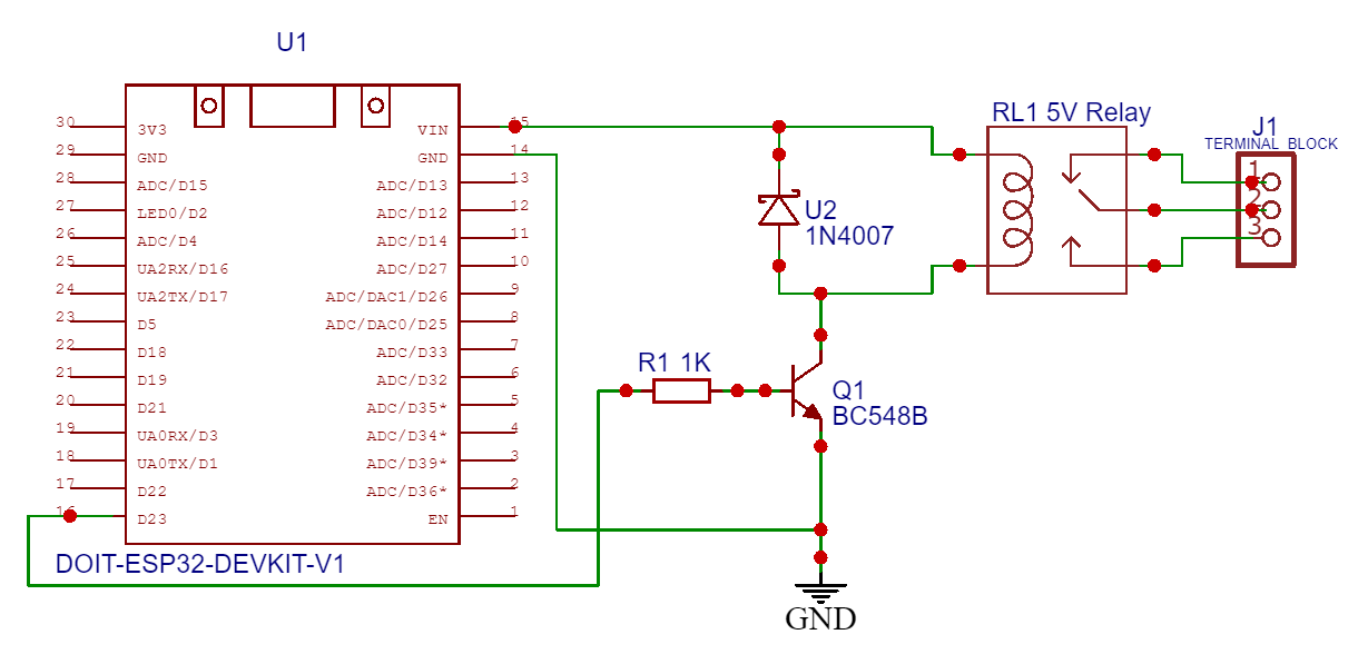
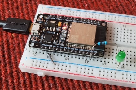
The connection between ESP32 WiFi Module and LED is very simple.

Connect the positive terminal of LED to GPIO23 of ESP32 via a 560-ohm resistor. Connect its negative terminal to GND. You can use a breadboard for connection.

For a simple demo you can use an LED. But if you want to control some AC electrical appliances, you can use the 5V Relay Module. But the Relay doesn’t function using the 3.3V logic as ESP32 GPIO Pin only gives 3.3V output.
Therefore we need to use an NPN transistor which will act as a switch and control the relay even with 3.3V logic. Here is the connection diagram for this part.

Project PCB Gerber File & PCB Ordering Online
If you don’t want to assemble the circuit on a breadboard and you want PCB for the project, then here is the PCB for you. The PCB Board for AWS IoT is designed using EasyEDA online Circuit Schematics & PCB designing tool. First the schematic is designed and then the schematic is converted into PCB.
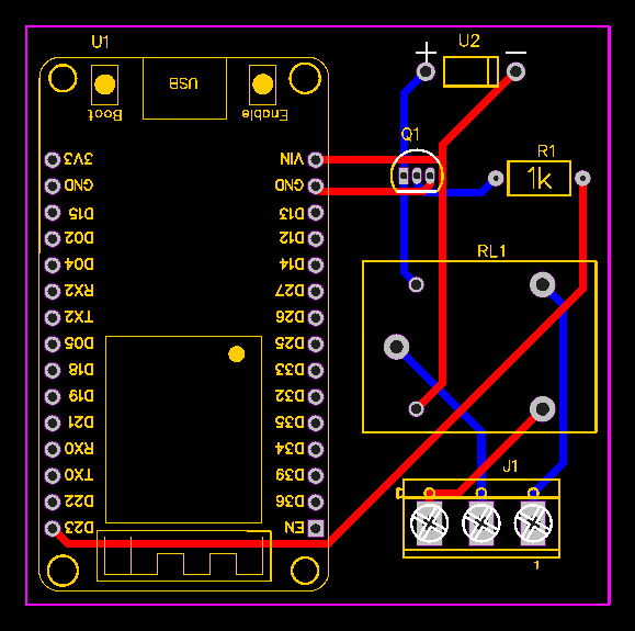
The Gerber File for the PCB is given below. You can simply download the Gerber File and order the PCB from ALLPCB at 1$ only.
You can use this Gerber file to order high quality PCB for this project. To do that visit the ALLPCB official website by clicking here: https://www.allpcb.com/.

You can now upload the Gerber File by choosing the Quote Now option. From these options, you can choose the Material Type, Dimensions, Quantity, Thickness, Solder Mask Color and other required parameters.

After filling all details, select your country and shipping method. Finally you can place the order.
Setting up Amazon AWS IoT Core Dashboard
The signing up part for the Amazon Web Services is already explained in the previous post. You can follow the AWS IoT Core Getting Started tutorial.
After successfully signing in, the AWS Management Console window will open. In the services search tab at the top write ‘IoT core’ & hit enter.

You can click on IoT Core, so an AWS IoT Dashboard will appear now.

On the left side of the dashboard, there are so many options. But we need to work with two options here. One is the manage option and the other one is the secure option.
Creating a Thing
Now we need to create a thing associated with our project. For this, follow the following steps:
- Specifying thing properties
- Configuring device certificate
- Attaching policies to certificate
Under the manage option click on Thing. Now we need to create a Thing here. So, click on Create Things here.

You can select whether create a single thing or create many things. But for our applications, select create a single thing. Then click on Next.

Specify Thing Properties
Here we need to specify the Thing properties. First, give a thing name. You can name it anything. For example, I will name it ESP32_LED.
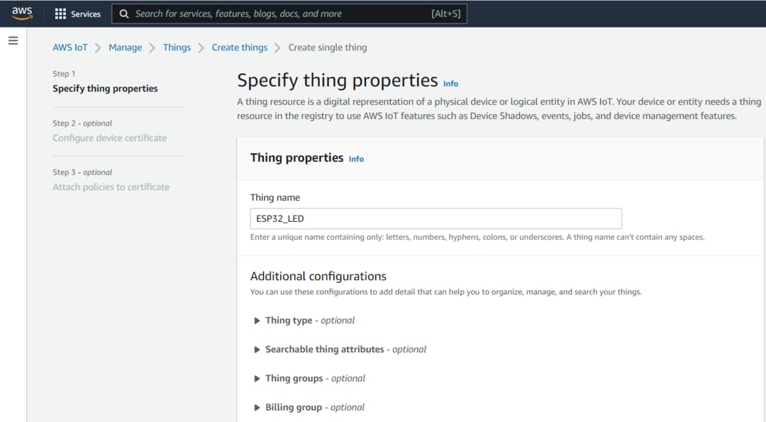
Under additional configurations, there is no need to make any changes.
Under the device shadow option, select the first option as No shadow. Then click on Next.
Generate Device Certificate
Now you need to configure device certificate. So here you can auto-generate a new certificate or use your own certificate or upload CSR or skip this.

But the AWS recommendation is to select the Auto Generate New Certificate. Then click on Next.
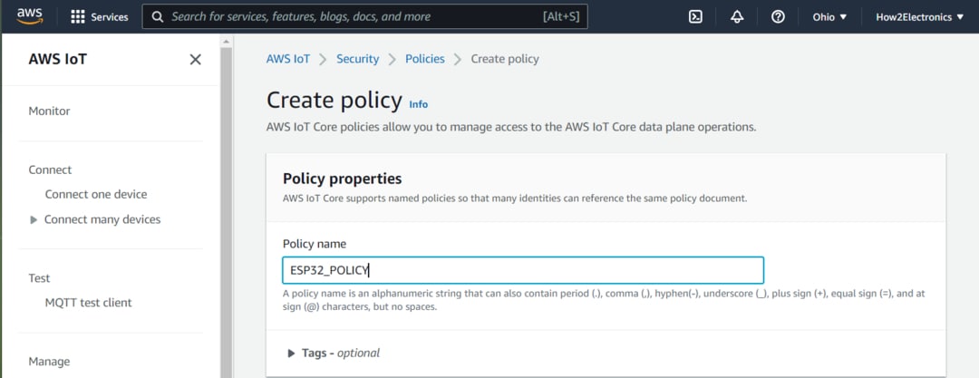
Create & Attach Policy
Now we need to attach a policy to the Things we created. But no policies are here right now. So we need to create a policy first.

So click on create policy. Here give any name to the policy. For example, I will give it a name as “ESP32_Policy“.
Now the add statement part is very important. Under the action, type IoT. So multiple options will pop up. From here we will only need to Subscribe, Connect and Receive.

Now click on create to create the policy. So the policy has been created successfully.
Now go back to Create Thing option. So a policy option will appear. We need to attach the policies to the certificate. So select the appeared policy and click on create a thing.

Downloading Certificates and Keys
Now we need to download the required certificates from this list.

First, download the device certificate and then rename it as a device certificate for identification.
Also, download the public key and rename it as a public key. Then download the private key and rename it as a private key.
In the Root CA Certificates, there are two certificates here. But we just need a Root CA1 certificate, so download it as well.

So we have downloaded all the certificates that we need for our project.
Source Code/Program
The Source Code/Program to Control Relay/LED/Lamp with AWS IoT Core using ESP32 is written in Arduino IDE. Before moving to the code part, we need to install few libraries to the Arduino IDE. Download the following libraries and add it to the Arduino IDE library folder,
1. Arduino JSON Library: https://github.com/bblanchon/ArduinoJson
2. PubSubClient Library: https://github.com/knolleary/pubsubclient
The code is divided into two sections. One is the main file and the other is the header file.
Main.ino
Open a new sketch in Arduino IDE & paste the following code and save it.
|
1 2 3 4 5 6 7 8 9 10 11 12 13 14 15 16 17 18 19 20 21 22 23 24 25 26 27 28 29 30 31 32 33 34 35 36 37 38 39 40 41 42 43 44 45 46 47 48 49 50 51 52 53 54 55 56 57 58 59 60 61 62 63 64 65 66 67 68 69 70 71 72 73 74 75 76 77 78 79 80 81 82 83 84 85 86 87 88 89 90 91 92 93 94 95 96 97 98 99 100 101 102 103 104 105 |
#include "secrets.h" #include <WiFiClientSecure.h> #include <PubSubClient.h> #include <ArduinoJson.h> #include "WiFi.h" #define AWS_IOT_SUBSCRIBE_TOPIC "esp32/sub" #define lamp 23 WiFiClientSecure net = WiFiClientSecure(); PubSubClient client(net); void connectAWS() { WiFi.mode(WIFI_STA); WiFi.begin(WIFI_SSID, WIFI_PASSWORD); Serial.println("Connecting to Wi-Fi"); while (WiFi.status() != WL_CONNECTED) { delay(500); Serial.print("."); } // Configure WiFiClientSecure to use the AWS IoT device credentials net.setCACert(AWS_CERT_CA); net.setCertificate(AWS_CERT_CRT); net.setPrivateKey(AWS_CERT_PRIVATE); // Connect to the MQTT broker on the AWS endpoint we defined earlier client.setServer(AWS_IOT_ENDPOINT, 8883); // Create a message handler client.setCallback(messageHandler); Serial.println("Connecting to AWS IOT"); while (!client.connect(THINGNAME)) { Serial.print("."); delay(100); } if (!client.connected()) { Serial.println("AWS IoT Timeout!"); return; } // Subscribe to a topic client.subscribe(AWS_IOT_SUBSCRIBE_TOPIC); Serial.println("AWS IoT Connected!"); } void messageHandler(char* topic, byte* payload, unsigned int length) { Serial.print("incoming: "); Serial.println(topic); StaticJsonDocument<200> doc; deserializeJson(doc, payload); const char* message = doc["message"]; Serial.println(); for (int i = 0; i < length; i++) { Serial.print((char)payload[i]); // Pring payload content } char led = (char)payload[62]; // Extracting the controlling command from the Payload to Controlling LED from AWS Serial.print("Command: "); Serial.println(led); if (led == 49) // 49 is the ASCI value of 1 { digitalWrite(lamp, HIGH); Serial.println("Lamp_State changed to HIGH"); } else if (led == 48) // 48 is the ASCI value of 0 { digitalWrite(lamp, LOW); Serial.println("Lamp_State changed to LOW"); } Serial.println(); } void setup() { Serial.begin(115200); connectAWS(); pinMode (lamp, OUTPUT); digitalWrite(lamp, LOW); } void loop() { client.loop(); delay(1000); } |
Secrets.h
Open a New Tab in Arduino IDE and name it as Secrets.h. And paste the following code to this file.
|
1 2 3 4 5 6 7 8 9 10 11 12 13 14 15 16 17 18 19 20 21 22 23 24 25 26 27 28 29 30 31 32 |
#include <pgmspace.h> #define SECRET #define THINGNAME "***********" //change this const char WIFI_SSID[] = "***********"; //change this const char WIFI_PASSWORD[] = "***********"; //change this const char AWS_IOT_ENDPOINT[] = "***********"; //change this // Amazon Root CA 1 static const char AWS_CERT_CA[] PROGMEM = R"EOF( -----BEGIN CERTIFICATE----- -----END CERTIFICATE----- )EOF"; // Device Certificate //change this static const char AWS_CERT_CRT[] PROGMEM = R"KEY( -----BEGIN CERTIFICATE----- -----END CERTIFICATE----- )KEY"; // Device Private Key //change this static const char AWS_CERT_PRIVATE[] PROGMEM = R"KEY( -----BEGIN RSA PRIVATE KEY----- -----END RSA PRIVATE KEY----- )KEY"; |
Modifying Arduino Sketch according to the Thing
Now it’s time to modify the Arduino Sketch File. Go to secrets.h tab and begin the modification.
Here we need to include a thing name. You can go to the things section of AWS Console and copy the thing name.

Paste the thing name to the following line of code.
|
1 |
#define THINGNAME "***************" |
Under the WiFi SSID and password, enter the WiFi SSID and Password of your local network.
|
1 2 |
const char WIFI_SSID[] = "***************"; const char WIFI_PASSWORD[] = "***************"; |
Now, we need to insert the AWS IoT Endpoint here. To get the endpoint, go to the settings part of AWS Dashboard. Yow will get the endpoint.

Click on the copy icon to copy the endpoint. Go back to Arduino IDE and paste it on the following line.
|
1 |
const char AWS_IOT_ENDPOINT[] = "***************"; |
You need to insert the Amazon Root CA1 in between the following line.
|
1 2 3 4 5 6 |
// Amazon Root CA 1 static const char AWS_CERT_CA[] PROGMEM = R"EOF( -----BEGIN CERTIFICATE----- -----END CERTIFICATE----- )EOF"; |
So for this, we need to go back to the certificate that we downloaded earlier. Open this file with Notepad++ and copy all the text.

Then go back to Arduino IDE and insert the copied text between begin certificate and the end certificate.
Under the “Device Certificate” lines, we need to paste the device certificate text. So open the device certificate file that we downloaded earlier. And again copy the text and paste it between the begin certificate and end certificate section.
|
1 2 3 4 5 |
// Device Certificate static const char AWS_CERT_CRT[] PROGMEM = R"KEY( -----BEGIN CERTIFICATE----- -----END CERTIFICATE----- |
Under the “Device Private Key“, we need to insert the device’s private key. So go to the downloaded folder again and open the device’s private key file using Notepad++. Again copy the text and paste it between begin & end parts.
|
1 2 3 4 5 |
// Device Private Key static const char AWS_CERT_PRIVATE[] PROGMEM = R"KEY( -----BEGIN RSA PRIVATE KEY----- -----END RSA PRIVATE KEY----- |
So all the modification of the Arduino Sketch for AWS IoT Lamp/LED/Relay is done now.
Control Relay/LED/Lamp with AWS IoT Core using ESP32
Once all the modification is done, connect the ESP32 to your computer. Then go to the tools & select ESP32 Board that you are using for this project. Also, select the COM port. Then click on the upload option to upload the code to the ESP32 board.

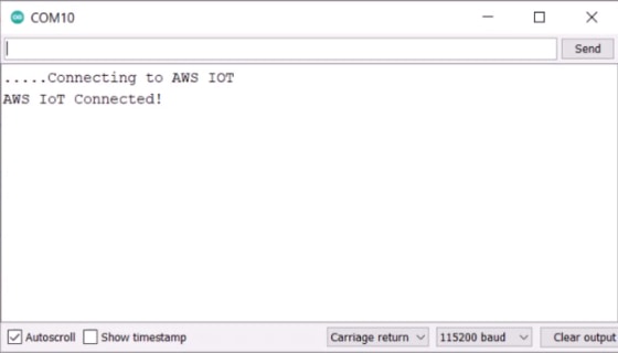
Once the code uploading is done, open the Serial Monitor. The ESP32 will try connecting to the WiFi Network. Once it gets connected to the WiFi Network, it will try connecting to the AWS IoT Server. The Serial Monitor will show this message.
Now we need to check whether we are able to publish the topic to control an LED or not.
To do that, you need to publish a topic. For that type “esp32/sub“ under the topic filter section. Under Message Payload type the following command.
|
1 2 3 4 |
{ "message": "Hello from AWS IoT console" "led_Control": "1" } |
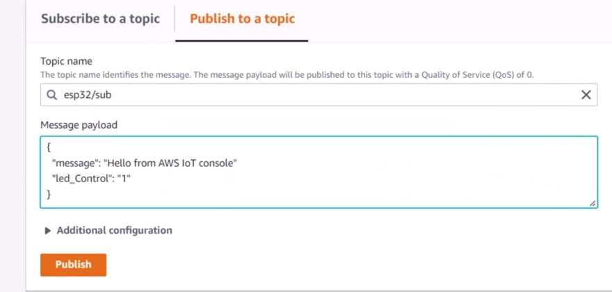
Under additional configuration do nothing. Then click on publish. Immediately you can see the message sent to the Serial Monitor.
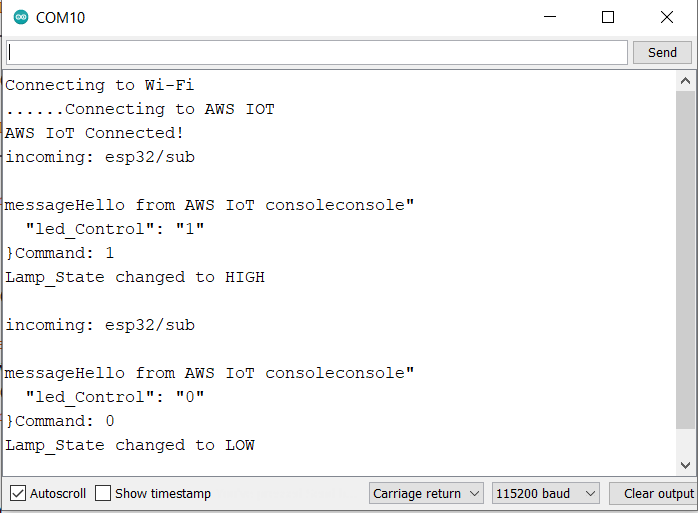
At this moment the LED will turn on immediately.

Now to turn OFF the LED send 0 instead of 1 from the publish window of AWS Dashboard. The LED should turn off immediately.
This is how you can control Relay/LED/Lamp with Amazon AWS IoT Core using ESP32 WiFi Module. The demo is done with LED. Instead of the LED, you can control any appliances through Relay. The advanced version of this project is AWS IoT Home Automation project.
Video Tutorial & Guide


1 Comment
Great Tutorials, thank You -:)