

Overview
In this project, we will make an ESP32 DW1000 UWB-based Indoor Location Positioning System. For this, we will use 2 UWB Anchors and 1 UWB Tag. When the tag is moving, the real-time position of the UWB tag can be graphically displayed on the PC using the Python program.
Indoor tracking in industrial environments often requires very precise localization. For this purpose, we offer solutions based on the short-range radio technology Ultra-wideband (UWB). It does not work with consumer standards such as Wi-Fi and Bluetooth Low Energy but offers accuracy better than 30 cm.

The ESP32 UWB (Ultra Wideband) Module from Makerfabs is most popular UWB Module in the Market. The Module is based on Decawave DW1000 UWB Chip. In the previous Getting Started Tutorial, we learned about board design, specifications, DW1000 Library, program/code, antenna delay calibration and method to measure short distances.
This tutorial covers the method to use ESP32 UWB (Ultra Wideband) board as an Anchor and Tag to find the Indoor Positioning of an object. You can also refer to ESP32 DW3000 UWB Board which is interoperable with the Apple U1 chip.
Bill of Materials
To make Indoor Positioning System using UWB technology, we need the following components.
| S.N. | Components | Quantity | Purchase Links |
|---|---|---|---|
| 1 | ESP32 DW1000 UWB Module | 3 | Makerfabs |
| 2 | Micro-USB Cable | 3 | Amazon | AliExpress |
| 3 | Power Bank 5V | 3 | Amazon | AliExpress |
What is UWB (Ultra Wideband)?
UWB is a short-range, wireless communication protocol similar to Bluetooth or Wi-Fi. It also uses radio waves for communication & operates at a very high frequency. As its name denotes, it also uses a wide spectrum of several GHz. One way to think of it is as a radar that can continuously scan an entire room and precisely lock onto an object like a laser beam to discover its location and communicate data.

The primary purpose of Ultra Wideband is location discovery and device ranging. While both Wi-Fi and Bluetooth have been modified to allow greater accuracy in locating other devices and connecting to them, UWB is natively more precise & uses less power.
UWB Ranging & Time of Flight
A UWB transmitter works by sending billions of pulses across the wide spectrum frequency. A corresponding receiver receives the signal, which translates the pulses into data by listening for a familiar pulse sequence sent by the transmitter. Pulses are sent about one every two nanoseconds, which helps UWB achieve its real-time accuracy.

UWB is extremely low power. Its high bandwidth (500MHz) is ideal for relaying a lot of data from a host device to other devices up to about 30 feet away. Unlike Wi-Fi, it is not particularly good at transmitting through walls.
When a smartphone with a UWB chip comes close to another UWB device, the two starts ranging or measuring, their exact distance. The ranging is accomplished through “Time of Flight” (ToF) measurements between the devices. These are used to calculate the roundtrip time of challenge/response packets.
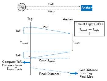
The concepts “anchor” and “tag” are important to understand distance and location measurement with UWB. An anchor is generally a fixed UWB device with a known location. A tag generally refers to a mobile UWB device. An anchor and tag exchange information to establish the distance between them. The exact location of a tag can be determined by communicating with multiple anchors. Some devices can act as either an anchor or tag.
In either 3-message mode or 4-message mode, the flight time is calculated as:

We will be using the same method for our ESP32 UWB Indoor Positioning Calculation.
ESP32 UWB(Ultra Wideband) Board
The ESP32 UWB Ultra Wideband module is based on DW1000 and ESP32. This board is manufactured by Makerfabs. The BU01 Module based on DW1000 Chip is interfaced with ESP32 WiFi Module with I/O expansion. The board acts like a continuously scanning radar, that precisely locks onto another device (called Anchor) and communicates with it, thus calculating its own location.

The top side of the board has ESP32 WROOM/Wrover Module embedded with BU01 Module with other passive electronic components. There are two push buttons, one for flash and the other for rest. The board has a micro-USB port for uploading the firmware and Serial Communication.

On the backside of the board, there is CP2102 Chip for UART communication. The name of the input/output ports is also assigned on the board. The male or female headers can be soldered on both sides of the board. The board is breadboard friendly. Hence you can place it on a breadboard with other components during practical applications.
Indoor Location Positioning System with ESP32 UWB
Positioning System
In this Indoor Location Positioning System, we will use 3 ESP32 UWB modules. The 2 modules will act as the UWB anchor, and 1 as the UWB tag. The two anchors are stationary whereas the tag is movable.

As the tag gets its position, it transmits its location to devices(either PC browser, or the app on phone), to show the real-time position.
Plane orientation algorithm
Let us assume that all three UWB modules are at the same horizontal height. UWB can get the distance between Tag and two anchors, plus the distance of two anchors set in advance, we can get the length of three sides of a triangle.
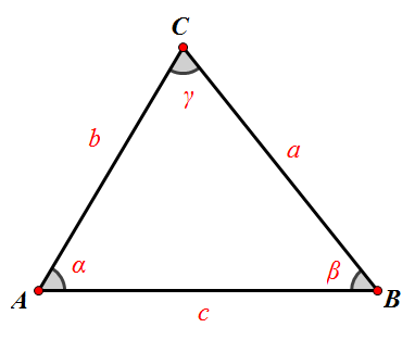
Two points “AB” are two anchors respectively, and “C” is the point of tag. “c” is the distance of two anchors, and UWB will get two lengths “a” and “b”. Tag is “b” away from point “A” and “a” away from point “B”.
Now that we know the distance between the three sides of the triangle, we can calculate the coordinates of point “C”.
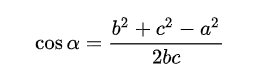
I used the law of cosines to calculate the cosine of Angle “A”:
I have the Pythagorean Theorem that gives me the sine of Angle “A”:
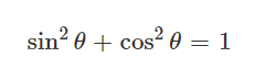
sin_a = sqrt(1 – cos_a * cos_a)
If we set point “A” as the origin of the coordinate system (0,0), then we get to point C (bcosα, bsinα).
Installing DW1000 Library
First we need to install Arduino-DW1000 Library from thotro. This library offers functionality to use Decawave’s DW1000 chips/modules with Arduino.

You can also install this library through the library manager. Just search for DW1000 and click on install to install the library.
The DW1000 UWB library doesn’t compile for ESP32 Boards directly. Therefore we need to make some modifications in the library part.
Go to the Arduino Library folder and look for DW1000. Then open the Library folder and look for the source folder (src).

Open the src folder and look for DW1000.cpp file. Open the file with some text editor like Notepad++.
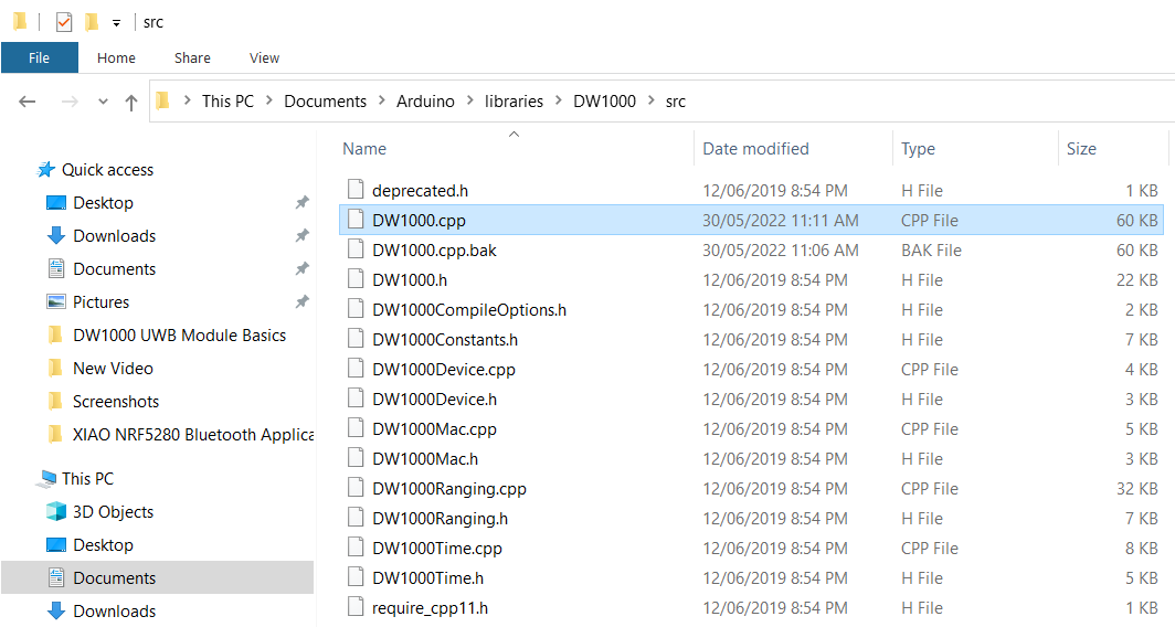
Now look for the following lines (Line No. 172) and comment on all these 3 lines.
|
1 2 3 |
//#ifndef ESP8266 // SPI.usingInterrupt(digitalPinToInterrupt(irq)); // not every board support this, e.g. ESP8266 //#endif |

Once these lines are commented, the library code will successfully compile.
Source Code/Program
We are using 3 UWB Modules, therefore we need 3 different code for the modules, i.e. two for anchors and one for tag. For visulization of the position we need Python Code.
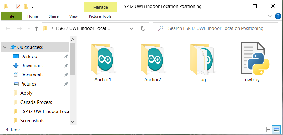
The complete code for the ESP32 UWB Indoor Positioning project can be downloaded from the following link:
Anchors Code
As there 2 anchors in the system, we need to set different anchor addresses for the two anchors.
|
1 |
#define ANCHOR_ADD "83:17:5B:D5:A9:9A:E2:9C"// modify the address when multiple anchors, such as 83/82. |
The library uses random short addresses by default, and we need to set it to use the static addresses we set. So we need to set the UWB module to Anchor mode, LONGDATA_RANGE_LOWPOWER mode, and turn off random short addresses, by the following code:
|
1 2 |
DW1000Ranging.startAsAnchor(ANCHOR_ADD, DW1000.MODE_LONGDATA_RANGE_LOWPOWER, false); |
Tag Code
Tag needs to read the distance between the two anchors and send it to PC through UDP protocol.
In the tag code we need to change the WiFi SSID, Password & Computer IP Address.
|
1 2 3 |
const char *ssid = "*************"; const char *password = "*************"; const char *host = "*************"; |
To get the Computer IP Address, type ipconfig in CMD window,
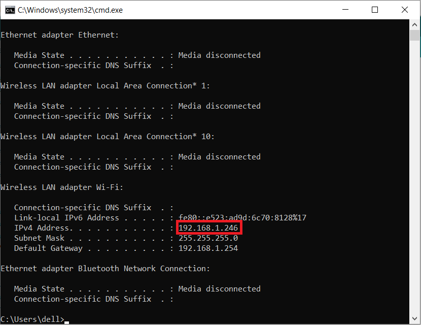
Copy the IP Address from the CMD window & paste in your code.
Python Code
A simple demo to calculate the position of the tag and graphically display it. We used turtle to draw.
Some drawing functions are added to quickly draw lines, circles, rectangles, etc.

Here is the position calculation function in the Python Code.
|
1 2 3 4 5 6 7 8 9 10 |
def tag_pos(a, b, c): # p = (a + b + c) / 2.0 # s = cmath.sqrt(p * (p - a) * (p - b) * (p - c)) # y = 2.0 * s / c # x = cmath.sqrt(b * b - y * y) cos_a = (b * b + c*c - a * a) / (2 * b * c) x = b * cos_a y = b * cmath.sqrt(1 - cos_a * cos_a) return round(x.real, 1), round(y.real, 1) |
The function of the demo is to receive the data of the tag transmitted through the UDP protocol, calculate the position of the tag and draw it on the screen.
Testing ESP32 UWB Indoor Positioning
.First upload the anchor code on both the ESP32 UWB anchor. Remember the anchor adrress should be the different.
Ater uploading the tag code, open both Serial Monitors on a different port and press the reset button on both modules. You will see the following message on the screen.
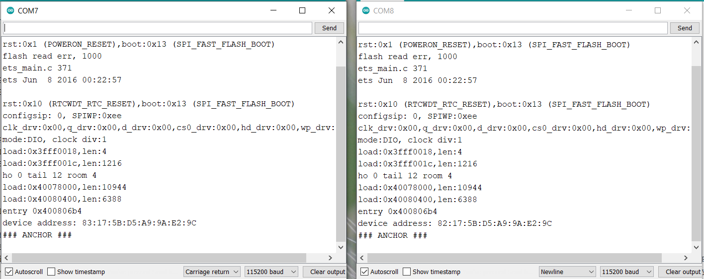
Then upload the tag code on the 3rd ESP32 UWB Module. After uploading the code press the Reset button. The following message will appear on the Serial Monitor.

The ESP32 Tag will calculate the distance from both the anchors. The obtained string will be in JSON format.
For the visulization part we need to run the Python Script. You can use any Python editor like Thonny IDE.
Run the Python code & again press the reset button on Tag Module. In the Python Shell, you will receive the following message.
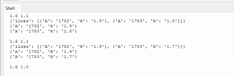
Immediately a window will pop up showing the positions of Anchors and Tag & also the distances between them.

You can place two anchors at different distances and move the Tag in any direction. The coordinates on the Python Pop-up screen will move indicating the position along with the distances.

Remember the Tag should be connected to the WiFi network so that it would transfer the data to Python through UDP protocol.
Thus this is how you can make Indoor Location Positioning System using ESP32 DW1000 UWB Module. If you want to get 200 meter distance you may try ESP32 UWB Pro board which has an amplifier.
Video Tutorial & Guide

You may also refer to some of our previous articles related to UWB Technology using DW1000/300 Chip to have a more clear understanding:
- Getting Started with ESP32 DW1000 UWB Module
- ESP32 UWB Pro – Ultra Wideband Module with Amplifier
- ESP32 DW3000 UWB Module Achieving 500m Range


8 Comments
Hi, I want to ask a question. Why can’t my tag connect with my PC? The WiFi is successfully connected to the tag, but when the code “client.connect(host, 80),” it does not connect to my PC, which is running a Python program.
Hi, I’m trying to follow with the steps using the code provided on this article as well! If I understand correctly, are you referring to this issue?
sock.bind((UDP_IP, UDP_PORT))
PermissionError: [Errno 13] Permission denied
If yes, then this might have to do with the issues of privileged ports where anything below 1024 requires administrative permissions (something along those lines, am not an expert just based on what I googled). Not sure if it will work for you, but I used a random port number of 8000 for both the codes on uwb.py and tag.ino and it worked for me!
*If you also experience an issue whereby the UDP_IP in uwb.py gives u a wrong local address, I manually replaced it with my own IP address to make it work.
Hope this helps!
Hi I have a question Admin! I have attempted and got everything to work up to the visualization point! Looks quite good appreciate your article on this! However, the distance measured is not accurate and how should I go about correcting this?
I have issuse connecting tag to wifi. pls help me.
Same issue here. Help me
I am looking for a sample tdoa code but I couldn’t find it. How can I find a sample code for TDoA?
Hello ,
Iam looking for same kind of algorithm for 2 anchors, 2 tags, please help me on this
the tag didnt shows range but shows connected,shows only “links”