

Overview
In this getting started tutorial, we will learn about the Ultra Wideband Technology using ESP32 DW3000 UWB Module. Ultra-wideband (UWB) is a short-range, wireless communication protocol that operates through radio waves, and enables secure reliable ranging and precision sensing, creating a new dimension of spatial context for wireless devices.
The IC DecaWave DW3000 UWB Transceivers chip allows finding the location of objects to a precision of 10cm. The DW3000 Chip has worldwide UWB support through its operation on UWB channel 5 (6.5GHz) and channel 9 (8GHz). The DW3000 is interoperable with the Apple U1 chip, which makes it possible to work with the Apple ecosystem.
In this tutorial, we will go through the board design, specifications, and applications. Then we will learn how to use the ESP32 DW3000 board for High-Accuracy Ranging and Localization.
Before moving ahead, refer to some of our previous articles related to UWB Technology using DW1000 Chip to have a more clear understanding:
- Getting Started with ESP32 DW1000 UWB Module
- ESP32 DW1000 UWB Indoor Location Positioning System
- ESP32 UWB Pro – Ultra Wideband Module with Amplifier
- ESP32 DW3000 UWB Module Achieving 500m Range
Bill of Materials
We need the following components for this project. You can purchase the components from the given links.
| S.N. | Components | Quantity | Purchase Links |
|---|---|---|---|
| 1 | ESP32 DW3000 Board | 2 | Makerfabs |
| 2 | 0.96" OLED Display | 1 | Amazon | AliExpress |
| 3 | Micro-USB Cable | 2 | Amazon | AliExpress |
| 4 | Breadboard | 1 | Amazon | AliExpress |
| 6 | Jumper Wires | 10 | Amazon | AliExpress |
What is Ultra Wideband & how does it work?
UWB is a short-range, wireless communication protocol similar to Bluetooth or Wi-Fi. It also uses radio waves for communication & operates at a very high frequency. As its name denotes, it also uses a wide spectrum of several GHz. One way to think of it is as a radar that can continuously scan an entire room and precisely lock onto an object like a laser beam to discover its location and communicate data.

The primary purpose of Ultra Wideband is location discovery and device ranging. While both Wi-Fi and Bluetooth have been modified to allow greater accuracy in locating other devices and connecting to them, UWB is natively more precise & uses less power.
A UWB transmitter works by sending billions of pulses across the wide spectrum frequency. A corresponding receiver receives the signal, which translates the pulses into data by listening for a familiar pulse sequence sent by the transmitter. Pulses are sent about one every two nanoseconds, which helps UWB achieve its real-time accuracy.

The concepts “anchor” and “tag” are important to understand distance and location measurement with UWB. An anchor is generally a fixed UWB device with a known location. A tag generally refers to a mobile UWB device. An anchor and tag exchange information to establish the distance between them. The exact location of a tag can be determined by communicating with multiple anchors. Some devices can act as either an anchor or tag.
DW3000 UWB Transceivers Chip
The DW3000 chip is a microcontroller chip produced by the company Decawave. It is used in the development of ultra-wideband (UWB) wireless technology for location-based services and precision indoor positioning. The chip is designed for use in applications such as asset tracking, industrial automation, and robotics. It utilizes time-of-flight (ToF) measurement to determine the distance between devices, which allows for precise positioning and location tracking.
The module has worldwide UWB support through its operation on UWB channel 5 (6.5GHz) and channel 9 (8GHz). The DW3000 is Optimized for low-power battery-operated operation and has much lower Power consumption, almost 1/3 of the DW1000.
Features of DW3000
- Interoperable with Apple U1 chip
- Supports UWB channels 5 (6.5GHz) and 9 (8GHz)
- Fully aligned with FiRa™ PHY, MAC, and certification development
- Integrated UWB IC, UWB chip antenna, power management, and crystal simplifies design integration
- Optimized for Low Power battery operation
- Allows for cost-effective implementation of UWB solutions
- Supply voltage: 2.5 to 3.6V (VDD3V3), 1.62 to 3.6V (VDD1)
Applications of DW3000
- High-precision real-time location systems
- Location-aware wireless sensor networks
- Asset tracking
- Factory/warehouse automation and security
- Healthcare staff and patient location
- Retail security, navigation and customer analytics
- Connected home
ESP32 DW3000 UWB(Ultra Wideband) Board
The ESP32 UWB Ultra Wideband module consists of Decawave DW3000 and ESP32 WiFi Module. This board is manufactured by Makerfabs. The board acts like a continuously scanning radar, that precisely locks onto another device (called Anchor) and communicates with it, thus calculating its own location. The best part about the board is it is interoperable with the Apple U1 chip, which makes it possible to work with the Apple system.

The top side of the board has ESP32 WROOM/Wrover Module embedded with DW3000 Module with other passive electronic components. There are two push buttons, one for flash and the other for rest. The board has a micro-USB port for uploading the firmware and for Serial Communication.
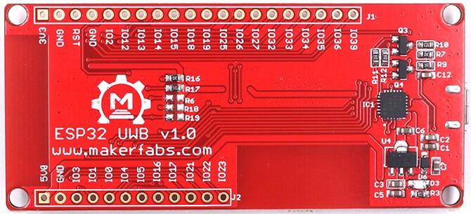
On the backside of the board, there is CP2102 Chip for UART communication. The name of the input/output ports is also assigned on the board. You can use male or female headers & solder on both sides of the board.
DW3000 Library Installation
To use the DW3000 with ESP32 on Arduino IDE, we need a DW3000 library. The DW3000 library offers the functionality to use Decawave’s DW3000 chips/modules with any microcontroller.
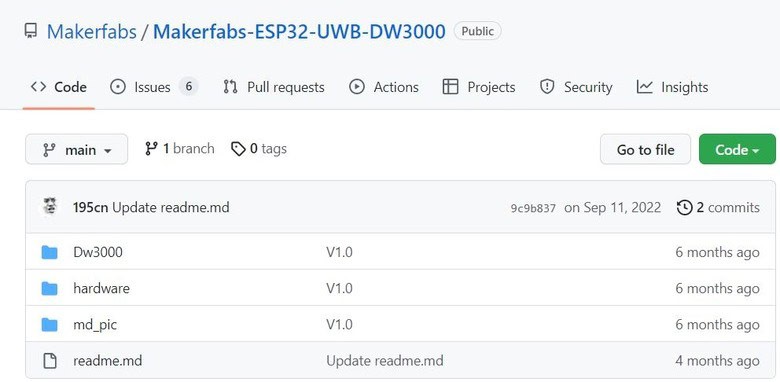
The DW3000 library was developed by NConcepts but you can download it from the following GitHub repository maintained by Makerfabs.
The library supports the transmission of messages, and timestamp handling (for ranging and location sensing applications), and implements the different operation modes the DW3000 has to offer. The library design is intended to offer an easy-to-use interface to the otherwise complex and configuration-intense handling of the DW3000.
Anchor & Tag Hardware Setup
Let’s learn how we can use the ESP32 DW3000 UWB (Ultra Wideband) Board with Arduino IDE and measure the distance between the boards. For this project, you will need pair of boards. One of the boards will act like an Anchor and the other like a Tag.
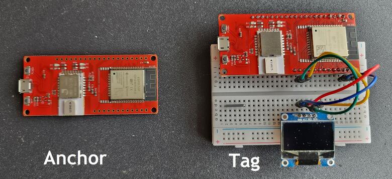
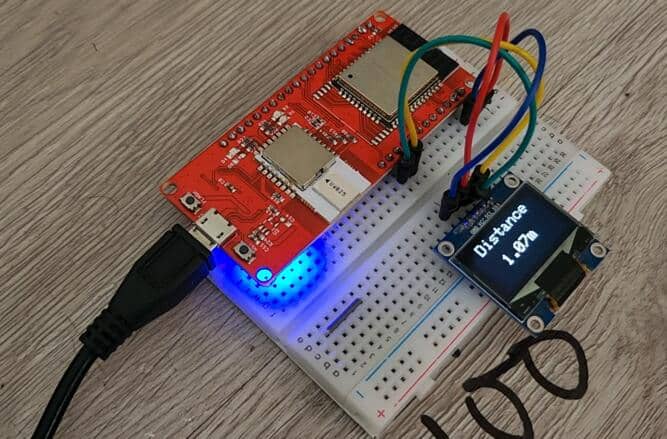
For the Anchor Part, we need nothing except a Micro-USB Cable. But for the tag part, we need a 0.96″ I2C OLED Display and a Powerbank. The I2C OLED will display the distance of the Tag from the Anchor. The Power bank or a battery will provide power to the movable Tag.
On the tag part, connect the 0.96″ I2C OLED display I2C Pins (SDA & SCL) to ESP32 GP21 & GP22 Pin. Connect the VCC & GND Pin of OLED Display to ESP32 3.3V & GND pin.
Source Code/Program for Range Testing
The code that we will use to test the ESP32 DW3000 Board is taken from the library example. Using this example, we can do the range testing which practically lies between a 10-20 meter distance.
Before moving to the testing part, we need to understand the Antenna Delay Calibration. In ultra-wideband (UWB) systems, antenna delay calibration is the process of measuring and compensating for the inherent time delay that occurs between the transmission and reception of a signal due to the physical properties of the antenna. This delay can vary depending on factors such as the frequency of the signal, the size and shape of the antenna, and the distance between the transmitter and receiver. Antenna delay calibration is important for ensuring accurate time-of-flight (ToF) measurements in UWB systems and for improving the overall performance of the system. This can be done by measuring the impulse response of the channel and then compensating for the delay.
For our code part, we have set the default antenna delay values for 64 MHz PRF as 16385. You can modify it according to your UWB Module Behavior & ranging accuracy in the following lines of code.
|
1 2 3 |
/* Default antenna delay values for 64 MHz PRF. See NOTE 2 below. */ #define TX_ANT_DLY 16385 #define RX_ANT_DLY 16385 |
To measure the distance between the boards, we need to upload an “Anchor” code to one ESP32 Board and the “Tag” code to other ESP32 Board.
Anchor Code
Copy the following code and upload it to the first UWB(Ultra Wideband) Board which is the Anchor.
|
1 2 3 4 5 6 7 8 9 10 11 12 13 14 15 16 17 18 19 20 21 22 23 24 25 26 27 28 29 30 31 32 33 34 35 36 37 38 39 40 41 42 43 44 45 46 47 48 49 50 51 52 53 54 55 56 57 58 59 60 61 62 63 64 65 66 67 68 69 70 71 72 73 74 75 76 77 78 79 80 81 82 83 84 85 86 87 88 89 90 91 92 93 94 95 96 97 98 99 100 101 102 103 104 105 106 107 108 109 110 111 112 113 114 115 116 117 118 119 120 121 122 123 124 125 126 127 128 129 130 131 132 133 134 135 136 137 138 139 140 141 142 143 144 145 146 147 148 149 150 151 152 153 154 155 156 157 158 159 160 161 162 163 164 165 166 167 168 169 170 171 172 173 174 175 176 177 178 179 180 181 182 183 184 185 186 187 188 |
#include "dw3000.h" #define APP_NAME "SS TWR RESP v1.0" // connection pins const uint8_t PIN_RST = 27; // reset pin const uint8_t PIN_IRQ = 34; // irq pin const uint8_t PIN_SS = 4; // spi select pin /* Default communication configuration. We use default non-STS DW mode. */ static dwt_config_t config = { 5, /* Channel number. */ DWT_PLEN_128, /* Preamble length. Used in TX only. */ DWT_PAC8, /* Preamble acquisition chunk size. Used in RX only. */ 9, /* TX preamble code. Used in TX only. */ 9, /* RX preamble code. Used in RX only. */ 1, /* 0 to use standard 8 symbol SFD, 1 to use non-standard 8 symbol, 2 for non-standard 16 symbol SFD and 3 for 4z 8 symbol SDF type */ DWT_BR_6M8, /* Data rate. */ DWT_PHRMODE_STD, /* PHY header mode. */ DWT_PHRRATE_STD, /* PHY header rate. */ (129 + 8 - 8), /* SFD timeout (preamble length + 1 + SFD length - PAC size). Used in RX only. */ DWT_STS_MODE_OFF, /* STS disabled */ DWT_STS_LEN_64,/* STS length see allowed values in Enum dwt_sts_lengths_e */ DWT_PDOA_M0 /* PDOA mode off */ }; /* Default antenna delay values for 64 MHz PRF. See NOTE 2 below. */ #define TX_ANT_DLY 16385 #define RX_ANT_DLY 16385 /* Frames used in the ranging process. See NOTE 3 below. */ static uint8_t rx_poll_msg[] = {0x41, 0x88, 0, 0xCA, 0xDE, 'W', 'A', 'V', 'E', 0xE0, 0, 0}; static uint8_t tx_resp_msg[] = {0x41, 0x88, 0, 0xCA, 0xDE, 'V', 'E', 'W', 'A', 0xE1, 0, 0, 0, 0, 0, 0, 0, 0, 0, 0}; /* Length of the common part of the message (up to and including the function code, see NOTE 3 below). */ #define ALL_MSG_COMMON_LEN 10 /* Index to access some of the fields in the frames involved in the process. */ #define ALL_MSG_SN_IDX 2 #define RESP_MSG_POLL_RX_TS_IDX 10 #define RESP_MSG_RESP_TX_TS_IDX 14 #define RESP_MSG_TS_LEN 4 /* Frame sequence number, incremented after each transmission. */ static uint8_t frame_seq_nb = 0; /* Buffer to store received messages. Its size is adjusted to longest frame that this example code is supposed to handle. */ #define RX_BUF_LEN 12//Must be less than FRAME_LEN_MAX_EX static uint8_t rx_buffer[RX_BUF_LEN]; /* Hold copy of status register state here for reference so that it can be examined at a debug breakpoint. */ static uint32_t status_reg = 0; /* Delay between frames, in UWB microseconds. See NOTE 1 below. */ #ifdef RPI_BUILD #define POLL_RX_TO_RESP_TX_DLY_UUS 550 #endif //RPI_BUILD #ifdef STM32F429xx #define POLL_RX_TO_RESP_TX_DLY_UUS 450 #endif //STM32F429xx #ifdef NRF52840_XXAA #define POLL_RX_TO_RESP_TX_DLY_UUS 650 #endif //NRF52840_XXAA #define POLL_RX_TO_RESP_TX_DLY_UUS 450 /* Timestamps of frames transmission/reception. */ static uint64_t poll_rx_ts; static uint64_t resp_tx_ts; /* Values for the PG_DELAY and TX_POWER registers reflect the bandwidth and power of the spectrum at the current temperature. These values can be calibrated prior to taking reference measurements. See NOTE 5 below. */ extern dwt_txconfig_t txconfig_options; void setup() { UART_init(); test_run_info((unsigned char *)APP_NAME); /* Configure SPI rate, DW3000 supports up to 38 MHz */ /* Reset DW IC */ spiBegin(PIN_IRQ, PIN_RST); spiSelect(PIN_SS); delay(2); // Time needed for DW3000 to start up (transition from INIT_RC to IDLE_RC, or could wait for SPIRDY event) while (!dwt_checkidlerc()) // Need to make sure DW IC is in IDLE_RC before proceeding { UART_puts("IDLE FAILED\r\n"); while (1) ; } if (dwt_initialise(DWT_DW_INIT) == DWT_ERROR) { UART_puts("INIT FAILED\r\n"); while (1) ; } // Enabling LEDs here for debug so that for each TX the D1 LED will flash on DW3000 red eval-shield boards. dwt_setleds(DWT_LEDS_ENABLE | DWT_LEDS_INIT_BLINK); /* Configure DW IC. See NOTE 6 below. */ if (dwt_configure(&config)) // if the dwt_configure returns DWT_ERROR either the PLL or RX calibration has failed the host should reset the device { UART_puts("CONFIG FAILED\r\n"); while (1) ; } /* Configure the TX spectrum parameters (power, PG delay and PG count) */ dwt_configuretxrf(&txconfig_options); /* Apply default antenna delay value. See NOTE 2 below. */ dwt_setrxantennadelay(RX_ANT_DLY); dwt_settxantennadelay(TX_ANT_DLY); /* Next can enable TX/RX states output on GPIOs 5 and 6 to help debug, and also TX/RX LEDs Note, in real low power applications the LEDs should not be used. */ dwt_setlnapamode(DWT_LNA_ENABLE | DWT_PA_ENABLE); } void loop() { /* Activate reception immediately. */ dwt_rxenable(DWT_START_RX_IMMEDIATE); /* Poll for reception of a frame or error/timeout. See NOTE 6 below. */ while (!((status_reg = dwt_read32bitreg(SYS_STATUS_ID)) & (SYS_STATUS_RXFCG_BIT_MASK | SYS_STATUS_ALL_RX_ERR))) { }; if (status_reg & SYS_STATUS_RXFCG_BIT_MASK) { uint32_t frame_len; /* Clear good RX frame event in the DW IC status register. */ dwt_write32bitreg(SYS_STATUS_ID, SYS_STATUS_RXFCG_BIT_MASK); /* A frame has been received, read it into the local buffer. */ frame_len = dwt_read32bitreg(RX_FINFO_ID) & RXFLEN_MASK; if (frame_len <= sizeof(rx_buffer)) { dwt_readrxdata(rx_buffer, frame_len, 0); /* Check that the frame is a poll sent by "SS TWR initiator" example. As the sequence number field of the frame is not relevant, it is cleared to simplify the validation of the frame. */ rx_buffer[ALL_MSG_SN_IDX] = 0; if (memcmp(rx_buffer, rx_poll_msg, ALL_MSG_COMMON_LEN) == 0) { uint32_t resp_tx_time; int ret; /* Retrieve poll reception timestamp. */ poll_rx_ts = get_rx_timestamp_u64(); /* Compute response message transmission time. See NOTE 7 below. */ resp_tx_time = (poll_rx_ts + (POLL_RX_TO_RESP_TX_DLY_UUS * UUS_TO_DWT_TIME)) >> 8; dwt_setdelayedtrxtime(resp_tx_time); /* Response TX timestamp is the transmission time we programmed plus the antenna delay. */ resp_tx_ts = (((uint64_t)(resp_tx_time & 0xFFFFFFFEUL)) << 8) + TX_ANT_DLY; /* Write all timestamps in the final message. See NOTE 8 below. */ resp_msg_set_ts(&tx_resp_msg[RESP_MSG_POLL_RX_TS_IDX], poll_rx_ts); resp_msg_set_ts(&tx_resp_msg[RESP_MSG_RESP_TX_TS_IDX], resp_tx_ts); /* Write and send the response message. See NOTE 9 below. */ tx_resp_msg[ALL_MSG_SN_IDX] = frame_seq_nb; dwt_writetxdata(sizeof(tx_resp_msg), tx_resp_msg, 0); /* Zero offset in TX buffer. */ dwt_writetxfctrl(sizeof(tx_resp_msg), 0, 1); /* Zero offset in TX buffer, ranging. */ ret = dwt_starttx(DWT_START_TX_DELAYED); /* If dwt_starttx() returns an error, abandon this ranging exchange and proceed to the next one. See NOTE 10 below. */ if (ret == DWT_SUCCESS) { /* Poll DW IC until TX frame sent event set. See NOTE 6 below. */ while (!(dwt_read32bitreg(SYS_STATUS_ID) & SYS_STATUS_TXFRS_BIT_MASK)) { }; /* Clear TXFRS event. */ dwt_write32bitreg(SYS_STATUS_ID, SYS_STATUS_TXFRS_BIT_MASK); /* Increment frame sequence number after transmission of the poll message (modulo 256). */ frame_seq_nb++; } } } } else { /* Clear RX error events in the DW IC status register. */ dwt_write32bitreg(SYS_STATUS_ID, SYS_STATUS_ALL_RX_ERR); } } |
Tag Code
Copy the following code and upload it to the second UWB(Ultra Wideband) Board called Tag.
|
1 2 3 4 5 6 7 8 9 10 11 12 13 14 15 16 17 18 19 20 21 22 23 24 25 26 27 28 29 30 31 32 33 34 35 36 37 38 39 40 41 42 43 44 45 46 47 48 49 50 51 52 53 54 55 56 57 58 59 60 61 62 63 64 65 66 67 68 69 70 71 72 73 74 75 76 77 78 79 80 81 82 83 84 85 86 87 88 89 90 91 92 93 94 95 96 97 98 99 100 101 102 103 104 105 106 107 108 109 110 111 112 113 114 115 116 117 118 119 120 121 122 123 124 125 126 127 128 129 130 131 132 133 134 135 136 137 138 139 140 141 142 143 144 145 146 147 148 149 150 151 152 153 154 155 156 157 158 159 160 161 162 163 164 165 166 167 168 169 170 171 172 173 174 175 176 177 178 179 180 181 182 183 184 185 186 187 188 189 190 191 192 193 194 195 196 197 198 199 200 201 202 203 204 205 206 207 208 209 210 211 212 213 214 215 216 217 218 219 220 221 222 223 224 225 226 227 228 229 230 231 232 233 234 235 236 237 238 239 240 241 242 243 |
#include "dw3000.h" #include <Wire.h> #include <Adafruit_SSD1306.h> #define APP_NAME "SS TWR INIT v1.0" #define SCREEN_WIDTH 128 // OLED display width, in pixels #define SCREEN_HEIGHT 64 // OLED display height, in pixels #define OLED_RESET 4 // Reset pin # (or -1 if sharing Arduino reset pin) #define SCREEN_ADDRESS 0x3C // 0x3D for 128x64, 0x3C for 128x32 Adafruit_SSD1306 display(SCREEN_WIDTH, SCREEN_HEIGHT, &Wire, OLED_RESET); // connection pins const uint8_t PIN_RST = 27; // reset pin const uint8_t PIN_IRQ = 34; // irq pin const uint8_t PIN_SS = 4; // spi select pin /* Default communication configuration. We use default non-STS DW mode. */ static dwt_config_t config = { 5, /* Channel number. */ DWT_PLEN_128, /* Preamble length. Used in TX only. */ DWT_PAC8, /* Preamble acquisition chunk size. Used in RX only. */ 9, /* TX preamble code. Used in TX only. */ 9, /* RX preamble code. Used in RX only. */ 1, /* 0 to use standard 8 symbol SFD, 1 to use non-standard 8 symbol, 2 for non-standard 16 symbol SFD and 3 for 4z 8 symbol SDF type */ DWT_BR_6M8, /* Data rate. */ DWT_PHRMODE_STD, /* PHY header mode. */ DWT_PHRRATE_STD, /* PHY header rate. */ (129 + 8 - 8), /* SFD timeout (preamble length + 1 + SFD length - PAC size). Used in RX only. */ DWT_STS_MODE_OFF, /* STS disabled */ DWT_STS_LEN_64,/* STS length see allowed values in Enum dwt_sts_lengths_e */ DWT_PDOA_M0 /* PDOA mode off */ }; /* Inter-ranging delay period, in milliseconds. */ #define RNG_DELAY_MS 1000 /* Default antenna delay values for 64 MHz PRF. See NOTE 2 below. */ #define TX_ANT_DLY 16385 #define RX_ANT_DLY 16385 /* Frames used in the ranging process. See NOTE 3 below. */ static uint8_t tx_poll_msg[] = {0x41, 0x88, 0, 0xCA, 0xDE, 'W', 'A', 'V', 'E', 0xE0, 0, 0}; static uint8_t rx_resp_msg[] = {0x41, 0x88, 0, 0xCA, 0xDE, 'V', 'E', 'W', 'A', 0xE1, 0, 0, 0, 0, 0, 0, 0, 0, 0, 0}; /* Length of the common part of the message (up to and including the function code, see NOTE 3 below). */ #define ALL_MSG_COMMON_LEN 10 /* Indexes to access some of the fields in the frames defined above. */ #define ALL_MSG_SN_IDX 2 #define RESP_MSG_POLL_RX_TS_IDX 10 #define RESP_MSG_RESP_TX_TS_IDX 14 #define RESP_MSG_TS_LEN 4 /* Frame sequence number, incremented after each transmission. */ static uint8_t frame_seq_nb = 0; /* Buffer to store received response message. Its size is adjusted to longest frame that this example code is supposed to handle. */ #define RX_BUF_LEN 20 static uint8_t rx_buffer[RX_BUF_LEN]; /* Hold copy of status register state here for reference so that it can be examined at a debug breakpoint. */ static uint32_t status_reg = 0; /* Delay between frames, in UWB microseconds. See NOTE 1 below. */ #ifdef RPI_BUILD #define POLL_TX_TO_RESP_RX_DLY_UUS 240 #endif //RPI_BUILD #ifdef STM32F429xx #define POLL_TX_TO_RESP_RX_DLY_UUS 240 #endif //STM32F429xx #ifdef NRF52840_XXAA #define POLL_TX_TO_RESP_RX_DLY_UUS 240 #endif //NRF52840_XXAA /* Receive response timeout. See NOTE 5 below. */ #ifdef RPI_BUILD #define RESP_RX_TIMEOUT_UUS 270 #endif //RPI_BUILD #ifdef STM32F429xx #define RESP_RX_TIMEOUT_UUS 210 #endif //STM32F429xx #ifdef NRF52840_XXAA #define RESP_RX_TIMEOUT_UUS 400 #endif //NRF52840_XXAA #define POLL_TX_TO_RESP_RX_DLY_UUS 240 #define RESP_RX_TIMEOUT_UUS 400 /* Hold copies of computed time of flight and distance here for reference so that it can be examined at a debug breakpoint. */ static double tof; static double distance; /* Values for the PG_DELAY and TX_POWER registers reflect the bandwidth and power of the spectrum at the current temperature. These values can be calibrated prior to taking reference measurements. See NOTE 2 below. */ extern dwt_txconfig_t txconfig_options; void setup() { UART_init(); test_run_info((unsigned char *)APP_NAME); Wire.begin(); if (!display.begin(SSD1306_SWITCHCAPVCC, SCREEN_ADDRESS)) { Serial.println(F("SSD1306 allocation failed")); for (;;); // Don't proceed, loop forever } display.clearDisplay(); /* Configure SPI rate, DW3000 supports up to 38 MHz */ /* Reset DW IC */ spiBegin(PIN_IRQ, PIN_RST); spiSelect(PIN_SS); delay(2); // Time needed for DW3000 to start up (transition from INIT_RC to IDLE_RC, or could wait for SPIRDY event) while (!dwt_checkidlerc()) // Need to make sure DW IC is in IDLE_RC before proceeding { UART_puts("IDLE FAILED\r\n"); while (1) ; } if (dwt_initialise(DWT_DW_INIT) == DWT_ERROR) { UART_puts("INIT FAILED\r\n"); while (1) ; } // Enabling LEDs here for debug so that for each TX the D1 LED will flash on DW3000 red eval-shield boards. dwt_setleds(DWT_LEDS_ENABLE | DWT_LEDS_INIT_BLINK); /* Configure DW IC. See NOTE 6 below. */ if (dwt_configure(&config)) // if the dwt_configure returns DWT_ERROR either the PLL or RX calibration has failed the host should reset the device { UART_puts("CONFIG FAILED\r\n"); while (1) ; } /* Configure the TX spectrum parameters (power, PG delay and PG count) */ dwt_configuretxrf(&txconfig_options); /* Apply default antenna delay value. See NOTE 2 below. */ dwt_setrxantennadelay(RX_ANT_DLY); dwt_settxantennadelay(TX_ANT_DLY); /* Set expected response's delay and timeout. See NOTE 1 and 5 below. As this example only handles one incoming frame with always the same delay and timeout, those values can be set here once for all. */ dwt_setrxaftertxdelay(POLL_TX_TO_RESP_RX_DLY_UUS); dwt_setrxtimeout(RESP_RX_TIMEOUT_UUS); /* Next can enable TX/RX states output on GPIOs 5 and 6 to help debug, and also TX/RX LEDs Note, in real low power applications the LEDs should not be used. */ dwt_setlnapamode(DWT_LNA_ENABLE | DWT_PA_ENABLE); } void loop() { /* Write frame data to DW IC and prepare transmission. See NOTE 7 below. */ tx_poll_msg[ALL_MSG_SN_IDX] = frame_seq_nb; dwt_write32bitreg(SYS_STATUS_ID, SYS_STATUS_TXFRS_BIT_MASK); dwt_writetxdata(sizeof(tx_poll_msg), tx_poll_msg, 0); /* Zero offset in TX buffer. */ dwt_writetxfctrl(sizeof(tx_poll_msg), 0, 1); /* Zero offset in TX buffer, ranging. */ /* Start transmission, indicating that a response is expected so that reception is enabled automatically after the frame is sent and the delay set by dwt_setrxaftertxdelay() has elapsed. */ dwt_starttx(DWT_START_TX_IMMEDIATE | DWT_RESPONSE_EXPECTED); /* We assume that the transmission is achieved correctly, poll for reception of a frame or error/timeout. See NOTE 8 below. */ while (!((status_reg = dwt_read32bitreg(SYS_STATUS_ID)) & (SYS_STATUS_RXFCG_BIT_MASK | SYS_STATUS_ALL_RX_TO | SYS_STATUS_ALL_RX_ERR))) { }; /* Increment frame sequence number after transmission of the poll message (modulo 256). */ frame_seq_nb++; if (status_reg & SYS_STATUS_RXFCG_BIT_MASK) { uint32_t frame_len; /* Clear good RX frame event in the DW IC status register. */ dwt_write32bitreg(SYS_STATUS_ID, SYS_STATUS_RXFCG_BIT_MASK); /* A frame has been received, read it into the local buffer. */ frame_len = dwt_read32bitreg(RX_FINFO_ID) & RXFLEN_MASK; if (frame_len <= sizeof(rx_buffer)) { dwt_readrxdata(rx_buffer, frame_len, 0); /* Check that the frame is the expected response from the companion "SS TWR responder" example. As the sequence number field of the frame is not relevant, it is cleared to simplify the validation of the frame. */ rx_buffer[ALL_MSG_SN_IDX] = 0; if (memcmp(rx_buffer, rx_resp_msg, ALL_MSG_COMMON_LEN) == 0) { uint32_t poll_tx_ts, resp_rx_ts, poll_rx_ts, resp_tx_ts; int32_t rtd_init, rtd_resp; float clockOffsetRatio ; /* Retrieve poll transmission and response reception timestamps. See NOTE 9 below. */ poll_tx_ts = dwt_readtxtimestamplo32(); resp_rx_ts = dwt_readrxtimestamplo32(); /* Read carrier integrator value and calculate clock offset ratio. See NOTE 11 below. */ clockOffsetRatio = ((float)dwt_readclockoffset()) / (uint32_t)(1 << 26); /* Get timestamps embedded in response message. */ resp_msg_get_ts(&rx_buffer[RESP_MSG_POLL_RX_TS_IDX], &poll_rx_ts); resp_msg_get_ts(&rx_buffer[RESP_MSG_RESP_TX_TS_IDX], &resp_tx_ts); /* Compute time of flight and distance, using clock offset ratio to correct for differing local and remote clock rates */ rtd_init = resp_rx_ts - poll_tx_ts; rtd_resp = resp_tx_ts - poll_rx_ts; tof = ((rtd_init - rtd_resp * (1 - clockOffsetRatio)) / 2.0) * DWT_TIME_UNITS; distance = tof * SPEED_OF_LIGHT; /* Display computed distance on LCD. */ snprintf(dist_str, sizeof(dist_str), "DIST: %3.2f m", distance); test_run_info((unsigned char *)dist_str); display.setCursor(15, 0); //oled display display.setTextSize(2); display.setTextColor(WHITE); display.print("Distance"); display.setCursor(30, 30); //oled display display.setTextSize(2); display.print(distance); display.print("m"); display.display(); display.clearDisplay(); } } } else { /* Clear RX error/timeout events in the DW IC status register. */ dwt_write32bitreg(SYS_STATUS_ID, SYS_STATUS_ALL_RX_TO | SYS_STATUS_ALL_RX_ERR); } /* Execute a delay between ranging exchanges. */ Sleep(RNG_DELAY_MS); } |
Ranging Test with ESP32 UWB DW3000 Module
Once you upload the anchor and Tag Code, the devices are ready for test. To test the range and its accuracy, you can mark the distance on the floor or on a table.
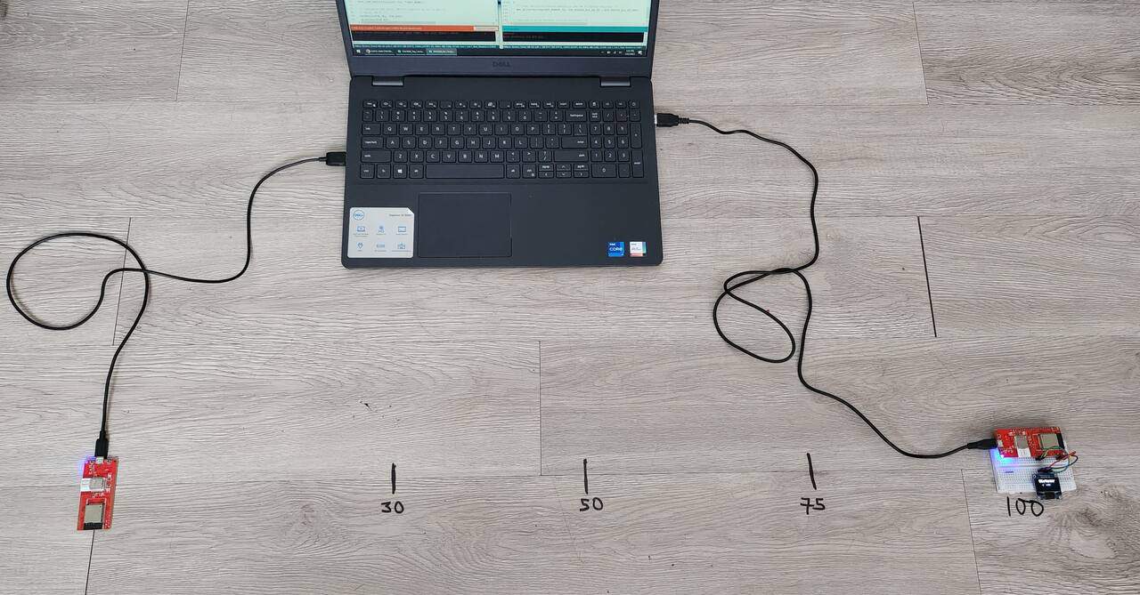
I marked 1 meter distance and between the I marked positions as 30cm, 50cm, 75cm, 100cm. Now the device is ready for testing.
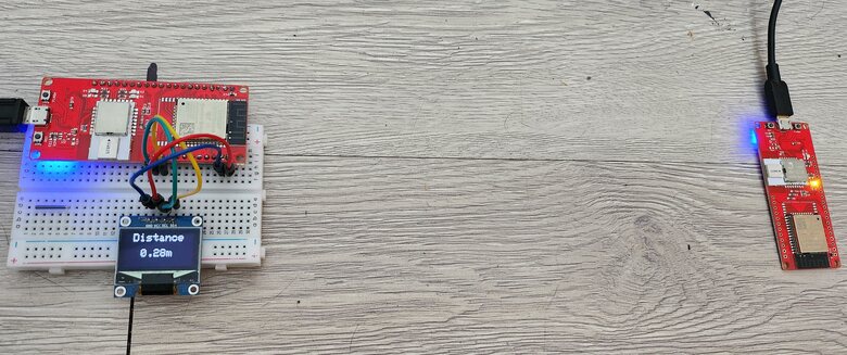
At 30cm, it shows a distance of 28cm.
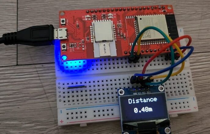
At 50cm, it shows a distance of 48cm.
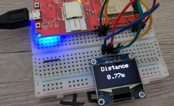
On increasing the distance to 75cm, it shows a distance of 77cm.
Finally for a 100cm distance it shows a distance of 107cm.
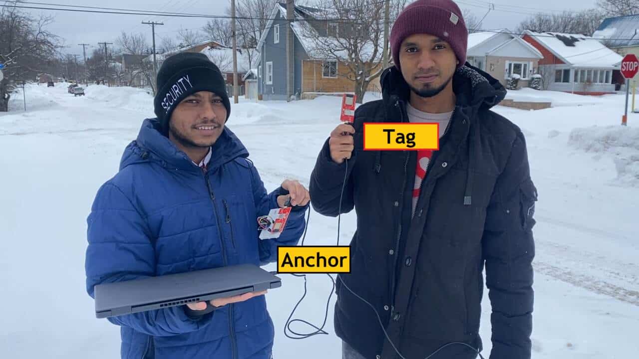
But it still requires a distance test of 10 meters or more. So, I went outdoors to test the distances. Currently, it’s the snowy season in Canada. Despite I need to do the testing. I have my two friends with me who will help me test this product even in such cold snowy weather. One of the friends has Tag on his hand and he is powering the ESP32 UWB Module using the power bank. The other friend has Anchor which is powered by a laptop.
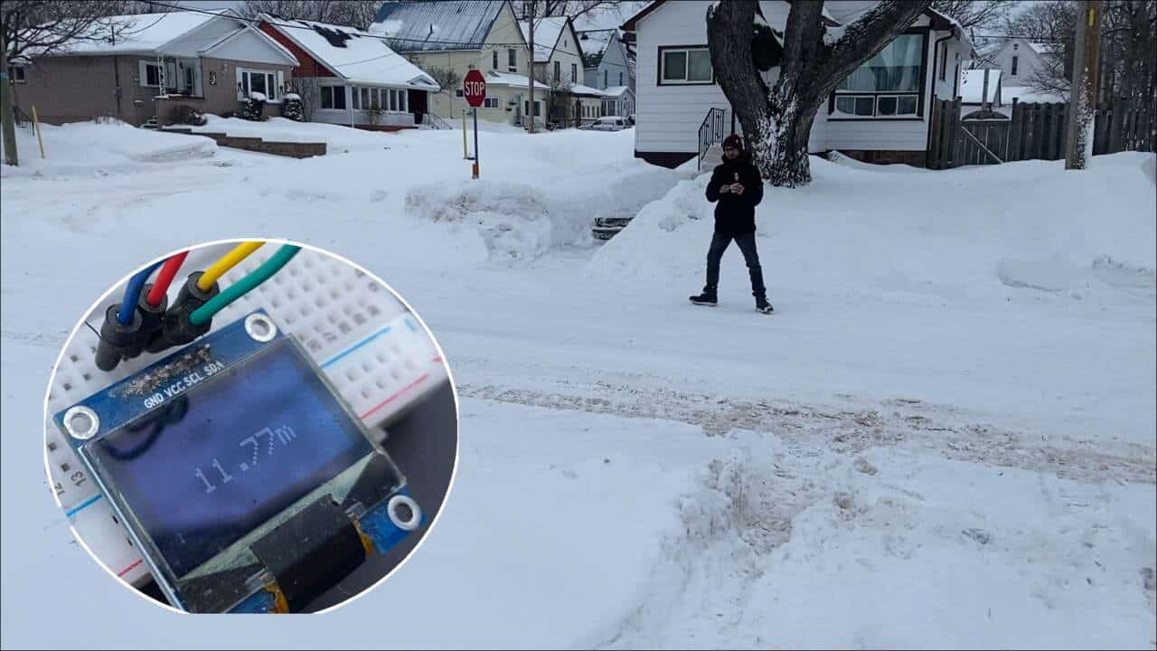
When the tag is nearby the detected distance was almost 2 meters. While moving away, the detected distance was almost 11.77 meters.
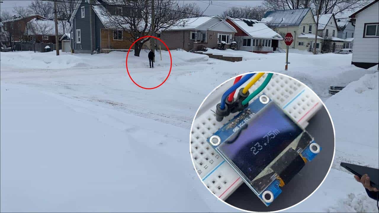
On moving further to a longer distance, the OLED shows a distance of 23.75 meters. Then it stopped receiving signals. So as far as our test the maximum distance detected was almost 24 meters which is more than the maximum measuring ability of 20 meters.
Overall, we were satisfied with the working and accuracy of the DW3000 UWB Module. Hence, we can say you can use this module for High Accuracy Localization and testing. The ESP32 DW3000 UWB Board also interpolates with the Apple chip, which also requires testing.
Video Tutorial & Guide


10 Comments
Is it possible to scan and measure the distance to a Iphone or Apples Airtag? If yes, can you please provide a code for that?
Is it also compatible to Qorvos Nearby Interaction” iOS App?
I am having trouble adding the dw3000 zip file from maker fabs website. When I add zip into library I get this error. “Error: 13 INTERNAL: Library install failed: moving extracted archive to destination dir: library not valid” Can anyone help?
Hi,
From inside the folder “Makerfabs-ESP32-UWB-DW3000-main”, you have to copy only the subfolder “Dw3000” to YOUR subfolder ../Arduino/libraries
So you will have a new folder : ../Arduino/libraries/Dw3000
regards,
Jean
Hi,
I’m using two of your modules with the range example and very often the distance information will not be updated for seconds. Has anybody the same behavior? How can I fix this?
Second question: Is it possible to change the communication to 10Hz?
Right now I’ve only changed the parameter: RNG_DELAY_MS to 100.
Do I need to change further parameters such as POLL_RX_TO_RESP_TX_DLY_UUS for example?
Thanks!
I am looking for a sample tdoa code but I couldn’t find it. How can I find a sample code for TDoA?
Is it possible to mix DW1000 and DW3000 devices in the same application? Say two DW3000 as anchors and two DW1000 devices as tags? Thanks
Just go to github (https://github.com/Makerfabs/Makerfabs-ESP32-UWB-DW3000), extract the project somewhere (download it as a zip file), unzip it somewhere, copy the subfolder DW3000 of the extracted zip to your local Arduino “libraries” folder. Dont go the usual Arduino way of “add zip to lib”. At the end, you should have a “DW3000” folder in your arduino libraries folder.
Hi, I have successfully run the Range demo available in DW3000 lib subfolders, but when I use your code for Anchor and Tag, it doesnt work…
I did cut and paste of your source, but seems the boards do not receive uwb frames…
Are you shure the code published on this page work as expected ?
Did anyone use this module for multiple tags and anchors ?
Hi, I am currently busy with an UWB project that requires long range. I see the article mentioning the 500 meters uses different libraries than the first article (DW3000.h).
Is there a way to increase the range using the dw3000.h library?