

Overview
In this guide, we will be using the latest UWB DW3000 Module (Makerfabs MaUWB DW3000) based on ESP32 & STM32 for range testing. This module integrates the MCU and all RF circuits, antennas, power management, and clock circuits. This new UWB module fixes issues between many anchors and tags and can handle up to 8 anchors and 32 tags for creating a system that tracks multiple positions.
In this tutorial, we will learn how we can set up the anchor and tag and use the basic code to establish the communication between Anchor and Tag. The Anchor and Tag will show the distance and RSSI value from each other. According to the manufacturer, it is claimed that the communicating distance that can be achieved by this module is 500 meters. We will therefore do the ESP32 DW3000 UWB Module Range test.
Before moving to the main project part, go through the following posts about the usage of the UWB Module:
- Getting Started with ESP32 DW1000 UWB Module
- ESP32 DW1000 UWB Indoor Location Positioning System
- Ranging & Localization with ESP32 UWB DW3000 Module
- ESP32 UWB Pro – Ultra Wideband Module with Amplifier
Bill of Materials
For this tutorial, we will need a pair of UWB Module which you can purchase from the following links.
| S.N. | Components | Quantity | Purchase Links |
|---|---|---|---|
| 1 | MaUWB_DW3000 Module | 1 | Makerfabs |
| 2 | Type C USB Cable | 1 | Amazon | AliExpress |
MaUWB_DW3000 ESP32 + STM32 Board
Ultra-wideband (UWB) is a wireless communication protocol that uses radio waves for secure, reliable ranging and precision sensing, adding spatial context to wireless devices. However, UWB often faces signal interference problems when multiple anchors and tags are in use.
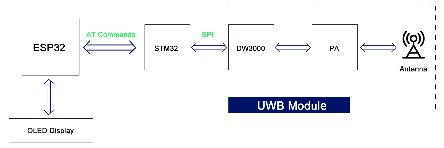
Makerfabs’ latest MaUWB module addresses this issue. It integrates an STM32 controller with default firmware, designed and adjusted for reliability in field applications, to manage the DW3000 multiplexing. This allows the ESP32 controller to easily receive UWB arranging results through simple AT commands.
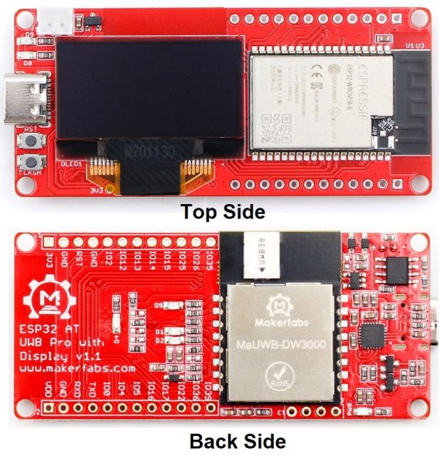
The module combines an MCU, RF circuits, antennas, power management, and clock circuits in one unit. It’s quickly configurable and operable via AT commands. The module supports up to 8 anchors and 32 tags, enabling the creation of a multi-anchor, multi-tag positioning system.
Makerfabs MaUWB make it possible to use UWB tech with any controller easily, with simple AT commands, to create a multi-anchor multi-tag positioning system. You can purchase the product from Makerfabs Official site.
Features
- Comply with IEEE802.15.4-2011 ultra-wideband standard;
- Easy to integrate without additional RF design;
- Support CH5 (6489.6MHZ) RF band;
- Strong resistance to multi-path fading;
- Two modes of data transmission rate of 850kbps and 6.8Mbps;
- The maximum packet length is 1023 bytes, which meets the application requirements of high data volume exchange;
- The system supports 8Anchor32 tags.
- The module supports free configuration of refresh rate, up to 100Hz;
- Module serial port communication baud rate 115200;
- Module (Tag) deep hibernation working current as low as 35uA, working current 34mA;
- Support AT command;
- Board USB supply voltage range: 4.8~5.5V, 5.0V Typical
- Board Battery supply voltage range: 3.4~4.2V, 3.7V Typical
Basic Demo and Test Code
In this example code we will configure ESP32 UWB DW3000 Board with Arduino IDE and install necessaries libraries. In this demo the ESP32 controller can get the UWB arranging result simple by AT commands.
We will use the basic example code to get the distance and signal strength value from Tag0 to Anchor0.
The Board has SSD1306 OLED Display embedded with ESP32 Board. Hence you need to install the Adafruit SSD1306 and Adafruit GFX libraries to the Arduino IDE.
Basic Tag Code
In this code, we will set the board to Tag0.
Use Type-C USB cable to connect the board and PC, and select the development board “ESP32 Dev Module” and the “COM port”.
Verify the code and upload.
|
1 2 3 4 5 6 7 8 9 10 11 12 13 14 15 16 17 18 19 20 21 22 23 24 25 26 27 28 29 30 31 32 33 34 35 36 37 38 39 40 41 42 43 44 45 46 47 48 49 50 51 52 53 54 55 56 57 58 59 60 61 62 63 64 65 66 67 68 69 70 71 72 73 74 75 76 77 78 79 80 81 82 83 84 85 86 87 88 89 90 91 92 93 94 95 96 97 98 99 100 101 102 103 104 105 106 107 108 109 110 111 112 113 114 115 116 117 118 119 120 121 122 123 124 125 126 127 128 129 130 131 132 133 134 135 136 137 138 139 140 141 142 143 144 145 146 147 148 149 150 151 152 153 154 155 156 157 158 159 160 161 162 163 164 165 166 167 168 169 170 171 172 173 174 175 176 177 178 179 180 181 182 183 184 185 186 187 188 189 190 191 192 193 194 195 196 197 198 199 200 201 202 203 204 205 206 207 208 209 210 211 212 213 214 215 216 217 218 |
// User config ------------------------------------------ #define UWB_INDEX 0 #define TAG // #define ANCHOR #define FREQ_850K // #define FREQ_6800K #define UWB_TAG_COUNT 32 // User config end ------------------------------------------ #include <Wire.h> #include <Adafruit_GFX.h> #include <Adafruit_SSD1306.h> #include <Arduino.h> #define SERIAL_LOG Serial #define SERIAL_AT mySerial2 HardwareSerial SERIAL_AT(2); #define RESET 32 #define IO_RXD2 18 #define IO_TXD2 19 #define I2C_SDA 4 #define I2C_SCL 5 Adafruit_SSD1306 display(128, 64, &Wire, -1); void setup() { pinMode(RESET, OUTPUT); digitalWrite(RESET, HIGH); SERIAL_LOG.begin(115200); SERIAL_LOG.print(F("Hello! ESP32-S3 AT command V1.0 Test")); SERIAL_AT.begin(115200, SERIAL_8N1, IO_RXD2, IO_TXD2); SERIAL_AT.println("AT"); Wire.begin(I2C_SDA, I2C_SCL); delay(1000); // SSD1306_SWITCHCAPVCC = generate display voltage from 3.3V internally if (!display.begin(SSD1306_SWITCHCAPVCC, 0x3C)) { // Address 0x3C for 128x32 SERIAL_LOG.println(F("SSD1306 allocation failed")); for (;;) ; // Don't proceed, loop forever } display.clearDisplay(); logoshow(); sendData("AT?", 2000, 1); sendData("AT+RESTORE", 5000, 1); sendData(config_cmd(), 2000, 1); sendData(cap_cmd(), 2000, 1); sendData("AT+SETRPT=1", 2000, 1); sendData("AT+SAVE", 2000, 1); sendData("AT+RESTART", 2000, 1); } long int runtime = 0; String response = ""; String rec_head = "AT+RANGE"; void loop() { // put your main code here, to run repeatedly: while (SERIAL_LOG.available() > 0) { SERIAL_AT.write(SERIAL_LOG.read()); yield(); } while (SERIAL_AT.available() > 0) { char c = SERIAL_AT.read(); if (c == '\r') continue; else if (c == '\n' || c == '\r') { SERIAL_LOG.println(response); response = ""; } else response += c; } } // SSD1306 void logoshow(void) { display.clearDisplay(); display.setTextSize(1); // Normal 1:1 pixel scale display.setTextColor(SSD1306_WHITE); // Draw white text display.setCursor(0, 0); // Start at top-left corner display.println(F("MaUWB DW3000")); display.setCursor(0, 20); // Start at top-left corner // display.println(F("with STM32 AT Command")); display.setTextSize(2); String temp = ""; #ifdef TAG temp = temp + "T" + UWB_INDEX; #endif #ifdef ANCHOR temp = temp + "A" + UWB_INDEX; #endif #ifdef FREQ_850K temp = temp + " 850k"; #endif #ifdef FREQ_6800K temp = temp + " 6.8M"; #endif display.println(temp); display.setCursor(0, 40); temp = "Total: "; temp = temp + UWB_TAG_COUNT; display.println(temp); display.display(); delay(2000); } String sendData(String command, const int timeout, boolean debug) { String response = ""; // command = command + "\r\n"; SERIAL_LOG.println(command); SERIAL_AT.println(command); // send the read character to the SERIAL_LOG long int time = millis(); while ((time + timeout) > millis()) { while (SERIAL_AT.available()) { // The esp has data so display its output to the serial window char c = SERIAL_AT.read(); // read the next character. response += c; } } if (debug) { SERIAL_LOG.println(response); } return response; } String config_cmd() { String temp = "AT+SETCFG="; // Set device id temp = temp + UWB_INDEX; // Set device role #ifdef TAG temp = temp + ",0"; #endif #ifdef ANCHOR temp = temp + ",1"; #endif // Set frequence 850k or 6.8M #ifdef FREQ_850K temp = temp + ",0"; #endif #ifdef FREQ_6800K temp = temp + ",1"; #endif // Set range filter temp = temp + ",1"; return temp; } String cap_cmd() { String temp = "AT+SETCAP="; // Set Tag capacity temp = temp + UWB_TAG_COUNT; // Time of a single time slot #ifdef FREQ_850K temp = temp + ",15"; #endif #ifdef FREQ_6800K temp = temp + ",10"; #endif return temp; } |
Basic Anchor Code
In this code, we will set the board to Anchor0.
Use Type-C USB cable to connect the another board and PC, and select the development board “ESP32 Dev Module” and the “COM port“.
Verify the code and upload.
|
1 2 3 4 5 6 7 8 9 10 11 12 13 14 15 16 17 18 19 20 21 22 23 24 25 26 27 28 29 30 31 32 33 34 35 36 37 38 39 40 41 42 43 44 45 46 47 48 49 50 51 52 53 54 55 56 57 58 59 60 61 62 63 64 65 66 67 68 69 70 71 72 73 74 75 76 77 78 79 80 81 82 83 84 85 86 87 88 89 90 91 92 93 94 95 96 97 98 99 100 101 102 103 104 105 106 107 108 109 110 111 112 113 114 115 116 117 118 119 120 121 122 123 124 125 126 127 128 129 130 131 132 |
#include <Wire.h> #include <Adafruit_GFX.h> #include <Adafruit_SSD1306.h> #include <Arduino.h> #define SERIAL_LOG Serial #define SERIAL_AT mySerial2 HardwareSerial SERIAL_AT(2); #define RESET 32 #define IO_RXD2 18 #define IO_TXD2 19 #define I2C_SDA 4 #define I2C_SCL 5 Adafruit_SSD1306 display(128, 64, &Wire, -1); void setup() { pinMode(RESET, OUTPUT); digitalWrite(RESET, HIGH); SERIAL_LOG.begin(115200); SERIAL_LOG.print(F("Hello! ESP32-S3 AT command V1.0 Test")); SERIAL_AT.begin(115200, SERIAL_8N1, IO_RXD2, IO_TXD2); SERIAL_AT.println("AT"); Wire.begin(I2C_SDA, I2C_SCL); delay(1000); // SSD1306_SWITCHCAPVCC = generate display voltage from 3.3V internally if (!display.begin(SSD1306_SWITCHCAPVCC, 0x3C)) { // Address 0x3C for 128x32 SERIAL_LOG.println(F("SSD1306 allocation failed")); for (;;) ; // Don't proceed, loop forever } display.clearDisplay(); logoshow(); sendData("AT?", 2000, 1); sendData("AT+RESTORE", 5000, 1); sendData("AT+SETCFG=0,1,0,1", 2000, 1); sendData("AT+SETCAP=32,15", 2000, 1); sendData("AT+SETRPT=1", 2000, 1); sendData("AT+SAVE", 2000, 1); sendData("AT+RESTART", 2000, 1); } long int runtime = 0; String response = ""; String rec_head = "AT+RANGE"; void loop() { // put your main code here, to run repeatedly: while (SERIAL_LOG.available() > 0) { SERIAL_AT.write(SERIAL_LOG.read()); yield(); } while (SERIAL_AT.available() > 0) { char c = SERIAL_AT.read(); if (c == '\r') continue; else if (c == '\n' || c == '\r') { SERIAL_LOG.println(response); response = ""; } else response += c; } } // SSD1306 void logoshow(void) { display.clearDisplay(); display.setTextSize(1); // Normal 1:1 pixel scale display.setTextColor(SSD1306_WHITE); // Draw white text display.setCursor(0, 0); // Start at top-left corner display.println(F("MaUWB DW3000")); display.setCursor(0, 20); // Start at top-left corner display.println(F("with STM32 AT Command")); display.setTextSize(2); display.setCursor(0, 40); // Start at top-left corner display.println(F("A0")); display.display(); delay(2000); } String sendData(String command, const int timeout, boolean debug) { String response = ""; // command = command + "\r\n"; SERIAL_LOG.println(command); SERIAL_AT.println(command); // send the read character to the SERIAL_LOG long int time = millis(); while ((time + timeout) > millis()) { while (SERIAL_AT.available()) { // The esp has data so display its output to the serial window char c = SERIAL_AT.read(); // read the next character. response += c; } } if (debug) { SERIAL_LOG.println(response); } return response; } |
Results & Testing
After the code is uploaded to both these boards, the device is ready for testing.
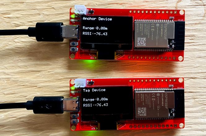
The OLED on both the board will display some messages as shown in the image below.
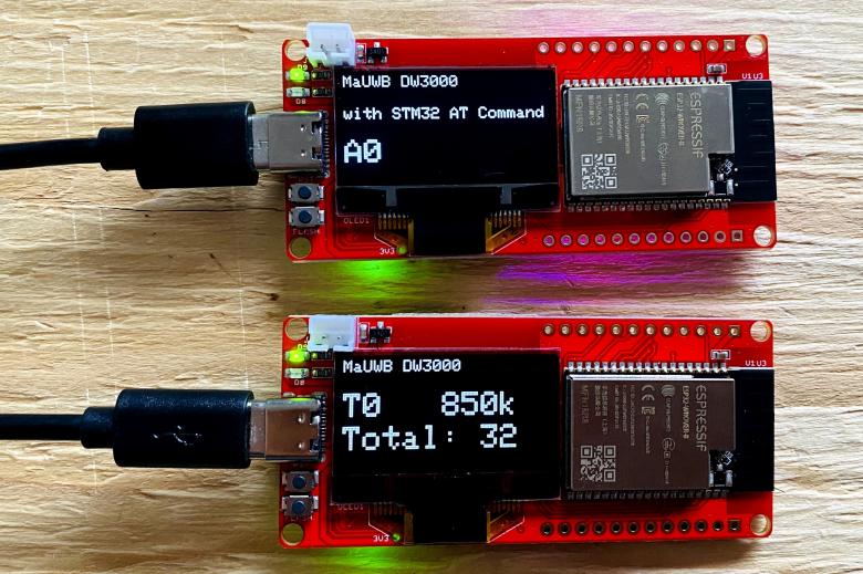
Here one of the board is set as Anchor0 and other board as Tag0.
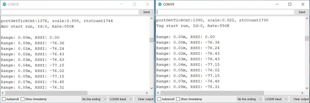
Now you can open the Serial Monitor on any of the COM Port. The Serial Monitor will show the distance and RSSI values.
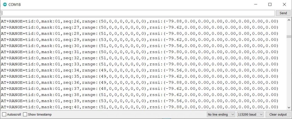
In this image you can see the distance appears to be between 48 to 51 which is in centimeters. Similarly the RSSI value appears to be as -79 or -80.
ESP32 DW3000 UWB Module Range Testing
The above test code is written for reading the distance and RSSI from 8 tags. The distance and RSSI value is displayed on Serial Monitor.
The code need to be modified to only display the RSSI and Distance value of single anchor and a single tag. Apart from this modification, we also want to display the RSSI and Distance Value on OLED Screen. This is useful in case if you wanna do the outdoor range testing.
Modified Tag Code
Here is the modified Tag code that displays the distance and RSSI value on OLED Display.
|
1 2 3 4 5 6 7 8 9 10 11 12 13 14 15 16 17 18 19 20 21 22 23 24 25 26 27 28 29 30 31 32 33 34 35 36 37 38 39 40 41 42 43 44 45 46 47 48 49 50 51 52 53 54 55 56 57 58 59 60 61 62 63 64 65 66 67 68 69 70 71 72 73 74 75 76 77 78 79 80 81 82 83 84 85 86 87 88 89 90 91 92 93 94 95 96 97 98 99 100 101 102 103 104 105 106 107 108 109 110 111 112 113 114 115 116 117 118 119 120 121 122 123 124 125 126 127 128 129 130 131 132 133 134 135 136 137 138 139 140 141 142 143 144 145 146 147 148 149 150 151 152 153 154 155 156 157 158 159 160 161 162 163 164 165 166 167 168 169 170 171 172 173 174 175 176 177 178 179 180 181 182 183 184 185 186 187 188 189 190 191 192 193 194 195 196 197 198 199 200 201 202 203 204 205 206 207 208 209 |
// Include necessary libraries #include <Wire.h> #include <Adafruit_GFX.h> #include <Adafruit_SSD1306.h> #include <Arduino.h> // Configuration settings #define UWB_INDEX 0 #define TAG // #define ANCHOR #define FREQ_850K // #define FREQ_6800K #define UWB_TAG_COUNT 32 // Define serial connections #define SERIAL_LOG Serial #define SERIAL_AT mySerial2 HardwareSerial SERIAL_AT(2); // Define pin assignments #define RESET 32 #define IO_RXD2 18 #define IO_TXD2 19 #define I2C_SDA 4 #define I2C_SCL 5 Adafruit_SSD1306 display(128, 64, &Wire, -1); // Initialize global variables long int runtime = 0; String response = ""; String rec_head = "AT+RANGE"; // Setup function runs once at startup void setup() { pinMode(RESET, OUTPUT); // Set RESET pin as output digitalWrite(RESET, HIGH); // Initialize RESET to high // Initialize serial connections SERIAL_LOG.begin(115200); // Start SERIAL_LOG at 115200 baud SERIAL_AT.begin(115200, SERIAL_8N1, IO_RXD2, IO_TXD2); // Start SERIAL_AT SERIAL_AT.println("AT"); // Send AT command to initiate communication Wire.begin(I2C_SDA, I2C_SCL); delay(1000); // SSD1306_SWITCHCAPVCC = generate display voltage from 3.3V internally if (!display.begin(SSD1306_SWITCHCAPVCC, 0x3C)) { // Address 0x3C for 128x32 SERIAL_LOG.println(F("SSD1306 allocation failed")); for (;;) ; // Don't proceed, loop forever } display.clearDisplay(); // Send initial configuration AT commands sendData("AT?", 2000, 1); sendData("AT+RESTORE", 5000, 1); sendData(config_cmd(), 2000, 1); sendData(cap_cmd(), 2000, 1); sendData("AT+SETRPT=1", 2000, 1); sendData("AT+SAVE", 2000, 1); sendData("AT+RESTART", 2000, 1); } // Main loop function runs repeatedly after setup void loop() { // Check for data from SERIAL_AT and process it while (SERIAL_AT.available() > 0) { char c = SERIAL_AT.read(); // Read next character if (c == '\r') continue; // Ignore carriage return else if (c == '\n' || c == '\r') { processRangeResponse(response); // Process range response response = ""; // Clear response string for next message } else { response += c; // Append character to response } } } // Function to process AT+RANGE responses void processRangeResponse(String response) { if (response.startsWith("AT+RANGE")) { // Extract range value int rangeStart = response.indexOf("range:(") + 7; int rangeEnd = response.indexOf(',', rangeStart); String rangeStr = response.substring(rangeStart, rangeEnd); float range = rangeStr.toFloat(); // Convert the range string to a float // Convert range from cm to m by dividing by 100 range /= 100.0; // Extract RSSI value int rssiStart = response.indexOf("rssi:(") + 6; int rssiEnd = response.indexOf(',', rssiStart); String rssi = response.substring(rssiStart, rssiEnd); // Print the range and RSSI values to Serial Monitor SERIAL_LOG.print("Range: "); SERIAL_LOG.print(range); // This will print the range in meters SERIAL_LOG.print("m, RSSI: "); SERIAL_LOG.println(rssi); // Update OLED display display.clearDisplay(); display.setTextColor(WHITE); display.setTextSize(1); display.setCursor(0, 0); display.print("Tag Device"); display.setCursor(0, 25); display.print("Range:"); display.print(range); // This will display the range in meters display.print("m"); display.setCursor(0, 40); display.print("RSSI:"); display.print(rssi); display.display(); } } // Function to send AT commands and return the response String sendData(String command, const int timeout, boolean debug) { String response = ""; // Local variable to store the response SERIAL_LOG.println(command); // Print command to Serial Monitor SERIAL_AT.println(command); // Send command over serial long int time = millis(); // Capture the current time // Wait for a response or until timeout while ((time + timeout) > millis()) { while (SERIAL_AT.available()) { char c = SERIAL_AT.read(); // Read next character response += c; // Append character to response string } } if (debug) { SERIAL_LOG.println(response); // Print response if debugging is enabled } return response; // Return the response } // Function to generate AT+SETCFG command String config_cmd() { String temp = "AT+SETCFG="; temp += UWB_INDEX; // Add device ID to the command // Add device role to the command #ifdef TAG temp += ",0"; #endif #ifdef ANCHOR temp += ",1"; #endif // Add frequency to the command #ifdef FREQ_850K temp += ",0"; #endif #ifdef FREQ_6800K temp += ",1"; #endif temp += ",1"; // Add range filter setting return temp; // Return the command } // Function to generate AT+SETCAP command String cap_cmd() { String temp = "AT+SETCAP="; temp += UWB_TAG_COUNT; // Add Tag capacity to the command // Add time slot duration based on frequency #ifdef FREQ_850K temp += ",15"; #endif #ifdef FREQ_6800K temp += ",10"; #endif return temp; // Return the command } |
Modified Anchor Code
Here is the modified anchor code that displays the distance and RSSI value on OLED Display.
|
1 2 3 4 5 6 7 8 9 10 11 12 13 14 15 16 17 18 19 20 21 22 23 24 25 26 27 28 29 30 31 32 33 34 35 36 37 38 39 40 41 42 43 44 45 46 47 48 49 50 51 52 53 54 55 56 57 58 59 60 61 62 63 64 65 66 67 68 69 70 71 72 73 74 75 76 77 78 79 80 81 82 83 84 85 86 87 88 89 90 91 92 93 94 95 96 97 98 99 100 101 102 103 104 105 106 107 108 109 110 111 112 113 114 115 116 117 118 119 120 121 122 123 124 125 126 127 128 129 130 131 132 133 134 135 136 137 138 139 140 141 142 143 144 145 146 147 148 149 150 151 152 153 154 155 156 157 158 159 160 161 162 163 |
#include <Wire.h> #include <Adafruit_GFX.h> #include <Adafruit_SSD1306.h> #include <Arduino.h> // Define serial connections #define SERIAL_LOG Serial #define SERIAL_AT mySerial2 HardwareSerial SERIAL_AT(2); // Define pin assignments #define RESET 32 #define IO_RXD2 18 #define IO_TXD2 19 #define I2C_SDA 4 #define I2C_SCL 5 Adafruit_SSD1306 display(128, 64, &Wire, -1); // Initialize global variables long int runtime = 0; String response = ""; String rec_head = "AT+RANGE"; // Setup function runs once at startup void setup() { pinMode(RESET, OUTPUT); // Set RESET pin as output digitalWrite(RESET, HIGH); // Initialize RESET to high // Initialize serial connections SERIAL_LOG.begin(115200); // Start SERIAL_LOG at 115200 baud SERIAL_AT.begin(115200, SERIAL_8N1, IO_RXD2, IO_TXD2); // Start SERIAL_AT SERIAL_AT.println("AT"); // Send AT command to initiate communication Wire.begin(I2C_SDA, I2C_SCL); delay(1000); // SSD1306_SWITCHCAPVCC = generate display voltage from 3.3V internally if (!display.begin(SSD1306_SWITCHCAPVCC, 0x3C)) { // Address 0x3C for 128x32 SERIAL_LOG.println(F("SSD1306 allocation failed")); for (;;) ; // Don't proceed, loop forever } display.clearDisplay(); // Send initial configuration AT commands sendData("AT?", 2000, 1); sendData("AT+RESTORE", 5000, 1); sendData("AT+SETCFG=0,1,0,1", 2000, 1); sendData("AT+SETCAP=32,15", 2000, 1); sendData("AT+SETRPT=1", 2000, 1); sendData("AT+SAVE", 2000, 1); sendData("AT+RESTART", 2000, 1); } // Main loop function runs repeatedly after setup void loop() { // Check if there is data on SERIAL_LOG while (SERIAL_LOG.available() > 0) { SERIAL_AT.write(SERIAL_LOG.read()); // Forward data to SERIAL_AT yield(); // Yield to maintain UWB functionality (if applicable) } // Check if there is data from SERIAL_AT while (SERIAL_AT.available() > 0) { char c = SERIAL_AT.read(); // Read next character if (c == '\r') continue; // Ignore carriage return else if (c == '\n' || c == '\r') { processRangeResponse(response); // Process range response response = ""; // Clear response string for next message } else { response += c; // Append character to response } } } // Function to send AT commands String sendData(String command, const int timeout, boolean debug) { String response = ""; // Local variable to store the response // Print command to both Serial Monitors SERIAL_LOG.println(command); SERIAL_AT.println(command); // Send the command over the serial long int time = millis(); // Capture the current time // Wait for a response or until timeout while ((time + timeout) > millis()) { while (SERIAL_AT.available()) { char c = SERIAL_AT.read(); // Read the next character response += c; // Append character to response string } } // If debugging is enabled, print the response if (debug) { SERIAL_LOG.println(response); } return response; // Return the response } // Function to process AT+RANGE responses void processRangeResponse(String response) { // Check if the response starts with AT+RANGE if (response.startsWith("AT+RANGE")) { // Extract range value int rangeStart = response.indexOf("range:(") + 7; int rangeEnd = response.indexOf(',', rangeStart); String rangeStr = response.substring(rangeStart, rangeEnd); float range = rangeStr.toFloat(); // Convert the range string to a float // Convert range from cm to m by dividing by 100 range /= 100.0; // Extract RSSI value int rssiStart = response.indexOf("rssi:(") + 6; int rssiEnd = response.indexOf(',', rssiStart); String rssi = response.substring(rssiStart, rssiEnd); // Print the range and RSSI values to Serial Monitor SERIAL_LOG.print("Range: "); SERIAL_LOG.print(range); // This will print the range in meters SERIAL_LOG.print("m, RSSI: "); SERIAL_LOG.println(rssi); // Update OLED display display.clearDisplay(); display.setTextColor(WHITE); display.setTextSize(1); display.setCursor(0, 0); display.print("Anchor Device"); display.setCursor(0, 25); display.print("Range:"); display.print(range); // This will display the range in meters display.print("m"); display.setCursor(0, 40); display.print("RSSI:"); display.print(rssi); display.display(); } } |
After uploading the code to both Anchor and Tag, the OLED will start displaying the Distance and RSSI value.
The Serial Monitor will also display the value of RSSI and Distance in case of both the Anchor and Tag.
According to the manufacturer the precision is 0.5M in the range 100 meters.
ESP32 DW3000 UWB Range Test
The manufacturer claimed that the UWB Module could achieve a point-to-point distance of 500 meters, so we decided to test this outdoors. To conduct the test in Canada, we needed to avoid rainy and snowy weather, so we tested the range in dry conditions at a temperature of nearly 0 degrees.
One of my friends, carrying the Tag device powered by a 3.7V Lithium-ion battery, walked away from me on a road, holding the device in his hand.
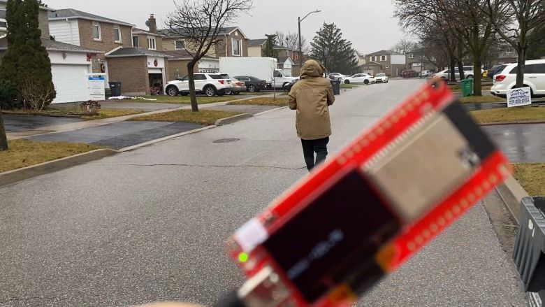
For accurate testing, it’s essential to have an open space with no obstacles between the anchor and the tag.
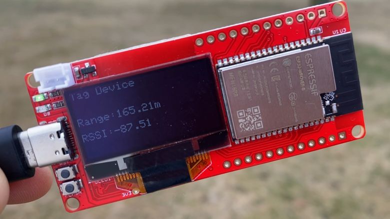
At a distance of 165 meters, the RSSI (Received Signal Strength Indicator) recorded was -87.
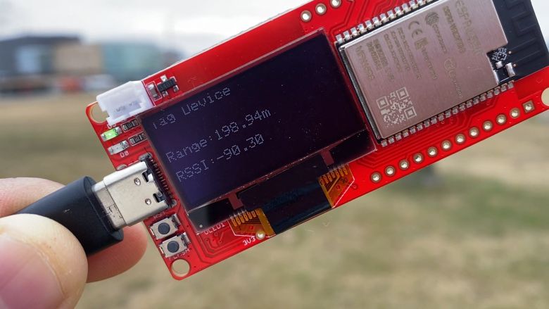
As he moved further to 200 meters, the RSSI dropped to -90.
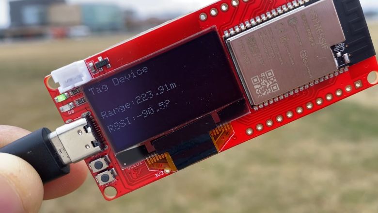
At 224 meters, the RSSI remained at -90.
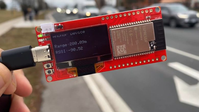
Even at 280 meters, the RSSI was consistent at -90.
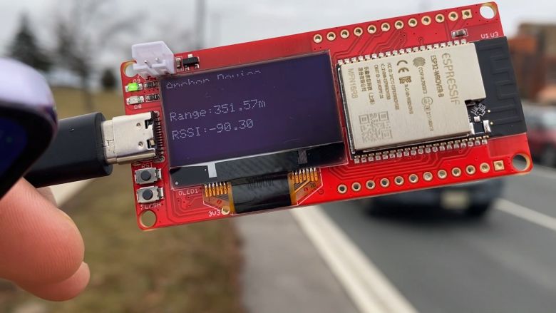
At 351 meters, there was no change in the RSSI.
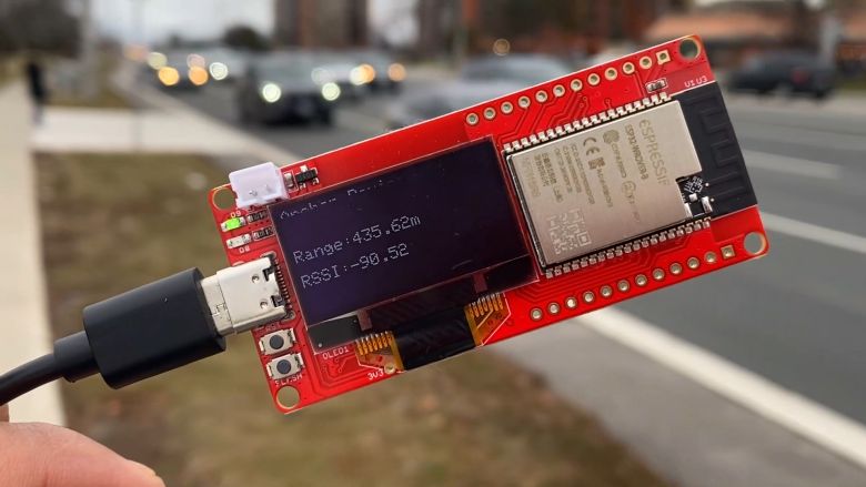
However, once the distance exceeded 400 meters, the signal reception became sporadic, and the RSSI started to fluctuate significantly.
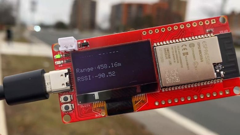
We continued to receive the signal up to a distance of 458 meters.
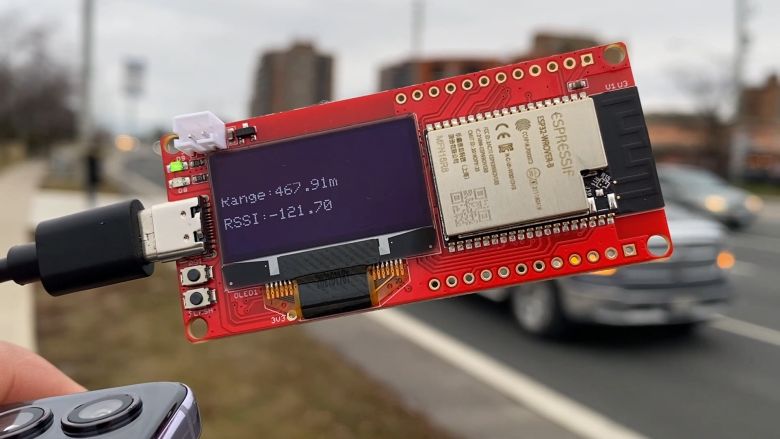
Finally, at 480 meters, the RSSI was recorded at -121.70, and we could barely receive the signal.
During the testing, we observed that the UWB Antenna is not omnidirectional but rather a directional antenna with a 4.16dBi value. Therefore, it’s important to align the antenna of the anchor to face the antenna of the Tag for optimal results.
It was also observed that obstacles such as trees and electric poles affect the signal. The testing conditions in urban areas and open spaces, like farms, yield different maximum ranges. In agricultural farms or open spaces, the range achieved could exceed 600 meters. Additionally, it is advisable to place the DW3000 UWB Tag and Anchor at a height of more than 4-5 feet for better range.
Video Tutorial & Guide


1 Comment
Thank you very much for this.