

Overview
In this comprehensive guide, we will explore Ultra Wideband Technology using the ESP32 UWB Pro Module. This module is equipped with a DW1000 UWB Chip, as well as a Power Amplifier Chip. Although the DW1000 UWB Chip has a native detection range of approximately 40 meters, the addition of the Amplifier chip allows for an extended detection distance of up to 200 meters.
Ultra Wideband (UWB) is a short-range wireless communication protocol that relies on radio waves for secure, reliable ranging and precision sensing, providing an enhanced spatial context for wireless devices.
Throughout this tutorial, we will examine the board design, specifications, and various applications of the ESP32 UWB Pro Module. Additionally, we will learn how to utilize this board for high-accuracy ranging and localization, including distance testing.
To gain a more comprehensive understanding of UWB Technology, we recommend reviewing our previous articles related to the DW1000 Chip and DW3000 Chip before proceeding with this tutorial:
- Getting Started with ESP32 DW1000 UWB Module
- ESP32 DW1000 UWB Indoor Location Positioning System
- Ranging & Localization with ESP32 UWB DW3000 Module
- ESP32 DW3000 UWB Module Achieving 500m Range
Bill of Materials
We need the following components for this project. You can purchase the components from the given links.
| S.N. | Components | Quantity | Purchase Links |
|---|---|---|---|
| 1 | ESP32 UWB Pro Board | 2 | Makerfabs |
| 2 | ESP32 UWB Pro Board with Display | 2 | Makerfabs |
| 3 | Type C USB Cable | 2 | Amazon | AliExpress |
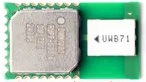
ESP32 DW1000 UWB(Ultra Wideband) Pro Board
Ultra-wideband (UWB) is a short-range, wireless communication protocol that operates through radio waves, and enables secure reliable ranging and precision sensing, creating a new dimension of spatial context for wireless devices.

The ESP32 DW1000 UWB(Ultra Wideband) Pro Board is manufactured by Makerfabs. It uses a DW1000 UWB Pro Chip for Ultra Wideband Communication.
In particular, the ESP32 UWB and UWB DW3000, which offer a maximum distance of 40 meters, may not be sufficient for certain outdoor positioning or large storage positioning applications. To address this challenge, a high-power version of the UWB transceiver has been developed after extensive testing.
With the high-power version, the maximum distance that can be achieved is up to 200 meters. This increased range makes it more suitable for applications where longer distances are required, such as outdoor positioning or large storage facility positioning. This development showcases the versatility of UWB technology and its potential to cater to a wide range of wireless communication requirements.
features of DW1000 UWB Pro
The Key features of the DW1000 UWB Pro include:
- UWB technology: The DW1000 uses UWB technology, which operates in the 3.5-6.5 GHz frequency range, allowing for high-precision, low-power communication.
- Precision: The chip can achieve centimeter-level accuracy in positioning and ranging by measuring the time it takes for a signal to travel between the transmitter and receiver.
- Data rates: The DW1000 supports multiple data rates, including 110 kbps, 850 kbps, and 6.8 Mbps.
- Channel support: The device supports 6 different channels, allowing for more flexibility in system design and operation.
- Low power consumption: The DW1000 is designed for low power consumption, making it suitable for battery-powered devices and energy-efficient systems.
- Integration: The chip can be easily integrated into various devices and systems, including IoT devices, robotics, and industrial automation.
- Security: The DW1000 has built-in security features, such as data encryption and secure-ranging protocols, to ensure secure communication.
- Scalability: The UWB technology used in the DW1000 allows for the development of large-scale networks with thousands of nodes.
Key features of ESP32 UWB Pro Board
- ESP32 for fast & powerful applications
- Support Wifi, Bluetooth
- Arduino IDE Compatible
- Type C USB connector
- Board USB supply voltage range: 4.8~5.5V, 5.0V Typical
- On-board OLED, 1.3” 128*64, so the distance results can be directly displayed
- Lipo battery charger& connector, so this module can work separately with batteries
- Update UWB position, so the module can be directly installed into a case
Range of DW1000 UWB Pro
The range of the Decawave DW1000 UWB transceiver depends on various factors such as the environment, antenna design, and device settings. However, under typical operating conditions, the DW1000 can achieve a line-of-sight communication range of up to 290 meters (approximately 950 feet). This range can be affected by factors such as signal strength, interference, and obstacles in the communication path.

It is essential to optimize antenna design, device settings, and environmental factors to achieve the desired range for specific applications.
Source Code/Program & Library
Let us see the code for ESP32 UWB Pro Module with display. The ESP32 UWB Pro has DW1000 Chip with an amplifier. Hence it requires a modified DW1000 Library. Apart from the DW1000 library, it also requires the library for OLED Display.
After installing the library, we need to upload the code to the pair of ESP32 UWB Pro Module. One of the modules will act as an Anchor and the other one as a Tag.
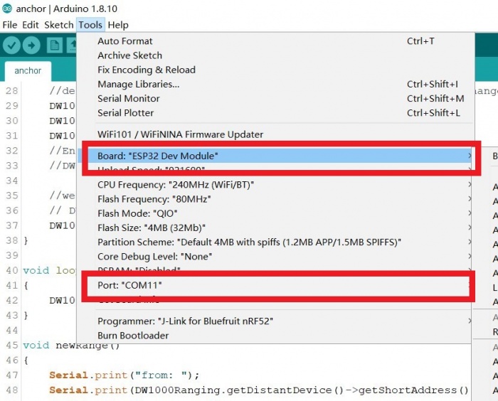
Prepare the module and connect it to the PC with a Type-C cable. Select the development board “ESP32 Dev Module” and the port.
Anchor Code
Upload the following sketch to the ESP32 UWB Pro board. This module can be an anchor port to receive the other UWB device signal.
|
1 2 3 4 5 6 7 8 9 10 11 12 13 14 15 16 17 18 19 20 21 22 23 24 25 26 27 28 29 30 31 32 33 34 35 36 37 38 39 40 41 42 43 44 45 46 47 48 49 50 51 52 53 54 55 56 57 58 59 60 61 62 63 64 65 66 67 68 69 70 71 72 73 74 75 76 77 78 79 80 81 82 83 84 85 86 87 88 89 90 91 92 93 94 95 |
#include <SPI.h> #include "DW1000Ranging.h" #include <Wire.h> #include <Adafruit_GFX.h> #include <Adafruit_SSD1306.h> #define ANCHOR_ADD "86:17:5B:D5:A9:9A:E2:9C" #define SPI_SCK 18 #define SPI_MISO 19 #define SPI_MOSI 23 #define UWB_RST 27 // reset pin #define UWB_IRQ 34 // irq pin #define UWB_SS 21 // spi select pin #define I2C_SDA 4 #define I2C_SCL 5 Adafruit_SSD1306 display(128, 64, &Wire, -1); void setup() { Serial.begin(115200); Wire.begin(I2C_SDA, I2C_SCL); delay(1000); // SSD1306_SWITCHCAPVCC = generate display voltage from 3.3V internally if (!display.begin(SSD1306_SWITCHCAPVCC, 0x3C)) { // Address 0x3C for 128x32 Serial.println(F("SSD1306 allocation failed")); for (;;) ; // Don't proceed, loop forever } display.clearDisplay(); logoshow(); // init the configuration SPI.begin(SPI_SCK, SPI_MISO, SPI_MOSI); DW1000Ranging.initCommunication(UWB_RST, UWB_SS, UWB_IRQ); // Reset, CS, IRQ pin DW1000Ranging.attachNewRange(newRange); DW1000Ranging.attachBlinkDevice(newBlink); DW1000Ranging.attachInactiveDevice(inactiveDevice); DW1000Ranging.startAsAnchor(ANCHOR_ADD, DW1000.MODE_LONGDATA_RANGE_LOWPOWER, false); } void loop() { DW1000Ranging.loop(); } void newRange() { Serial.print("from: "); Serial.print(DW1000Ranging.getDistantDevice()->getShortAddress(), HEX); Serial.print("\t Range: "); Serial.print(DW1000Ranging.getDistantDevice()->getRange()); Serial.print(" m"); Serial.print("\t RX power: "); Serial.print(DW1000Ranging.getDistantDevice()->getRXPower()); Serial.println(" dBm"); } void newBlink(DW1000Device *device) { Serial.print("blink; 1 device added ! -> "); Serial.print(" short:"); Serial.println(device->getShortAddress(), HEX); } void inactiveDevice(DW1000Device *device) { Serial.print("delete inactive device: "); Serial.println(device->getShortAddress(), HEX); } void logoshow(void) { display.clearDisplay(); display.setTextSize(2); // Normal 1:1 pixel scale display.setTextColor(SSD1306_WHITE); // Draw white text display.setCursor(0, 0); // Start at top-left corner display.println(F("Makerfabs")); display.println(F("UWB Anchor")); display.setTextSize(1); display.setCursor(0, 40); // Start at top-left corner display.println(ANCHOR_ADD); display.display(); } |
Tag Code
Upload the following sketch to the ESP32 UWB Pro board. This module can be a tag port to send the signal to other UWB Board.
|
1 2 3 4 5 6 7 8 9 10 11 12 13 14 15 16 17 18 19 20 21 22 23 24 25 26 27 28 29 30 31 32 33 34 35 36 37 38 39 40 41 42 43 44 45 46 47 48 49 50 51 52 53 54 55 56 57 58 59 60 61 62 63 64 65 66 67 68 69 70 71 72 73 74 75 76 77 78 79 80 81 82 83 84 85 86 87 88 89 90 91 92 93 94 95 96 97 98 99 100 101 102 103 104 105 106 107 108 109 110 111 112 113 114 115 116 117 118 119 120 121 122 123 124 125 126 127 128 129 130 131 132 133 134 135 136 137 138 139 140 141 142 143 144 145 146 147 148 149 150 151 152 153 154 155 156 157 158 159 160 161 162 163 164 165 166 167 168 169 170 171 172 173 174 175 176 177 178 179 180 181 182 183 184 185 186 187 188 189 190 191 192 193 194 195 196 197 198 199 200 201 202 203 204 205 206 207 208 209 210 211 212 213 214 215 216 217 218 219 220 221 222 223 224 225 226 227 228 229 230 231 232 233 234 235 236 237 238 239 240 241 242 243 244 245 246 247 248 249 250 251 252 253 254 255 256 257 258 259 260 261 262 263 264 265 266 267 268 269 270 271 272 273 274 275 276 277 278 279 280 281 282 283 284 285 286 287 288 289 290 291 292 293 294 295 296 297 298 299 300 301 302 303 304 305 306 307 308 309 310 311 312 313 314 315 316 317 318 319 320 |
#include <SPI.h> #include "DW1000Ranging.h" #include <Wire.h> #include <Adafruit_GFX.h> #include <Adafruit_SSD1306.h> #define TAG_ADDR "7D:00:22:EA:82:60:3B:9B" // #define DEBUG #define SPI_SCK 18 #define SPI_MISO 19 #define SPI_MOSI 23 #define UWB_RST 27 // reset pin #define UWB_IRQ 34 // irq pin #define UWB_SS 21 // spi select pin #define I2C_SDA 4 #define I2C_SCL 5 struct Link { uint16_t anchor_addr; float range; float dbm; struct Link *next; }; struct Link *uwb_data; Adafruit_SSD1306 display(128, 64, &Wire, -1); void setup() { Serial.begin(115200); Wire.begin(I2C_SDA, I2C_SCL); delay(1000); // SSD1306_SWITCHCAPVCC = generate display voltage from 3.3V internally if (!display.begin(SSD1306_SWITCHCAPVCC, 0x3C)) { // Address 0x3C for 128x32 Serial.println(F("SSD1306 allocation failed")); for (;;) ; // Don't proceed, loop forever } display.clearDisplay(); logoshow(); // init the configuration SPI.begin(SPI_SCK, SPI_MISO, SPI_MOSI); DW1000Ranging.initCommunication(UWB_RST, UWB_SS, UWB_IRQ); // Reset, CS, IRQ pin // define the sketch as anchor. It will be great to dynamically change the type of module DW1000Ranging.attachNewRange(newRange); DW1000Ranging.attachNewDevice(newDevice); DW1000Ranging.attachInactiveDevice(inactiveDevice); // Enable the filter to smooth the distance // DW1000Ranging.useRangeFilter(true); // we start the module as a tag DW1000Ranging.startAsTag(TAG_ADDR, DW1000.MODE_LONGDATA_RANGE_LOWPOWER); // DW1000Ranging.startAsTag(TAG_ADDR, DW1000.MODE_SHORTDATA_FAST_LOWPOWER); // DW1000Ranging.startAsTag(TAG_ADDR, DW1000.MODE_LONGDATA_FAST_LOWPOWER); // DW1000Ranging.startAsTag(TAG_ADDR, DW1000.MODE_SHORTDATA_FAST_ACCURACY); // DW1000Ranging.startAsTag(TAG_ADDR, DW1000.MODE_LONGDATA_FAST_ACCURACY); // DW1000Ranging.startAsTag(TAG_ADDR, DW1000.MODE_LONGDATA_RANGE_ACCURACY); uwb_data = init_link(); } long int runtime = 0; void loop() { DW1000Ranging.loop(); if ((millis() - runtime) > 1000) { display_uwb(uwb_data); runtime = millis(); } } void newRange() { Serial.print("from: "); Serial.print(DW1000Ranging.getDistantDevice()->getShortAddress(), HEX); Serial.print("\t Range: "); Serial.print(DW1000Ranging.getDistantDevice()->getRange()); Serial.print(" m"); Serial.print("\t RX power: "); Serial.print(DW1000Ranging.getDistantDevice()->getRXPower()); Serial.println(" dBm"); fresh_link(uwb_data, DW1000Ranging.getDistantDevice()->getShortAddress(), DW1000Ranging.getDistantDevice()->getRange(), DW1000Ranging.getDistantDevice()->getRXPower()); // print_link(uwb_data); } void newDevice(DW1000Device *device) { Serial.print("ranging init; 1 device added ! -> "); Serial.print(" short:"); Serial.println(device->getShortAddress(), HEX); add_link(uwb_data, device->getShortAddress()); } void inactiveDevice(DW1000Device *device) { Serial.print("delete inactive device: "); Serial.println(device->getShortAddress(), HEX); delete_link(uwb_data, device->getShortAddress()); } // Data Link struct Link *init_link() { #ifdef DEBUG Serial.println("init_link"); #endif struct Link *p = (struct Link *)malloc(sizeof(struct Link)); p->next = NULL; p->anchor_addr = 0; p->range = 0.0; return p; } void add_link(struct Link *p, uint16_t addr) { #ifdef DEBUG Serial.println("add_link"); #endif struct Link *temp = p; // Find struct Link end while (temp->next != NULL) { temp = temp->next; } Serial.println("add_link:find struct Link end"); // Create a anchor struct Link *a = (struct Link *)malloc(sizeof(struct Link)); a->anchor_addr = addr; a->range = 0.0; a->dbm = 0.0; a->next = NULL; // Add anchor to end of struct Link temp->next = a; return; } struct Link *find_link(struct Link *p, uint16_t addr) { #ifdef DEBUG Serial.println("find_link"); #endif if (addr == 0) { Serial.println("find_link:Input addr is 0"); return NULL; } if (p->next == NULL) { Serial.println("find_link:Link is empty"); return NULL; } struct Link *temp = p; // Find target struct Link or struct Link end while (temp->next != NULL) { temp = temp->next; if (temp->anchor_addr == addr) { // Serial.println("find_link:Find addr"); return temp; } } Serial.println("find_link:Can't find addr"); return NULL; } void fresh_link(struct Link *p, uint16_t addr, float range, float dbm) { #ifdef DEBUG Serial.println("fresh_link"); #endif struct Link *temp = find_link(p, addr); if (temp != NULL) { temp->range = range; temp->dbm = dbm; return; } else { Serial.println("fresh_link:Fresh fail"); return; } } void print_link(struct Link *p) { #ifdef DEBUG Serial.println("print_link"); #endif struct Link *temp = p; while (temp->next != NULL) { // Serial.println("Dev %d:%d m", temp->next->anchor_addr, temp->next->range); Serial.println(temp->next->anchor_addr, HEX); Serial.println(temp->next->range); Serial.println(temp->next->dbm); temp = temp->next; } return; } void delete_link(struct Link *p, uint16_t addr) { #ifdef DEBUG Serial.println("delete_link"); #endif if (addr == 0) return; struct Link *temp = p; while (temp->next != NULL) { if (temp->next->anchor_addr == addr) { struct Link *del = temp->next; temp->next = del->next; free(del); return; } temp = temp->next; } return; } // SSD1306 void logoshow(void) { display.clearDisplay(); display.setTextSize(2); // Normal 1:1 pixel scale display.setTextColor(SSD1306_WHITE); // Draw white text display.setCursor(0, 0); // Start at top-left corner display.println(F("Makerfabs")); display.setTextSize(1); display.setCursor(0, 20); // Start at top-left corner display.println(F("DW1000 DEMO")); display.display(); delay(2000); } void display_uwb(struct Link *p) { struct Link *temp = p; int row = 0; display.clearDisplay(); display.setTextColor(SSD1306_WHITE); if (temp->next == NULL) { display.setTextSize(2); display.setCursor(0, 0); display.println("No Anchor"); display.display(); return; } while (temp->next != NULL) { temp = temp->next; // Serial.println("Dev %d:%d m", temp->next->anchor_addr, temp->next->range); Serial.println(temp->anchor_addr, HEX); Serial.println(temp->range); char c[30]; // sprintf(c, "%X:%.1f m %.1f", temp->anchor_addr, temp->range, temp->dbm); // sprintf(c, "%X:%.1f m", temp->anchor_addr, temp->range); sprintf(c, "%.1f m", temp->range); display.setTextSize(2); display.setCursor(0, row++ * 32); // Start at top-left corner display.println(c); display.println(""); sprintf(c, "%.2f dbm", temp->dbm); display.setTextSize(2); display.println(c); if (row >= 1) { break; } } delay(100); display.display(); return; } |
Demo & Range Testing
Once the code is uploaded on both the anchor and tag board, you can start the testing process. For battery application, I have disabled the OLED code for Anchor Board.

Open the Serial Monitor for both the anchor and tag board.
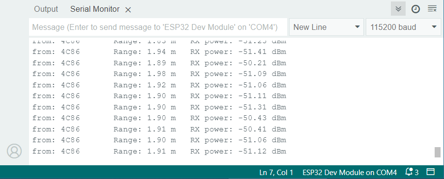
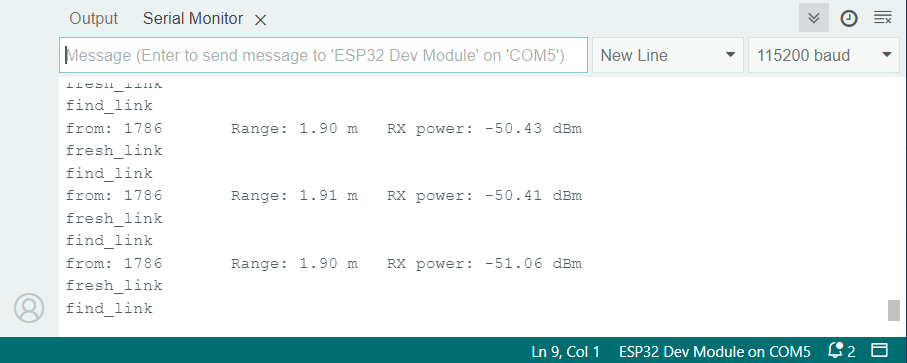
Place the Anchor and Tag board near each other and check the minimum distance.

As this board is designed for long-distance testing, the minimum distance it shows is a little bit incorrect. It showed a distance of 0.5m when it was placed at 0.2m apart. So an additional 300cm distance is shown by it.
Outdoor Range Testing
According to the manufacturer, the range it could offer is 200 meters. So we decided to take it outside for outdoor range testing.
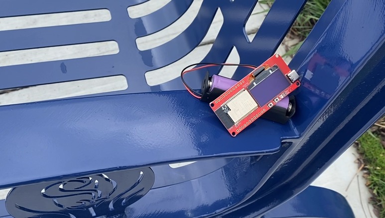
I powered the Anchor using a battery and kept it at stationary position of a bench.

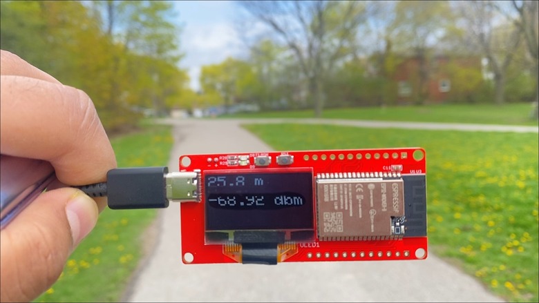
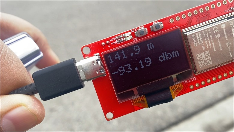
Then the tag was the movable part in this testing. The OLED Display shows measured distance in meters and the signal strength is dbm.
After moving to a certain distance of about 25 meters from the anchor the OLED showed the following distance and signal strength.
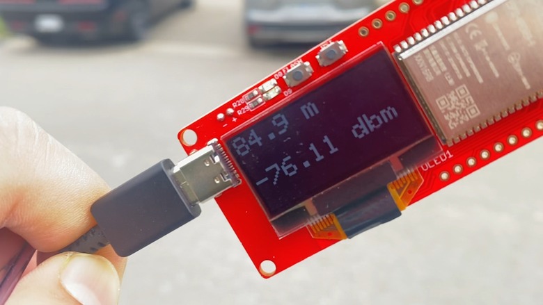
On moving further the OLED kept continuously displaying distance and the signal was proper. But signal strength started decreasing.
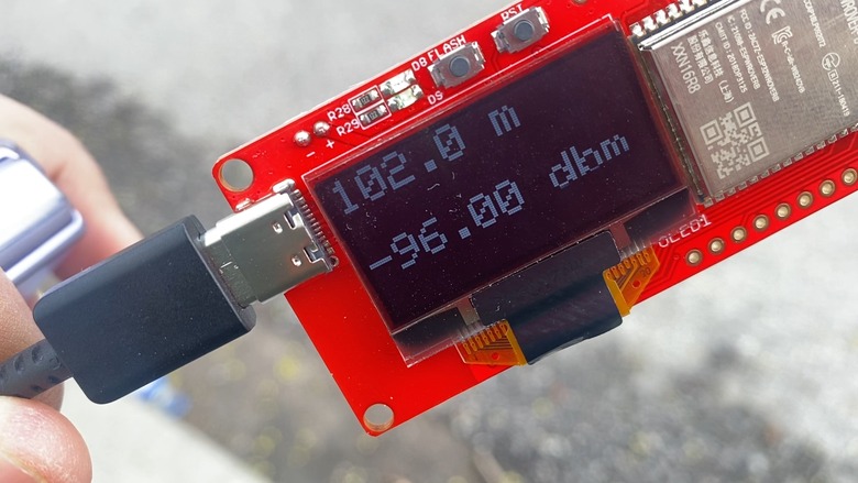
As we reached a 100-meter distance the signal strength further decreased.
Till the distance of 142 meters, the signal was proper and clear.
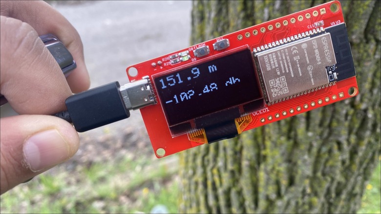
At about 150-meter distance, the signal strength drastically started weakening and sometimes the OLED showed no Anchor as it missed the signal sometimes.
After moving further, the signal was lost and the tag used to receive the signal only sometimes from the Anchor. Most of the time the signal was lost. But we managed to get a distance of 176 meters.

Further we stopped testing as the signal strength was too weak and the tag could rarely receive the signal.
Conclusion
In conclusion, the outdoor range testing of the device revealed that its performance did not meet the manufacturer’s claim of a 200-meter range. This could be because there were obstacles like trees and surrounding was not in proper line of sight while testing. You could do the proper testing again if you wanna get the more distance reading.
The signal was clear and proper up to a distance of 142 meters. However, beyond this point, the signal strength began to weaken significantly, with the connection becoming intermittent at 150 meters. Ultimately, the maximum recorded distance was 176 meters, but the signal was too weak and rarely received by the tag at that point.
Consequently, it is advisable to consider the device’s effective range as less than the advertised 200 meters for practical applications.
Video Tutorial & Guide


