
 Module")
Overview
In this getting started tutorial, we will learn about the Ultra Wideband Technology using ESP32 DW1000 UWB Module. The UWB technology is a wireless carrier communication technology that uses a frequency bandwidth above 1 GHz. It does not use a sinusoidal carrier, but uses nanosecond-level non-sinusoidal narrow pulses to transmit data.
The BU01 is developed by Ai-Thinker based on DecaWave’s DW1000 chip, which integrates an antenna, all RF circuits, power management, and clock modules. ESP32 UWB module based on DW1000 and ESP32 is like a continuously scanning radar that can precisely lock onto another device, discover its location, and communicate with it.
In this tutorial, we will go through the board design, specifications, and applications. Then we will learn how to use the ESP32 DW1000 embedded board for object detection and ranging. During range detection, there might be antenna delay issues leading to measuring incorrect distance. Therefore we will learn the method to fix the distance issue with the Antenna delay calibrating method.
What is Ultra Wideband?
UWB is a short-range, wireless communication protocol similar to Bluetooth or Wi-Fi. It also uses radio waves for communication & operates at a very high frequency. As its name denotes, it also uses a wide spectrum of several GHz. One way to think of it is as a radar that can continuously scan an entire room and precisely lock onto an object like a laser beam to discover its location and communicate data.

The primary purpose of Ultra Wideband is location discovery and device ranging. While both Wi-Fi and Bluetooth have been modified to allow greater accuracy in locating other devices and connecting to them, UWB is natively more precise & uses less power.
How does UWB work?
A UWB transmitter works by sending billions of pulses across the wide spectrum frequency. A corresponding receiver receives the signal, which translates the pulses into data by listening for a familiar pulse sequence sent by the transmitter. Pulses are sent about one every two nanoseconds, which helps UWB achieve its real-time accuracy.

UWB is extremely low power. Its high bandwidth (500MHz) is ideal for relaying a lot of data from a host device to other devices up to about 30 feet away. Unlike Wi-Fi, it is not particularly good at transmitting through walls.
When a smartphone with a UWB chip comes close to another UWB device, the two starts ranging or measuring, their exact distance. The ranging is accomplished through “Time of Flight” (ToF) measurements between the devices. These are used to calculate the roundtrip time of challenge/response packets.
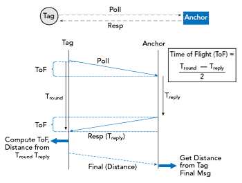
The concepts “anchor” and “tag” are important to understand distance and location measurement with UWB. An anchor is generally a fixed UWB device with a known location. A tag generally refers to a mobile UWB device. An anchor and tag exchange information to establish the distance between them. The exact location of a tag can be determined by communicating with multiple anchors. Some devices can act as either an anchor or tag.
DW1000 Based UWB Module BU01

The BU01 module is developed by Ai-Thinker which is based on DecaWave’s DW1000 chip. It integrates an antenna, all RF circuits, power management, and clock modules. The module can use two-way ranging or TDOA positioning system with a positioning accuracy of 10cm. The data transmission rate of up to 6.8Mbps.
Features
-
Simple integration, no RF design required
-
Using RTLS infrastructure to expand the communication range
-
Support high label density
-
Comply with IEEE 802.15.4-2011 UWB standard
-
Support 4 channels from 3.5 GHz to 6.5 GHz
-
Programmable transmit power
-
Power supply 2.8 V to 3.6 V
-
Power consumption in sleep mode<1mA
-
Support two-way ranging and TDOA
-
Support SPI interface
-
Data rate 110 kbps, 850 kbps, 6.8 Mbps
ESP32 UWB(Ultra Wideband) Board
The ESP32 UWB Ultra Wideband module is based on DW1000 and ESP32. This board is manufactured by Makerfabs. The BU01 Module based on DW1000 Chip is interfaced with ESP32 WiFi Module with I/O expansion. The board acts like a continuously scanning radar, that precisely locks onto another device (called Anchor) and communicates with it, thus calculating its own location.

The top side of the board has ESP32 WROOM/Wrover Module embedded with BU01 Module with other passive electronic components. There are two push buttons, one for flash and the other for rest. The board has a micro-USB port for uploading the firmware and Serial Communication.

On the backside of the board, there is CP2102 Chip for UART communication. The name of the input/output ports is also assigned on the board. The male or female headers can be soldered on both sides of the board. The board is breadboard friendly. Hence you can place it on a breadboard with other components during practical applications.
Features
- Decawave DWM1000 for precision tracking
- ESP32 for fast & powerful applications
- Support Wifi, Bluetooth
- Arduino compatible
- Micro-USB connector
- Board USB supply voltage range: 4.8~5.5V, 5.0V Typical
Getting Started with ESP32 DW1000 UWB (Ultra Wideband) Module
Let’s learn how we can use the ESP32 DW1000 UWB (Ultra Wideband) Board with Arduino IDE and measure the distance between the boards. For this project, you will need pair of boards. Then we need to go through a series of steps to use this Module.
Installing DW1000 Library
First we need to install Arduino-DW1000 Library from thotro. This library offers functionality to use Decawave’s DW1000 chips/modules with Arduino.

You can also install this library through the library manager. Just search for DW1000 and click on install to install the library.
Modifying the Library
The DW1000 UWB library doesn’t compile for ESP32 Boards directly. Therefore we need to make some modifications in the library part.
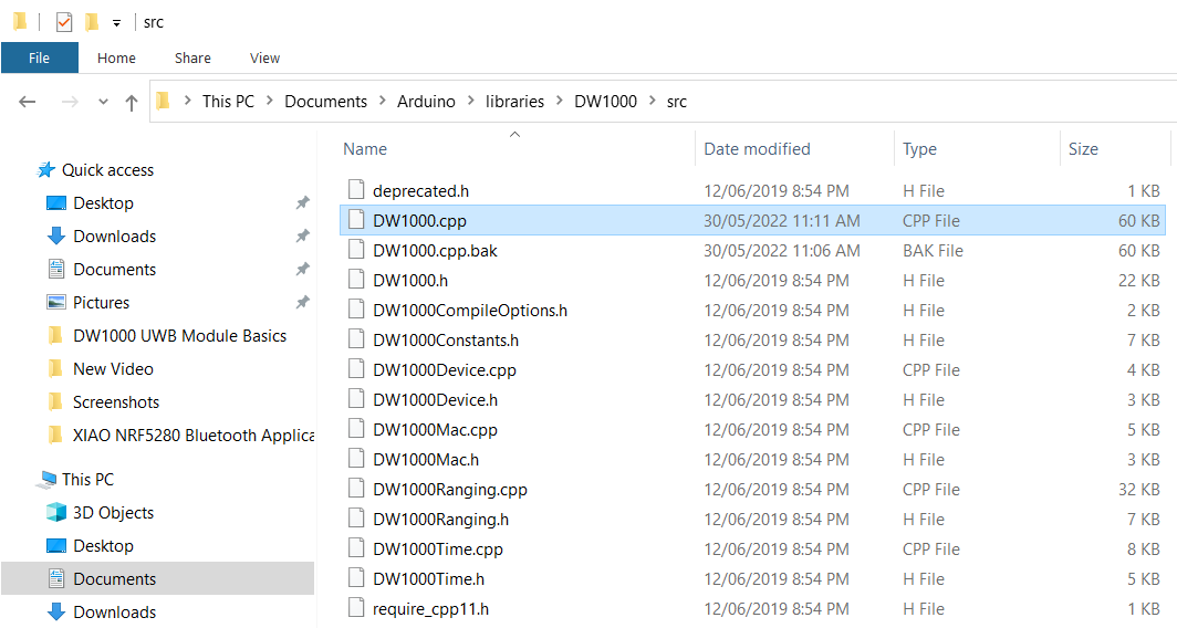
Go to the Arduino Library folder and look for DW1000. Then open the Library folder and look for the source folder (src).

Open the src folder and look for DW1000.cpp file. Open the file with some text editor like Notepad++.
Now look for the following lines (Line No. 172) and comment on all these 3 lines.
|
1 2 3 |
//#ifndef ESP8266 // SPI.usingInterrupt(digitalPinToInterrupt(irq)); // not every board support this, e.g. ESP8266 //#endif |

Once these lines are commented, the library code will successfully compile.
Board Selection
Connect the pair of ESP32 Wrover Board to the two different USB port of your computer with the help of micro-USB Cable.

On your Arduino IDE, select the development board “ESP32 Dev Module” if you are using the ESP32 UWB Board with ESP32 WROOM Chip. Else select the “ESP32 WROVER Module“, if you are using ESP32 UWB Board with ESP32 WROVER Chip.
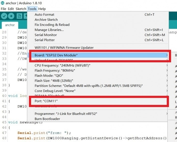
Also select the COM Port. You can find the COM port from the device manager. Now the ESP32 Ultra Wideband Board is ready for Serial Communication.
How to use ESP32 UWB Module to measure the distance?
To measure the distance between the boards, we need to upload an “Anchor” code to one ESP32 Board and the “Tag” code to other ESP32 Board.

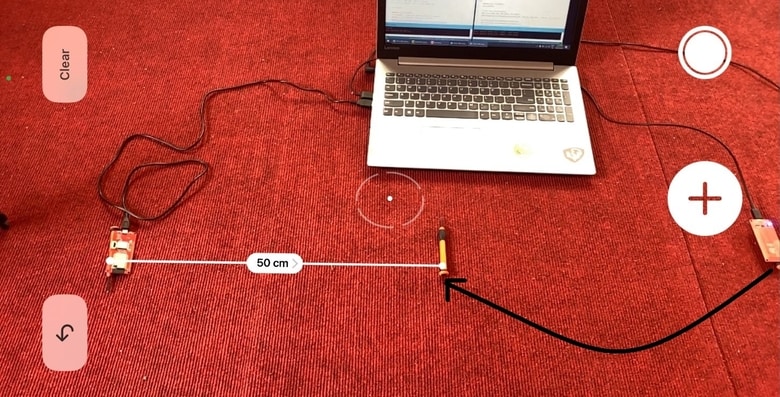
One of the board will act as an Anchor (Sender) and the other board will act as a Tag (Receiver). According to UWB Standards, the Anchor should be stationary and the tag should be movable. For the test purpose, we are keeping the boards at a distance of 1 meter from each other.
Anchor Code
Copy the following code and upload it to the first UWB(Ultra Wideband) Board.
|
1 2 3 4 5 6 7 8 9 10 11 12 13 14 15 16 17 18 19 20 21 22 23 24 25 26 27 28 29 30 31 32 33 34 35 36 37 38 39 40 41 42 43 44 45 46 47 48 49 50 51 52 53 54 55 56 57 58 59 60 61 62 63 64 65 66 67 68 69 |
#include <SPI.h> #include "DW1000Ranging.h" //https://github.com/thotro/arduino-dw1000 #define ANCHOR_ADD "83:17:5B:D5:A9:9A:E2:9C" #define SPI_SCK 18 #define SPI_MISO 19 #define SPI_MOSI 23 #define DW_CS 4 // connection pins const uint8_t PIN_RST = 27; // reset pin const uint8_t PIN_IRQ = 34; // irq pin const uint8_t PIN_SS = 4; // spi select pin void setup() { Serial.begin(115200); delay(1000); //init the configuration SPI.begin(SPI_SCK, SPI_MISO, SPI_MOSI); DW1000Ranging.initCommunication(PIN_RST, PIN_SS, PIN_IRQ); //Reset, CS, IRQ pin //define the sketch as anchor. It will be great to dynamically change the type of module DW1000Ranging.attachNewRange(newRange); DW1000Ranging.attachBlinkDevice(newBlink); DW1000Ranging.attachInactiveDevice(inactiveDevice); //Enable the filter to smooth the distance //DW1000Ranging.useRangeFilter(true); //we start the module as an anchor // DW1000Ranging.startAsAnchor("82:17:5B:D5:A9:9A:E2:9C", DW1000.MODE_LONGDATA_RANGE_ACCURACY); DW1000Ranging.startAsAnchor(ANCHOR_ADD, DW1000.MODE_LONGDATA_RANGE_LOWPOWER, false); // DW1000Ranging.startAsAnchor(ANCHOR_ADD, DW1000.MODE_SHORTDATA_FAST_LOWPOWER); // DW1000Ranging.startAsAnchor(ANCHOR_ADD, DW1000.MODE_LONGDATA_FAST_LOWPOWER); // DW1000Ranging.startAsAnchor(ANCHOR_ADD, DW1000.MODE_SHORTDATA_FAST_ACCURACY); // DW1000Ranging.startAsAnchor(ANCHOR_ADD, DW1000.MODE_LONGDATA_FAST_ACCURACY); // DW1000Ranging.startAsAnchor(ANCHOR_ADD, DW1000.MODE_LONGDATA_RANGE_ACCURACY); } void loop() { DW1000Ranging.loop(); } void newRange() { Serial.print("from: "); Serial.print(DW1000Ranging.getDistantDevice()->getShortAddress(), HEX); Serial.print("\t Range: "); Serial.print(DW1000Ranging.getDistantDevice()->getRange()); Serial.print(" m"); Serial.print("\t RX power: "); Serial.print(DW1000Ranging.getDistantDevice()->getRXPower()); Serial.println(" dBm"); } void newBlink(DW1000Device *device) { Serial.print("blink; 1 device added ! -> "); Serial.print(" short:"); Serial.println(device->getShortAddress(), HEX); } void inactiveDevice(DW1000Device *device) { Serial.print("delete inactive device: "); Serial.println(device->getShortAddress(), HEX); } |
Tag Code
Copy the following code and upload it to the second UWB(Ultra Wideband) Board.
|
1 2 3 4 5 6 7 8 9 10 11 12 13 14 15 16 17 18 19 20 21 22 23 24 25 26 27 28 29 30 31 32 33 34 35 36 37 38 39 40 41 42 43 44 45 46 47 48 49 50 51 52 53 54 55 56 57 58 59 60 |
#include <SPI.h> #include "DW1000Ranging.h" #define SPI_SCK 18 #define SPI_MISO 19 #define SPI_MOSI 23 #define DW_CS 4 // connection pins const uint8_t PIN_RST = 27; // reset pin const uint8_t PIN_IRQ = 34; // irq pin const uint8_t PIN_SS = 4; // spi select pin void setup() { Serial.begin(115200); delay(1000); //init the configuration SPI.begin(SPI_SCK, SPI_MISO, SPI_MOSI); DW1000Ranging.initCommunication(PIN_RST, PIN_SS, PIN_IRQ); //Reset, CS, IRQ pin //define the sketch as anchor. It will be great to dynamically change the type of module DW1000Ranging.attachNewRange(newRange); DW1000Ranging.attachNewDevice(newDevice); DW1000Ranging.attachInactiveDevice(inactiveDevice); //Enable the filter to smooth the distance //DW1000Ranging.useRangeFilter(true); //we start the module as a tag DW1000Ranging.startAsTag("7D:00:22:EA:82:60:3B:9C", DW1000.MODE_LONGDATA_RANGE_LOWPOWER); } void loop() { DW1000Ranging.loop(); } void newRange() { Serial.print("from: "); Serial.print(DW1000Ranging.getDistantDevice()->getShortAddress(), HEX); Serial.print("\t Range: "); Serial.print(DW1000Ranging.getDistantDevice()->getRange()); Serial.print(" m"); Serial.print("\t RX power: "); Serial.print(DW1000Ranging.getDistantDevice()->getRXPower()); Serial.println(" dBm"); } void newDevice(DW1000Device *device) { Serial.print("ranging init; 1 device added ! -> "); Serial.print(" short:"); Serial.println(device->getShortAddress(), HEX); } void inactiveDevice(DW1000Device *device) { Serial.print("delete inactive device: "); Serial.println(device->getShortAddress(), HEX); } |
Testing Range Between the Boards
Once, the code is uploaded on Anchor and tag boards, you can open both the Serial Monitor. The Serial Monitor will show the anchor and tag ID. It will also show the range in meters and Receiver power in dBm.
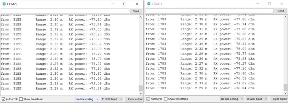
According to our setup, we have placed the anchor and tag at a distance of 1 meter from each other but the Serial Monitor shows a distance above 2 meters.
From here we can say, the measured distance is incorrect. This is because of the Antenna Delay problem. The DW1000 Antenna delay is internal to the chip and not included in the Time of Flight (TOF) calculation. Thus we need to calibrate this Antenna Delay issue.
What is Antenna Delay of DW1000?
DecaWave’s DW1000, a multi-channel transceiver based on Ultra Wideband (UWB) radio communications, allows very accurate time-stamping of messages as they leave from and arrive at the transceiver.
The delays which are measured in these timestamps include the propagation delay through the DW1000 devices from the points at which the transmitter timestamps are applied to the points at which the receiver timestamps are captured. These delays are referred to as the
transmit/receive antenna delays.
These antenna delays are internal to the chip and not included in the Time of Flight (ToF) but are included in the propagation delay from transmission timestamp to receive message timestamp.
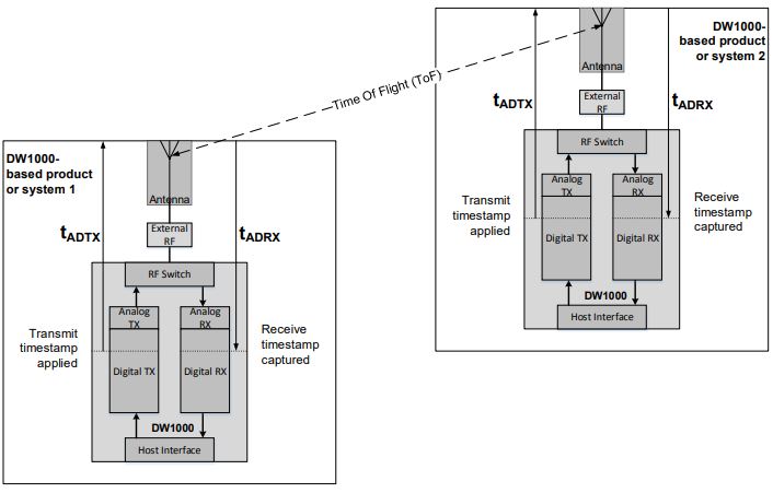
𝑡𝑀𝑒𝑎𝑠𝑢𝑟𝑒𝑑 = 𝑡𝐴𝐷𝑇𝑋 + 𝑇𝑜𝐹 + 𝑡𝐴𝐷𝑅𝑋
where:
ToF = Time of Flight
tMeasured = The measured time from the transmit timestamp to the receive timestamp
tADTX = Transmit antenna delay
tADRX = Receive antenna delay
The internal propagation delays in DW1000 devices vary slightly from chip to chip. There can also be variations due to components between DW1000 and the antenna. Since we are measuring RF signals moving at the speed of light these variations can make differences to ranging measurements in the tens of centimeters. Antenna delay calibration is used to remove these variations.
Antenna Delay Calibration of DW1000
To fix the Antenna Delay issue the above Thomas Trojer’s DW1000 library is modified by Jim Remington.
The updated DW1000 library from Jim can be downloaded from jremington Github repository. With the antenna calibration, the distance measuring seems more accurate.
Delete the old DW1000 library from the Arduino Library folder and add the latest downloaded jremington DW1000 library file to the Arduino library folder.
ESP32 Anchor Autocalibrate Code
Copy the following code and upload it to the first ESP32 UWB Board.
In the following code, make changes to the following line:
|
1 |
float this_anchor_target_distance = 1; //measured distance to anchor in m |
Replace the distance at which you are calibrating.
|
1 2 3 4 5 6 7 8 9 10 11 12 13 14 15 16 17 18 19 20 21 22 23 24 25 26 27 28 29 30 31 32 33 34 35 36 37 38 39 40 41 42 43 44 45 46 47 48 49 50 51 52 53 54 55 56 57 58 59 60 61 62 63 64 65 66 67 68 69 70 71 72 73 74 75 76 77 78 79 80 81 82 83 84 85 86 87 88 89 90 91 92 93 94 95 96 97 98 99 100 |
#include <SPI.h> #include "DW1000Ranging.h" #include "DW1000.h" // ESP32_UWB pin definitions #define SPI_SCK 18 #define SPI_MISO 19 #define SPI_MOSI 23 #define DW_CS 4 // connection pins const uint8_t PIN_RST = 27; // reset pin const uint8_t PIN_IRQ = 34; // irq pin const uint8_t PIN_SS = 4; // spi select pin char this_anchor_addr[] = "84:00:22:EA:82:60:3B:9C"; float this_anchor_target_distance = 1; //measured distance to anchor in m uint16_t this_anchor_Adelay = 16600; //starting value uint16_t Adelay_delta = 100; //initial binary search step size void setup() { Serial.begin(115200); while (!Serial); //init the configuration SPI.begin(SPI_SCK, SPI_MISO, SPI_MOSI); DW1000Ranging.initCommunication(PIN_RST, PIN_SS, PIN_IRQ); //Reset, CS, IRQ pin Serial.print("Starting Adelay "); Serial.println(this_anchor_Adelay); Serial.print("Measured distance "); Serial.println(this_anchor_target_distance); DW1000.setAntennaDelay(this_anchor_Adelay); DW1000Ranging.attachNewRange(newRange); DW1000Ranging.attachNewDevice(newDevice); DW1000Ranging.attachInactiveDevice(inactiveDevice); //Enable the filter to smooth the distance //DW1000Ranging.useRangeFilter(true); //start the module as anchor, don't assign random short address DW1000Ranging.startAsAnchor(this_anchor_addr, DW1000.MODE_LONGDATA_RANGE_LOWPOWER, false); } void loop() { DW1000Ranging.loop(); } void newRange() { static float last_delta = 0.0; Serial.print(DW1000Ranging.getDistantDevice()->getShortAddress(), DEC); float dist = 0; for (int i = 0; i < 100; i++) { // get and average 100 measurements dist += DW1000Ranging.getDistantDevice()->getRange(); } dist /= 100.0; Serial.print(","); Serial.print(dist); if (Adelay_delta < 3) { Serial.print(", final Adelay "); Serial.println(this_anchor_Adelay); // Serial.print("Check: stored Adelay = "); // Serial.println(DW1000.getAntennaDelay()); while(1); //done calibrating } float this_delta = dist - this_anchor_target_distance; //error in measured distance if ( this_delta * last_delta < 0.0) Adelay_delta = Adelay_delta / 2; //sign changed, reduce step size last_delta = this_delta; if (this_delta > 0.0 ) this_anchor_Adelay += Adelay_delta; //new trial Adelay else this_anchor_Adelay -= Adelay_delta; Serial.print(", Adelay = "); Serial.println (this_anchor_Adelay); // DW1000Ranging.initCommunication(PIN_RST, PIN_SS, PIN_IRQ); //Reset, CS, IRQ pin DW1000.setAntennaDelay(this_anchor_Adelay); } void newDevice(DW1000Device *device) { Serial.print("Device added: "); Serial.println(device->getShortAddress(), HEX); } void inactiveDevice(DW1000Device *device) { Serial.print("delete inactive device: "); Serial.println(device->getShortAddress(), HEX); } |
ESP32 UWB Setup Tag Code
Copy the following code and upload it to the second ESP32 UWB Board.
|
1 2 3 4 5 6 7 8 9 10 11 12 13 14 15 16 17 18 19 20 21 22 23 24 25 26 27 28 29 30 31 32 33 34 35 36 37 38 39 40 41 42 43 44 45 46 47 48 49 50 51 52 53 54 55 56 57 58 59 |
#include <SPI.h> #include "DW1000Ranging.h" #include "DW1000.h" #define SPI_SCK 18 #define SPI_MISO 19 #define SPI_MOSI 23 #define DW_CS 4 // connection pins const uint8_t PIN_RST = 27; // reset pin const uint8_t PIN_IRQ = 34; // irq pin const uint8_t PIN_SS = 4; // spi select pin // TAG antenna delay defaults to 16384 // leftmost two bytes below will become the "short address" char tag_addr[] = "7D:00:22:EA:82:60:3B:9C"; void setup() { Serial.begin(115200); delay(1000); //init the configuration SPI.begin(SPI_SCK, SPI_MISO, SPI_MOSI); DW1000Ranging.initCommunication(PIN_RST, PIN_SS, PIN_IRQ); //Reset, CS, IRQ pin DW1000Ranging.attachNewRange(newRange); DW1000Ranging.attachNewDevice(newDevice); DW1000Ranging.attachInactiveDevice(inactiveDevice); // start as tag, do not assign random short address DW1000Ranging.startAsTag(tag_addr, DW1000.MODE_LONGDATA_RANGE_LOWPOWER, false); } void loop() { DW1000Ranging.loop(); } void newRange() { Serial.print(DW1000Ranging.getDistantDevice()->getShortAddress(), HEX); Serial.print(","); Serial.println(DW1000Ranging.getDistantDevice()->getRange()); } void newDevice(DW1000Device *device) { Serial.print("Device added: "); Serial.println(device->getShortAddress(), HEX); } void inactiveDevice(DW1000Device *device) { Serial.print("delete inactive device: "); Serial.println(device->getShortAddress(), HEX); } |
Calculating the Adelay Parameter
After uploading the code, open the both Serial Monitor. Place the module at a fix distance of 1 meter. Then press the reset button.
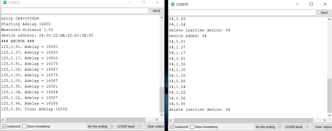
The DW1000 Antenna Delay Calibration factor called Adelay can be determined from the code. In the Serial Monitor, the Adelay factor is something like 16586. Copy this number as it is required in the final Code.
Measuring the distance Accurately with Adelay inclusion
Now the DW1000 Antenna Delay Calibration factor called Adelay is determined. Therefore, we need to upload the final code to the Anchor board. The code for tag remains the same.
ESP32 UWB Setup Anchor Code
The code needs modification in these two lines.
|
1 2 |
uint16_t Adelay = 16611; float dist_m = 1; //meters |
Replace the Adelay factor in the code and also mention the distance at which you found the factor.
|
1 2 3 4 5 6 7 8 9 10 11 12 13 14 15 16 17 18 19 20 21 22 23 24 25 26 27 28 29 30 31 32 33 34 35 36 37 38 39 40 41 42 43 44 45 46 47 48 49 50 51 52 53 54 55 56 57 58 59 60 61 62 63 64 65 66 67 68 69 70 71 72 73 74 75 76 77 78 79 80 81 82 83 84 85 86 87 88 89 90 |
#include <SPI.h> #include "DW1000Ranging.h" #include "DW1000.h" // leftmost two bytes below will become the "short address" char anchor_addr[] = "84:00:5B:D5:A9:9A:E2:9C"; //#4 //calibrated Antenna Delay setting for this anchor uint16_t Adelay = 16611; // previously determined calibration results for antenna delay // #1 16630 // #2 16610 // #3 16607 // #4 16580 // calibration distance float dist_m = 1; //meters #define SPI_SCK 18 #define SPI_MISO 19 #define SPI_MOSI 23 #define DW_CS 4 // connection pins const uint8_t PIN_RST = 27; // reset pin const uint8_t PIN_IRQ = 34; // irq pin const uint8_t PIN_SS = 4; // spi select pin void setup() { Serial.begin(115200); delay(1000); //wait for serial monitor to connect Serial.println("Anchor config and start"); Serial.print("Antenna delay "); Serial.println(Adelay); Serial.print("Calibration distance "); Serial.println(dist_m); //init the configuration SPI.begin(SPI_SCK, SPI_MISO, SPI_MOSI); DW1000Ranging.initCommunication(PIN_RST, PIN_SS, PIN_IRQ); //Reset, CS, IRQ pin // set antenna delay for anchors only. Tag is default (16384) DW1000.setAntennaDelay(Adelay); DW1000Ranging.attachNewRange(newRange); DW1000Ranging.attachNewDevice(newDevice); DW1000Ranging.attachInactiveDevice(inactiveDevice); //start the module as an anchor, do not assign random short address DW1000Ranging.startAsAnchor(anchor_addr, DW1000.MODE_LONGDATA_RANGE_LOWPOWER, false); // DW1000Ranging.startAsAnchor(ANCHOR_ADD, DW1000.MODE_SHORTDATA_FAST_LOWPOWER); // DW1000Ranging.startAsAnchor(ANCHOR_ADD, DW1000.MODE_LONGDATA_FAST_LOWPOWER); // DW1000Ranging.startAsAnchor(ANCHOR_ADD, DW1000.MODE_SHORTDATA_FAST_ACCURACY); // DW1000Ranging.startAsAnchor(ANCHOR_ADD, DW1000.MODE_LONGDATA_FAST_ACCURACY); // DW1000Ranging.startAsAnchor(ANCHOR_ADD, DW1000.MODE_LONGDATA_RANGE_ACCURACY); } void loop() { DW1000Ranging.loop(); } void newRange() { // Serial.print("from: "); Serial.print(DW1000Ranging.getDistantDevice()->getShortAddress(), HEX); Serial.print(", "); #define NUMBER_OF_DISTANCES 1 float dist = 0.0; for (int i = 0; i < NUMBER_OF_DISTANCES; i++) { dist += DW1000Ranging.getDistantDevice()->getRange(); } dist = dist/NUMBER_OF_DISTANCES; Serial.println(dist); } void newDevice(DW1000Device *device) { Serial.print("Device added: "); Serial.println(device->getShortAddress(), HEX); } void inactiveDevice(DW1000Device *device) { Serial.print("Delete inactive device: "); Serial.println(device->getShortAddress(), HEX); } |
Testing the Final Code
After uploading the new code in the Anchor part, open the Serial Monitor. As the anchor and tag both are placed at a distance of 1 meters from each other, the Serial Monitor should show 1 meter distance.
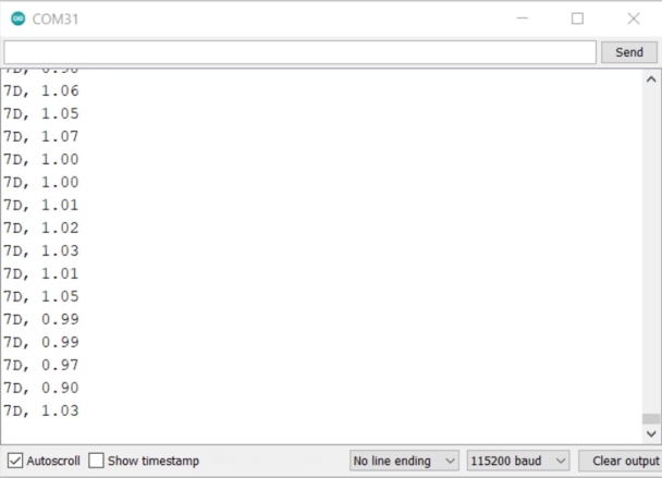
Now let us do some other testing by moving the tag to half a meter distance from the anchor.
At this instance the Serial Monitor will show a distance of around 0.5 meters which seems nearly accurate.
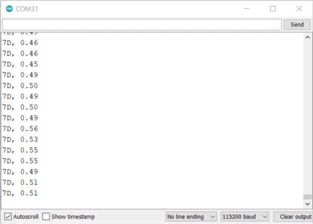
With a proper Adelay set, the measurement accuracy could be improved greatly. So, this is how you can Get Started with ESP32 UWB (Ultra Wideband) Board and measure the distance.
Video Tutorial & Guide

You may also refer to some of our articles related to UWB Technology using DW1000/300 Chip to have a more clear understanding:
- ESP32 DW1000 UWB Indoor Location Positioning System
- Ranging & Localization with ESP32 UWB DW3000 Module
- ESP32 UWB Pro – Ultra Wideband Module with Amplifier
- ESP32 DW3000 UWB Module Achieving 500m Range


7 Comments
Really thank you for your tutorial.
I have just a question.
In my scenario, I have a generic group of people, each of them, with a ESP32-UWB device.
I don’t know anything on the devices (their address, tag, Ancor or not) and I would only to know if and when some of them are really close (less than 1m) .
Can I use these devices?
I tried using the DWM1001C but they mast be in a network but this is not my scenario.
Thank you for any help
Yes you can use it similar to apple air tags to a distance lesser than 1 meter.
uploading the anchor and tag sketch my boards run in Guru Meditation on Core1
any suggestion?
What GPIO pins cannot be used on this board when the UWB feature is enabled? For example, some pins on the ESP-Wroom-32 cannot be used when WiFi is enabled, so are there any such pins on this board? Are they the same as ESP-Wroom-32? Thanks.
The board uses the same ESP32-WROOM chips, so the pins are same.
I followed the instructions in your tutorial, but unfortunately I am getting this as an output on the serial monitor-” device address: 83:17:5B:D5:A9:9A:E2:9C
ANCHOR ###”. And for the code for the tag, a similar output which is – “device address: 7D:00:22:EA:82:60:3B:9C
TAG ###”. The only difference in our codes is that I had to take out the arguments passed in the “SPI.begin()” function call. It states that this function call must come with empty arguments. So which particular SPI library should I download to make the initialization of the MOSI, MISO and SCK possible? The one I am currently using is the Adafruit BusIO by Adafruit Version 1.14.0
Hello. How can i TDoA implementation for this module(4 anchors or more and 1 tag or more)? Do you have any code for TDoA?