

Overview
In this advanced tutorial, we will learn how to Send/Receive Data to nRF Connect Mobile App with the Seeed XIAO BLE nRF52840 Sense. This tutorial covers the details about the Mobile App called nRF Connect. The nRF Connect App for Mobile is a powerful generic tool that aids the development of Bluetooth Low Energy devices. The app allows users to scan and explore their devices and communicate with them.
Using the nRF Connect App, we will send one or zero commands to control the onboard LED of Seeed XIAO BLE nRF52840 Sense. The Seeed XIAO BLE Board also has a port for battery connection. This measures the battery voltage and sends it to the nRF Connect app. In the final part, we will be sending the DHT11 Humidity and temperature data to the nRF Connect app and monitor the data wirelessly.
This tutorial is very interesting as you will learn how to send any sensor data to any mobile app wirelessly over BLE Connection. But before this, you can check the earlier two tutorials related to Seeed XIAO nRF52840 Boards:
1. Getting Started with Seeed XIAO BLE nRF52840 Sense
2. Using IMU & Microphone on XIAO BLE nRF52840 Sense
Seeed XIAO BLE nRF52840 Sense
First, let’s have a short overview of these boards. These boards are based on Nordic nRF52840 BLE 5.0 Chip from Nordic Semiconductor. One of the boards is called Seeed XIAO BLE nRF52840 and the other is Seeed XIAO BLE nRF52840 Sense.

p>These boards are small-sized, ultra-low-power Bluetooth development boards. One of the boards features an onboard Bluetooth antenna, and onboard battery charging chip which makes it ideal for IoT projects. The other board called the XIAO Sense board has additional features like 6 DOF IMU and a PDM microphone which make it an ideal board to run AI using TinyML and TensorFlow Lite.

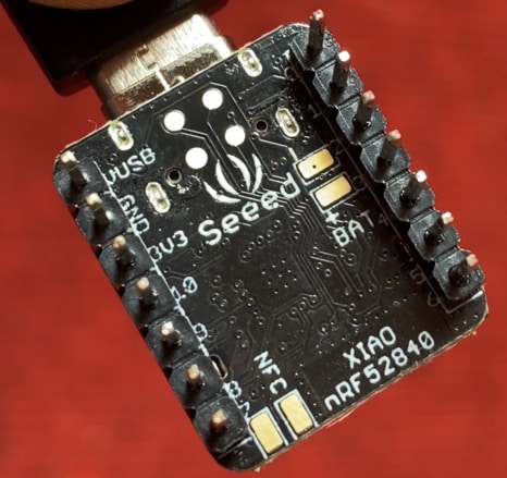
The topside of the board has a reset button, 6 DOF IMU LSM6DS3TR-C, Bluetooth Antenna, PDM Microphone, RGB LED & power LED. On the backside of the board, there are SWD Pins for Debugging and Reflashing Bootloader using JLink. There are pair of pins to connect the NFC Antenna & also a 3.7V Lithium-Ion Battery.
There are 11 digital I/O that can be used as PWM pins and 6 analog I/O that can be used as ADC pins. It supports UART, IIC, and SPI all three common serial ports.
BLE States
Before moving to the practical part, you need to have proper knowledge of BLE states. The BLE states include Standby state, Advertising state, Scanning state, Initiating state, Connection State and Synchronization state.

• Standby state: There is no transmission or reception of packets in this state. This state can be entered from any other BLE state.
• Advertising state: A BLE device in this state is called “Advertiser”. This state can be reached from the “standby state”. The link-layer will transmit advertising packets and listens to and responds to responses triggered due to advertising packets.
• Scanning state: In this state, the link-layer listens for advertising packets from other advertising devices. The BLE device in this state is known as a “scanner”. This state can be reached from the “standby state”.
• Initiating state: The BLE device in this state is known as the initiator. This BLE state can be reached from the “standby state”. Link-layer listens for advertising physical packets from specific BLE devices. It also responds to these packets to initiate a connection from another device.
• Connection State: This state can be reached either from the “initiating state” or “advertising state”. In this connection state, there are two roles of the BLE device either master or slave. When it has entered from “initiating state” it will be in the master role. When it has entered from “advertising state” it will be in a slave role. In the master role, the link-layer will communicate with the device in the slave role and defines the timings of transmissions.
• Synchronization state: This state can be entered from the “standby state”. The link layer in this state listens for periodic channel packets from a specified device transmitting periodic advertising.
What is nRF Connect App

nRF Connect for Mobile is a powerful generic tool that allows you to scan and explore your Bluetooth Low Energy devices and communicate with them. nRF Connect for Mobile supports a number of Bluetooth SIG adopted profiles, as well as the Device Firmware Update profile (DFU) from Nordic Semiconductor or Eddystone from Google.
- Scans for Bluetooth Low Energy devices
- Parses advertisement data
- Shows RSSI graph
- Connects to any connectable Bluetooth Low Energy device
- Discovers and parses services and characteristics
- Allows read/write of characteristics
- Allows enable/disable of notifications and indications
- Logs events and method calls
- Supports Device Firmware Update profile which allows users to upload a new application over-the-air (DFU OTA) from a HEX or Zip file
- Parses values of most of the known characteristics
- GATT server configuration
- Listing paired devices
- Bluetooth Low Energy Advertising (peripheral role)
- Simultaneous scanning, advertising, and maintaining multiple connections
- Full support for Eddystone beacons and iBeacons
- Supports Device Firmware Update (DFU) profile
Controlling XIAO BLE nRF52840 onboard LED with Mobile App
In the first example, we will control the onboard LED of XIAO BLE nRF52840 Sense using the Mobile App called nRF Connect.
For that go to your phone play store and search for nRF Connect App. Then install the app.

In order to use BLE functionalities, you need to download a library called Arduino BLE. From this GitHub repository download this library and add it to the Arduino Library folder using add zip option.
Now copy the following code and upload it to the Seeed XIAO BLE nRF52840 Sense Board.
|
1 2 3 4 5 6 7 8 9 10 11 12 13 14 15 16 17 18 19 20 21 22 23 24 25 26 27 28 29 30 31 32 33 34 35 36 37 38 39 40 41 42 43 44 45 46 47 48 49 50 51 52 53 54 55 56 57 58 59 60 61 62 63 64 65 66 67 68 69 70 |
#include <ArduinoBLE.h> BLEService ledService("19B10000-E8F2-537E-4F6C-D104768A1214"); // Bluetooth® Low Energy LED Service // Bluetooth® Low Energy LED Switch Characteristic - custom 128-bit UUID, read and writable by central BLEByteCharacteristic switchCharacteristic("19B10001-E8F2-537E-4F6C-D104768A1214", BLERead | BLEWrite); const int ledPin = LED_BUILTIN; // pin to use for the LED void setup() { Serial.begin(9600); while (!Serial); // set LED pin to output mode pinMode(ledPin, OUTPUT); // begin initialization if (!BLE.begin()) { Serial.println("starting Bluetooth® Low Energy module failed!"); while (1); } // set advertised local name and service UUID: BLE.setLocalName("LED"); BLE.setAdvertisedService(ledService); // add the characteristic to the service ledService.addCharacteristic(switchCharacteristic); // add service BLE.addService(ledService); // set the initial value for the characeristic: switchCharacteristic.writeValue(0); // start advertising BLE.advertise(); Serial.println("BLE LED Peripheral"); } void loop() { // listen for Bluetooth® Low Energy peripherals to connect: BLEDevice central = BLE.central(); // if a central is connected to peripheral: if (central) { Serial.print("Connected to central: "); // print the central's MAC address: Serial.println(central.address()); // while the central is still connected to peripheral: while (central.connected()) { if (switchCharacteristic.written()) { if (switchCharacteristic.value()) { Serial.println("LED on"); digitalWrite(ledPin, LOW); // changed from HIGH to LOW } else { Serial.println(F("LED off")); digitalWrite(ledPin, HIGH); // changed from LOW to HIGH } } } // when the central disconnects, print it out: Serial.print(F("Disconnected from central: ")); Serial.println(central.address()); } } |
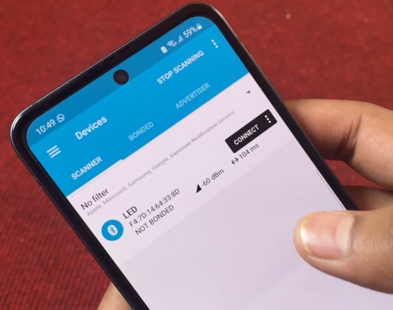
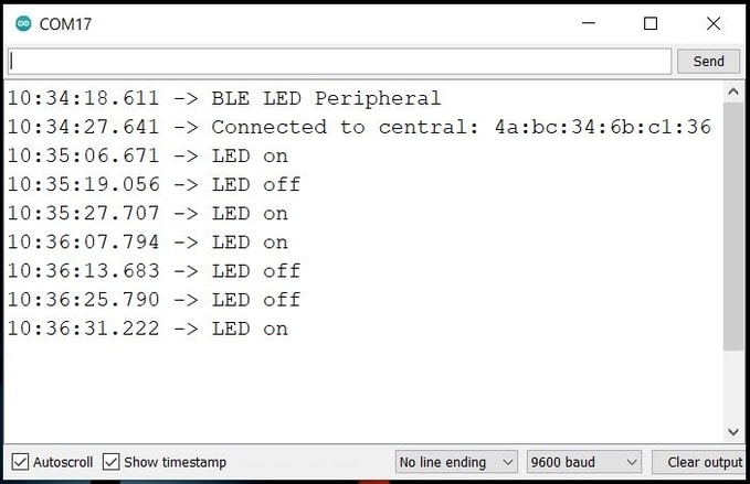
Once the code is uploaded, open the Serial Monitor. Then on your mobile phone open the nRF Connect App.
In the app part, when scanning is done the LED will appear on the app. Click on connect so that a connection between nRF52840 BLE Module and Mobile App will establish.
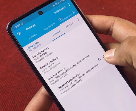
In the client part, three services will appear. Click on the 3rd one as Unknown service.
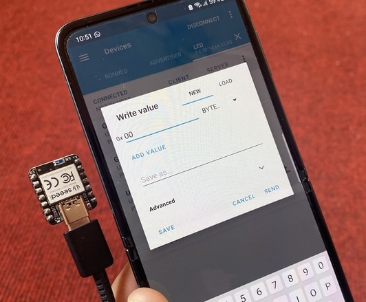
Click on the download sign again. A hex value will appear as 0x00. If you click on the upload sign, a pop-up will appear where you need to send either zero or one value.
If you send 0x01 the onboard LED will turn on. And then when you send 0x00 the onboard LED will turn off.
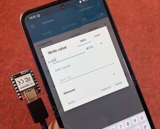
So this is how you can send commands from a mobile app to control an LED. You can also check the Serial Monitor part, it will show you the on-off status as per every command.
Reading XIAO BLE nRF52840 Battery Level on nRF Connect Mobile App
In this 2nd example, we will use an analog pin to read the battery level. In the XIAO BLE Module, if you look at the back you will see there are 2 gold-plated pins where you can connect a single cell Lithium-Ion Battery.
The module also has a battery charging chip BQ25101 which is internally connected to Analog pin A0. You can measure the battery voltage or you can convert the voltage into a percentage.
Here is the code for monitoring Battery voltage/ percentage of the nRF52840 Chip on the nRF Connect Mobile App.
|
1 2 3 4 5 6 7 8 9 10 11 12 13 14 15 16 17 18 19 20 21 22 23 24 25 26 27 28 29 30 31 32 33 34 35 36 37 38 39 40 41 42 43 44 45 46 47 48 49 50 51 52 53 54 55 56 57 58 59 60 61 62 63 64 65 66 67 68 69 70 71 72 73 74 75 76 77 78 79 80 81 82 83 84 85 86 87 88 89 90 |
#include <ArduinoBLE.h> // Bluetooth® Low Energy Battery Service BLEService batteryService("180F"); // Bluetooth® Low Energy Battery Level Characteristic BLEUnsignedCharCharacteristic batteryLevelChar("2A19", BLERead | BLENotify); // standard 16-bit characteristic UUID // remote clients will be able to get notifications if this characteristic changes int oldBatteryLevel = 0; // last battery level reading from analog input long previousMillis = 0; // last time the battery level was checked, in ms void setup() { Serial.begin(9600); // initialize serial communication while (!Serial); pinMode(LED_BUILTIN, OUTPUT); // initialize the built-in LED pin to indicate when a central is connected // begin initialization if (!BLE.begin()) { Serial.println("starting BLE failed!"); while (1); } BLE.setLocalName("BatteryMonitor"); BLE.setAdvertisedService(batteryService); // add the service UUID batteryService.addCharacteristic(batteryLevelChar); // add the battery level characteristic BLE.addService(batteryService); // Add the battery service batteryLevelChar.writeValue(oldBatteryLevel); // set initial value for this characteristic // start advertising BLE.advertise(); Serial.println("Bluetooth® device active, waiting for connections..."); } void loop() { // wait for a Bluetooth® Low Energy central BLEDevice central = BLE.central(); // if a central is connected to the peripheral: if (central) { Serial.print("Connected to central: "); // print the central's BT address: Serial.println(central.address()); // turn on the LED to indicate the connection: digitalWrite(LED_BUILTIN, HIGH); // check the battery level every 200ms // while the central is connected: while (central.connected()) { long currentMillis = millis(); // if 200ms have passed, check the battery level: if (currentMillis - previousMillis >= 200) { previousMillis = currentMillis; updateBatteryLevel(); } } // when the central disconnects, turn off the LED: digitalWrite(LED_BUILTIN, LOW); Serial.print("Disconnected from central: "); Serial.println(central.address()); } } void updateBatteryLevel() { /* Read the current voltage level on the A0 analog input pin. This is used here to simulate the charge level of a battery. */ int battery = analogRead(A0); int batteryLevel = map(battery, 0, 1023, 0, 100); if (batteryLevel != oldBatteryLevel) // if the battery level has changed { Serial.print("Battery Level % is now: "); // print it Serial.println(batteryLevel); batteryLevelChar.writeValue(batteryLevel); // and update the battery level characteristic oldBatteryLevel = batteryLevel; // save the level for next comparison } } |
In this code, we assign BLE Service and also the 16 Bit UUID number.
Using the analog read function, we determine the battery voltage, and using the map function we convert the battery voltage into a percentage. Finally, with the help of Arduino BLE Library, we send the battery level to nRF Connect Mobile App.
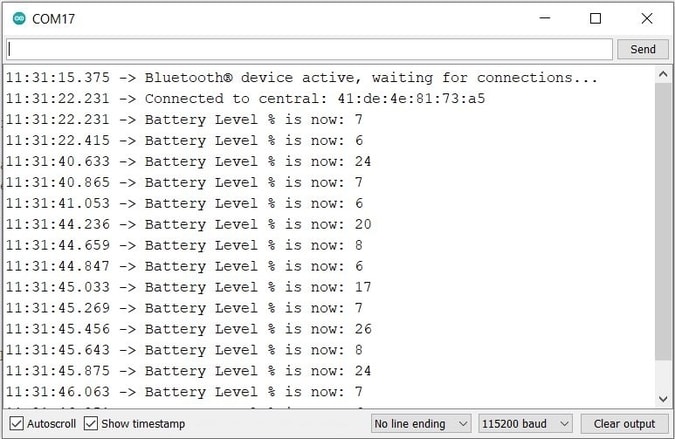
Now upload this code to the XIAO BLE Board and then open the Serial Monitor. The BLE will get activated and will show waiting for a connection.
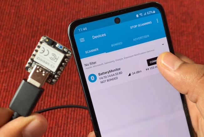
Open the nRF Connect app on your phone and connect to the Battery Level device. On the Client, part click on Battery Service. So Battery level UUID will be shown. Click on the download logo. Here the battery percentage will appear.
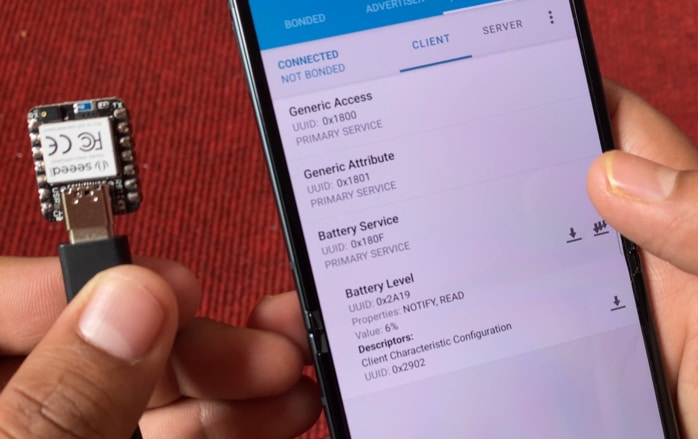
This is the battery percentage when nothing is connected to the analog pin. If you connect 3.3V to the A0 pin and then observe the battery percentage, it will appear as 100%. Similarly, if you connect the A0 pin to GND, the battery percentage will appear as 0%.
You can also check the battery percentage on Serial Monitor.
Sending DHT11 Sensor Data to nRF Connect App
Now let us interface DHT11 Humidity Temperature Sensor with Seeed XIAO BLE nRF52840 Sense Board & send the data to nRF Connect Mobile App.
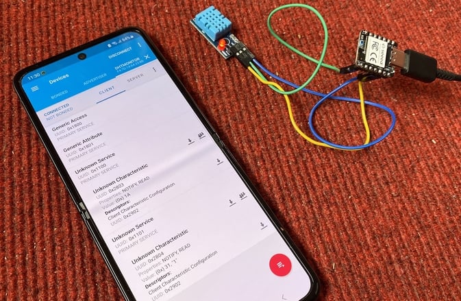
For this connect the VCC, GND & Output pin of the DHT111 Sensor to Seeed XIAO BLE Board 3.3V, GND & D7 pin respectively. You can use jumper wires to connect it.
Now copy the following code and upload it to the BLE XIAO Board.
|
1 2 3 4 5 6 7 8 9 10 11 12 13 14 15 16 17 18 19 20 21 22 23 24 25 26 27 28 29 30 31 32 33 34 35 36 37 38 39 40 41 42 43 44 45 46 47 48 49 50 51 52 53 54 55 56 57 58 59 60 61 62 63 64 65 66 67 68 69 70 71 72 73 74 75 76 77 78 79 80 81 82 83 84 85 86 87 88 89 90 91 92 93 94 95 96 97 98 99 100 101 102 103 104 105 106 107 108 109 |
#include <ArduinoBLE.h> #include <dht.h> #define dht_pin 7 // Analog Pin sensor is connected to dht DHT; int temperature;; int humidity; int oldtemperature = 0; int oldhumidity = 0; // Bluetooth® Low Energy Service BLEService tempService("1100"); BLEService humService("1101"); // Bluetooth® Low Energy Battery Level Characteristic BLEUnsignedCharCharacteristic temperatureChar("2803", BLERead | BLENotify); // standard 16-bit characteristic UUID BLEUnsignedCharCharacteristic humidityChar("2804", BLERead | BLENotify); // standard 16-bit characteristic UUID // remote clients will be able to get notifications if this characteristic changes long previousMillis = 0; // last time the dht value was checked, in ms void setup() { Serial.begin(9600); // initialize serial communication while (!Serial); pinMode(LED_BUILTIN, OUTPUT); // initialize the built-in LED pin to indicate when a central is connected // begin initialization if (!BLE.begin()) { Serial.println("starting BLE failed!"); while (1); } BLE.setLocalName("DhtMonitor"); BLE.setAdvertisedService(tempService); // add the service UUID tempService.addCharacteristic(temperatureChar); // add the temperature characteristic BLE.addService(tempService); // Add the temperature service temperatureChar.writeValue(oldtemperature); // set initial value for this characteristic BLE.setAdvertisedService(humService); // add the service UUID humService.addCharacteristic(humidityChar); // add the humidity characteristic BLE.addService(humService); // Add the humidity service humidityChar.writeValue(oldhumidity); // set initial value for this characteristic // start advertising BLE.advertise(); Serial.println("Bluetooth® device active, waiting for connections..."); } void loop() { // wait for a Bluetooth® Low Energy central BLEDevice central = BLE.central(); // if a central is connected to the peripheral: if (central) { Serial.print("Connected to central: "); // print the central's BT address: Serial.println(central.address()); // turn on the LED to indicate the connection: digitalWrite(LED_BUILTIN, HIGH); while (central.connected()) { long currentMillis = millis(); if (currentMillis - previousMillis >= 200) { previousMillis = currentMillis; updatedht(); } } // when the central disconnects, turn off the LED: digitalWrite(LED_BUILTIN, LOW); Serial.print("Disconnected from central: "); Serial.println(central.address()); } } void updatedht() { DHT.read11(dht_pin); temperature = DHT.temperature; humidity = DHT.humidity; if ((temperature != oldtemperature) || (humidity != oldhumidity)) // if the dht value has changed { Serial.print("Temperature: "); // print it Serial.print(temperature); Serial.println("*C"); Serial.print("Humidity: "); // print it Serial.print(humidity); Serial.println("%"); temperatureChar.writeValue(temperature); // and update the temperature oldtemperature = temperature; // save the level for next comparison humidityChar.writeValue(humidity); // and update the humidity oldhumidity = humidity; // save the level for next comparison } } |
In BLE Service we assigned two services 1100 and 1101. Similarly, we assigned 2803 and 2804 as UUID numbers for temperature and humidity values.
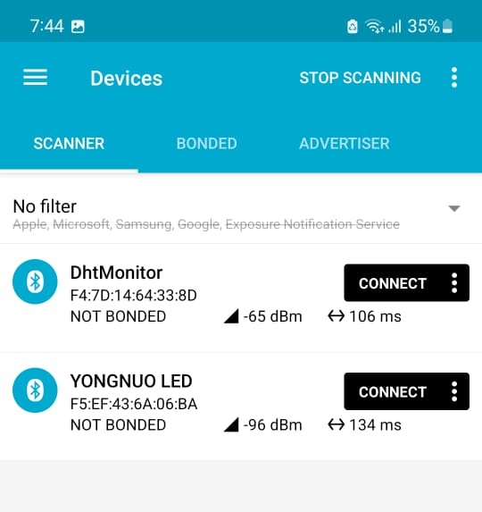
Now upload this code. Then open the Serial Monitor. The BLE will be active again and Serial Monitor will show waiting for connections. Now go to nRF Connect App and scan it. The DHT Monitor will appear. So click on connect.
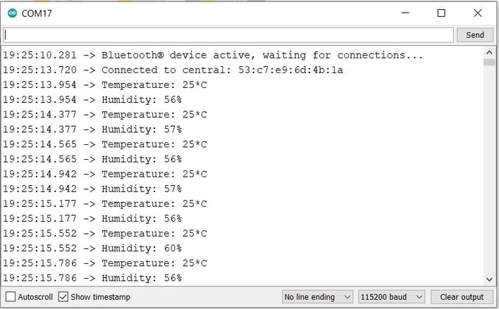
Once the phone establishes a connection, the temperature-humidity value is shown on the serial monitor.
After connection click on unknown service. One of the unknown services with UUID 2803 is for temperature and another unknown service with UUID 2804 is for humidity.

Click on the download logo. So it’s showing value as 1A. Now the 1A is a hex value which in decimal means 26. So the temperature is 26 degrees.

Similarly in the other unknown service, the hex value appears as 31. The 31 in hexadecimal is equivalent to 49. So the humidity is 49%.
So this is how you can Send/Receive Sensor Data to Mobile App with Seeed XIAO BLE nRF52840 Sense & on nRF Connect Application.
Video Tutorial & Guide


11 Comments
I have been able to create and implement an Arduino sketch on the SEEED nrf52840, based on your DHT example. Mine uses the Bosch BMP180 Pressure/Temperature sensor which is read over I2C. When the 52840 is connected to the Arduino IDE, the sketch is compiled and uploaded, the nRF Connect app on my android phone is able to detect and connect as well as read the data from the BMP180.
However, if I instead connect the nRF52840 a battery pack(5V) or a USB hub, the nRF Connect can not connect. In fact, scanning does not detect the 52840. It’s as if it is not advertising unless it’s connected to the Arduino IDE.
I have tried multiple times, as well as reconnected to the Arduino IDE.
Is there assume sort of reset or boot process that is needed to get the 52840 to run independently?
yes I too facing the same issues have you find any solution for this problem???
In your setup() code block do you have the following statement?
while (!Serial);
If so, when the XAIO is connected to a USB power brick it will wiat the XAIO will wait for a serial respnse – which will never come. Try commenting out this line e.g.
//while (!Serial);
In your setup() block do you have this code which waits for the serial line to respond?
while (!Serial);
If so, try commenting it out and reloading your sketch.
//while (!Serial);
The other problem you may have is the ISB power bank turning off. Most power banks are designed to charge mobile phones, and when the current they deliver drops below 50-100 mA the switch off. A basic XIAO only draws about 4 mA so a power bank is likely to switch off after, typically, 30 seconds.
ArduinoBLE is not compatible with the XIAO NRF52840 Board. I have no idea how this was ever working.
Your battery code is the only thing I’ve found that works – thanks!!!
I agree with Banana. I am unable to compile ArduinoBLE library without getting “not compatible with this board”, and posts show it is compatible with only a few boards. Is there a trick to get this compiling? Otherwise, I also have no idea how this would ever work (yes, I even went back a few versions and they don’t compile either).
It is only compatible selecting as MBED in Arduino IDE
https://forum.seeedstudio.com/t/xiao-ble-wont-compile-arduinoble-arduino-ide/264917/8
Do you know how to get OTA updates working using NRF connect?
are you sure that the a0 delivery the charge state? iam found no information about this