

Overview
In this getting started tutorial, we will learn about the latest Seeed XIAO BLE nRF52840 Sense Board from Seeedstudio. Recently they launched 2 boards based on Nordic nRF52840 BLE 5.2 Chip from Nordic Semiconductor. One of the board is called as Seeed XIAO BLE nRF52840 and other as Seeed XIAO BLE nRF52840 Sense.
The Seeed XIAO BLE is an ultra-small size, ultra-low power Bluetooth development board based on the Nordic nRF52840. It features an onboard Bluetooth antenna, and onboard battery charging chip which makes it ideal for IoT projects. Similarly, Seeed XIAO BLE nRF52840 Sense is a tiny Bluetooth BLE development board designed for IoT and AI applications. It features an onboard antenna, 6 Dof IMU, and microphone, all of which make it an ideal board to run AI using TinyML and TensorFlow Lite.
Earlier, we learned about Makerfabs nRF52840 Board which is little large board. But Seeed XIAO BLE nRF52840 is a simplified board.
This tutorial covers following parts:
- Learn about the differences between XIAO BLE nRF52840 and XIAO BLE nRF52840 Sense
- Go through the Board design, Pins Description & Functions
- Setup Arduino IDE to use nRF52840 Board
- Writing an Arduino Code to Blink an LED
- Learning how to use ADC Pin to control Light Intensity
- Reading Temperature & Humidity Value from DHT11 Sensor
- Displaying text on 0.96″ I2C OLED Display
Seeed XIAO BLE nRF52840 (Sense)
The Seeed XIAO BLE is developed from a powerful Nordic nRF52840 microcontroller which is designed in a Bluetooth 5.2 chipset. The chip is built around a 32-bit ARM® Cortex™-M4 CPU with a Floating-Point Unit(FPU) operating at 64Mhz. The best part about this module is it only consumes 5 μA in the deep sleep model. The board has a BQ25101 chip that supports battery charge management. To better support IoT and TinyML AI projects, there is an advanced version “Seeed XIAO BLE Sense” that carries both 6-axis IMU and PDM microphones.

The board has a tiny and elegant reset button on one side of the Type-C interface. On the other side, it is designed in a three-in-one LED along with power LED. There are 11 digital i/o that can be used as PWM pins and 6 analog i/o that can be used as ADC pins. It supports UART, IIC, and SPI all three common serial ports. The board has onboard 2 MB flash which means it can also be programmed by Arduino, MicroPython, and CircuitPython. The board supports Near Field Communication(NFC).
Specifications
- Powerful CPU: Nordic nRF52840, ARM® Cortex™-M4 32-bit processor with FPU operating at 64 MHz
- Wireless capabilities: Bluetooth 5.0, NFC, and ZigBee module with onboard antenna
- Ultra-small size: 21 x 17.5mm, Seeed Xiao series classic form-factor for wearable devices
- Ultra-low sleep power: 5 μA, deep sleep model
- Battery charging chip: BQ25101 chip supported lithium battery charge management
- Rich interface: 1x Reset button, Ix UART, 1x IIC, 1x SPI, 1x NFC, 1x SWD, 11x GPIO, 6x ADC, 1x Three-in-one LED,1x User LED
- Onboard 2 MB flash
- Onboard PDM microphone and 6-axis IMU (only for XIAO BLE nRF52840 Sense)
- Single-sided components, surface mounting design
Seeed XIAO BLE nRF52840 VS Seeed XIAO BLE nRF52840 Sense
| Item | Seeed XIAO BLE – nRF52840 | Seeed XIAO BLE Sense – nRF52840 |
| Processor | Nordic nRF52840 | The same as XIAO BLE |
| ARM® Cortex®-M4 with FPU run up to 64 MHz | ||
| Wireless | Bluetooth 5.0/NFC/Zigbee | The same as XIAO BLE |
| On-chip Memory | 1 MB flash and 256 kB RAM | The same as XIAO BLE |
| Onboard Memory | 2 MB QSPI flash | The same as XIAO BLE |
| Interface | 1xUART, 1xIIC, 1xSPI, 1xNFC, 1xSWD, | The same as XIAO BLE |
| 11xGPIO(PWM), 6xADC | ||
| Sensors | Onboard PDM digital microphone | |
| Onboard 6-axis IMU | ||
| Dimensions | 21 x 17.5mm | The same as XIAO BLE |
| Power | Circuit operating voltage: 3.3V@200mA | The same as XIAO BLE |
| Charging current: 50mA/100mA | ||
| Input voltage (VIN): 5V | ||
| Standby power consumption: <5μA |
Hardware Pinout
There are 11 digital i/o that can be used as PWM pins and 6 analog i/o that can be used as ADC pins. It supports UART, IIC, and SPI all three common serial ports.

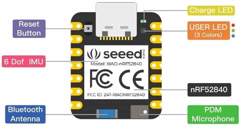
The topside of the board has reset button, 6 DOF IMU LSM6DS3TR-C, Bluetooth Antenna, PDM Microphone, RGB LED & power LED.
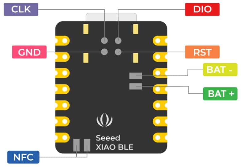
On the backside of the board there are SWD Pins for Debugging and Reflashing Bootloader using JLink. There are pair of pins to connect the NFC Antenna & also a 3.7V Lithium-Ion Battery.
Setting Up Arduino IDE
Now let us learn how we can use Seeed XIAO BLE nRF52840 (Sense) with Arduino IDE. First we need to setup the Arduino IDE for programming.

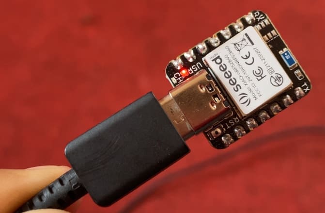
Connect the XIAO BLE (Sense) to your computer via a USB Type-C cable.
Software Setup
Download and Install the latest version of Arduino IDE according to your operating system. Then launch the Arduino application.
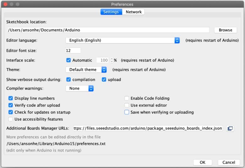
There is no pre-installed package for NRF52840 Board. So we need to first install the board on Arduino IDE. To do that Navigate to File > Preferences, and fill “Additional Boards Manager URLs” with the URL below:
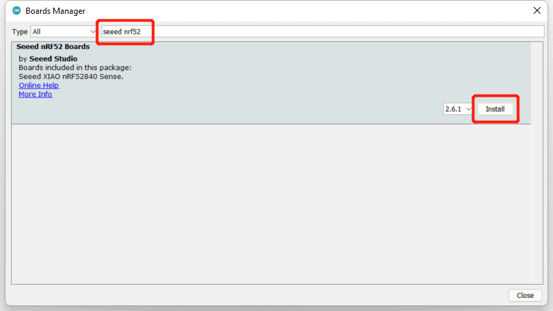
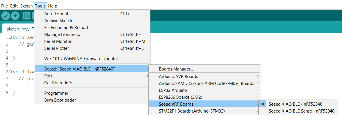
Navigate to Tools > Board > Boards Manager, type the keyword “seeed nrf52” in the search box, select the latest version of Seeed nRF52 Boards, and install it.
After installing the board package, navigate to Tools > Board > Seeed nRF Boards and select “Seeed XIAO BLE – nRF52840“. Now we have finished setting up the XIAO BLE (Sense) for Arduino IDE.
Navigate to Tools > Port and select the serial port. You can get the port number from the Device Manager.
Writing an Arduino Code to Blink an LED
Navigate to File > Examples > Basics > Blink to open Blink example. Then upload the code.
|
1 2 3 4 5 6 7 8 9 10 11 12 13 |
// the setup function runs once when you press reset or power the board void setup() { // initialize digital pin LED_BUILTIN as an output. pinMode(LED_BUILTIN, OUTPUT); } // the loop function runs over and over again forever void loop() { digitalWrite(LED_BUILTIN, HIGH); // turn the LED on (HIGH is the voltage level) delay(1000); // wait for a second digitalWrite(LED_BUILTIN, LOW); // turn the LED off by making the voltage LOW delay(1000); // wait for a second } |
After uploading the code, the on-board will turn-ON and OFF for 1 second.
Using ADC Pin to control the LED Brightness
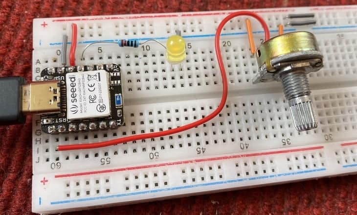
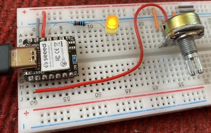
Now lets use a Potentiometer to control the LED brightness. The potentiometer will act as an input and LED will act as output. Here is a simple connection diagram.

Connect the pin1, pin2 & pin3 of potentiometer to 3.3V, analog pin A0 & GND of XIAO BLE nRF52840 respectively. Connect the positive pin of LED to digital pin 10 via 220-ohm resistor. Connect the LED GND to GND.
Copy the following code and upload it to the Seeed XIAO BLE nRF52840 (Sense) Board.
|
1 2 3 4 5 6 7 8 9 10 11 12 13 14 15 16 17 18 19 20 21 |
const int LED = 10; const int analog_ip = A0; int inputVal = 0; float mv_per_lsb = 3300.0F / 1024.0F; // 10-bit ADC with 3.3V input range void setup() { Serial.begin(115200); while ( !Serial ) delay(10); // for nrf52840 with native usb pinMode (LED, OUTPUT); } void loop() { inputVal = analogRead(analog_ip); Serial.println(inputVal); Serial.print((float)inputVal * mv_per_lsb); Serial.println(" mV"); analogWrite (LED, inputVal); delay(100); } |
After the code gets uploaded, you can open Serial Monitor and start rotating the potentiometer knob. The Serial Monitor will display some analog values with the ADC voltage ranging from 0-3.3V.
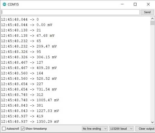
Similarly the LED brightness increases or decreases on the basis of potentiometer rotation.
<
Reading Temperature & Humidity Value from DHT11 Sensor
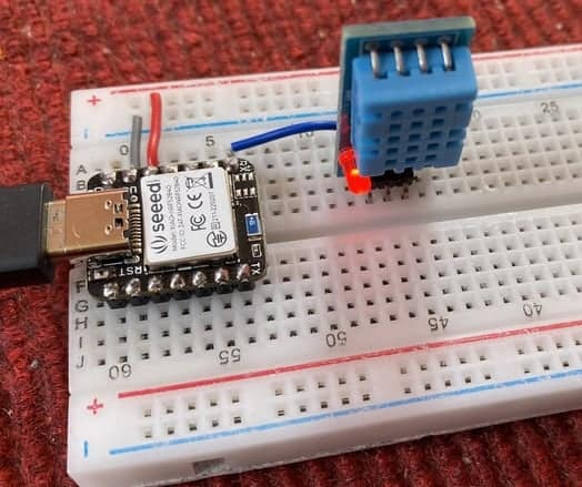
Now let us interface DHT11 Humidity sensor with Seeed XIAO BLE nRF52840 Sense. The DHT11 is a basic, ultra low-cost digital temperature and humidity sensor. It uses a capacitive humidity sensor and a thermistor to measure the surrounding air, and spits out a digital signal on the data pin.

Connect the VCC & GND Pin of DHT11 Sensor to nRF52840 3.3V & GND Pin respectively. Connect the digital output pin of DHT11 Sensor to digital pin 7 of XIAO BLE nRF52840.
To use this code with Arduino IDE, you need to install DHT11 Library.
Now copy the following code and upload it to the Seeed XIAO nRF52840 board.
|
1 2 3 4 5 6 7 8 9 10 11 12 13 14 15 16 17 18 19 20 21 22 23 24 25 26 |
#include <dht.h> #define dht_pin 7 // Analog Pin sensor is connected to dht DHT; void setup() { Serial.begin(9600); delay(500); } void loop() { DHT.read11(dht_pin); Serial.print("Humidity: "); Serial.print(DHT.humidity); Serial.println("% "); Serial.print("Temperature: "); Serial.print(DHT.temperature); Serial.println("°C "); Serial.println(); delay(2000); } |
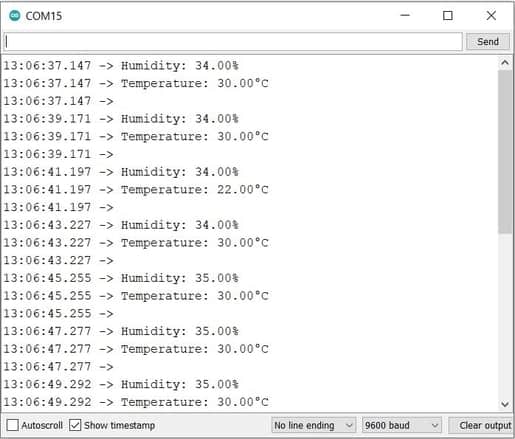
After uploading the code, open Serial Monitor and you can see the temperature and Humidity data displayed on Serial Monitor.
Displaying text on 0.96″ I2C OLED Display
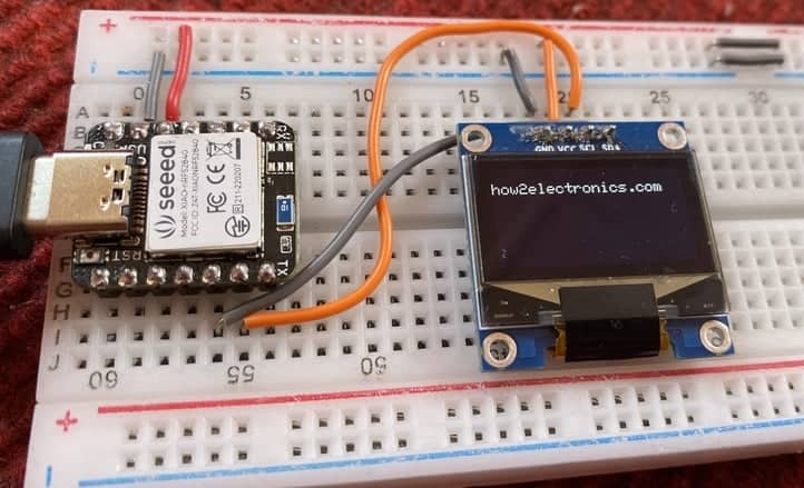
Now let us interface SSD1306 0.96″ I2C OLED Display with Seeed XIAO nRF52840 Sense. The connection is fairly simple as shown in image below.
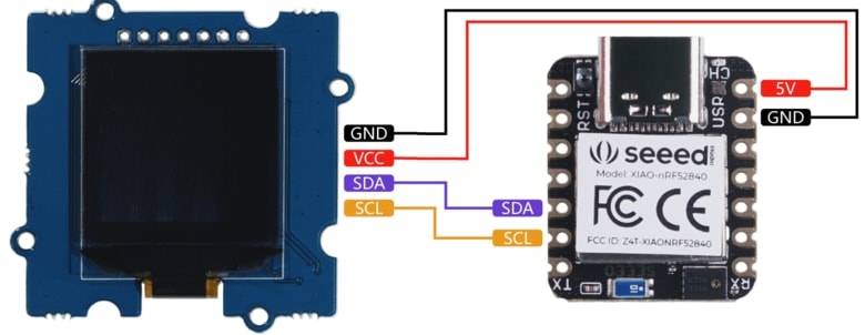
Connect the VCC & GND pin of OLED Display to nRF5840 3.3V & GND Pin. Also, connect the SDA & SCL Pin of OLED to nRF5840 SDA & SCL Pin.
To use this code with Arduino IDE, you need to install Adafruit GFX Library and also Adafruit SSD1306 Library.
Now copy the following code and upload it to the Seeed XIAO nRF52840 board.
|
1 2 3 4 5 6 7 8 9 10 11 12 13 14 15 16 17 18 19 20 21 22 23 24 25 26 27 28 29 30 31 32 33 |
#include <Wire.h> #include <Adafruit_GFX.h> #include <Adafruit_SSD1306.h> #define SCREEN_WIDTH 128 // OLED display width, in pixels #define SCREEN_HEIGHT 64 // OLED display height, in pixels // Declaration for an SSD1306 display connected to I2C (SDA, SCL pins) Adafruit_SSD1306 display(SCREEN_WIDTH, SCREEN_HEIGHT, &Wire, -1); void setup() { Serial.begin(115200); if(!display.begin(SSD1306_SWITCHCAPVCC, 0x3C)) // Address 0x3D for 128x64 { Serial.println(F("SSD1306 allocation failed")); for(;;); } delay(2000); display.clearDisplay(); display.setTextSize(1); display.setTextColor(WHITE); display.setCursor(0, 10); // Display static text display.println("how2electronics.com"); display.display(); } void loop() { } |
As soon as the code gets uploaded the OLED Display will start displaying the text assigned in the code part.
Video Tutorial & Guide

The advanced version or the next part of this tutorial can be followed via the following links:
- Using IMU & Microphone on XIAO BLE nRF52840 Sense
- Send/Receive Data to Mobile App with XIAO BLE nRF52840 Sense


