

Overview
In this guide, we will learn how to use DWIN HMI LCD Display with ESP32 WiFi Module. Currently, DWIN HMI Displays are very popular in the Maker’s market. Using the DGUS Software we can design any UI and control the UI Content with a microcontroller. The 7-inch DMG80480C070 Display has a resolution of 800X480 pixels. We can interface the display with any with 5V compatible microcontroller board like Arduino, ESP8266, ESP32, PIC, 8051, STM32, etc.
For this demo, we will make a Smart Home Controller using DWIN HMI Display & ESP32 Module. The BME280 will read the temperature, humidity, pressure, and dew point and display the data on DWIN Screen. Similarly, we will also control a 4-channel Relay Module using the UI/widgets on DWIN Screen.
Before moving ahead, you can refer to our previous guide on these displays:
- Getting started with DWIN HMI TFT LCD Display
- Interfacing DWIN HMI TFT LCD Display with Arduino
- IoT AC Energy Meter with ESP32 & HMI Display
The Smart Home Controller Project using DWIN HMI Display & ESP32 uses a 7-inch DWIN LCD Display DMG80480C070 and other components. The project comprises the following steps:
- Installing required Software & Tools
- Designing the GUI of Display
- Upload project files to the Display
- Interface sensor and relays to the ESP32
- Make a UART communication between ESP32 & DWIN HMI Display
- Monitor sensor data & Control AC Home appliances from this touch display
Bill of Materials
| S.N. | Components | Quantity | Purchase Links |
|---|---|---|---|
| 1 | ESP32 WiFi Module | 1 | Amazon | AliExpress |
| 2 | DWIN LCD Display Kit | 1 | dwin-global.com |
| 3 | BME280 Sensor | 1 | Amazon | AliExpress |
| 4 | 4 Channel Relay Module | 1 | Amazon | AliExpress |
| 6 | Breadboard | 1 | Amazon | AliExpress |
| 7 | Jumper Wires | 4 | Amazon | AliExpress |
| 8 | Micro-USB Cable | 1 | Amazon | AliExpress |
Installing Required Software & Tools
DGUS(DWIN Graphic Utilized Software) is a cost-effective GUI software platform developed by DWIN Technology. Based on the K600+ Kernel hardware platform, GUI design, combined with a simple command interface, can be achieved quickly, eliminating the need for complicated programming and expensive development environments.
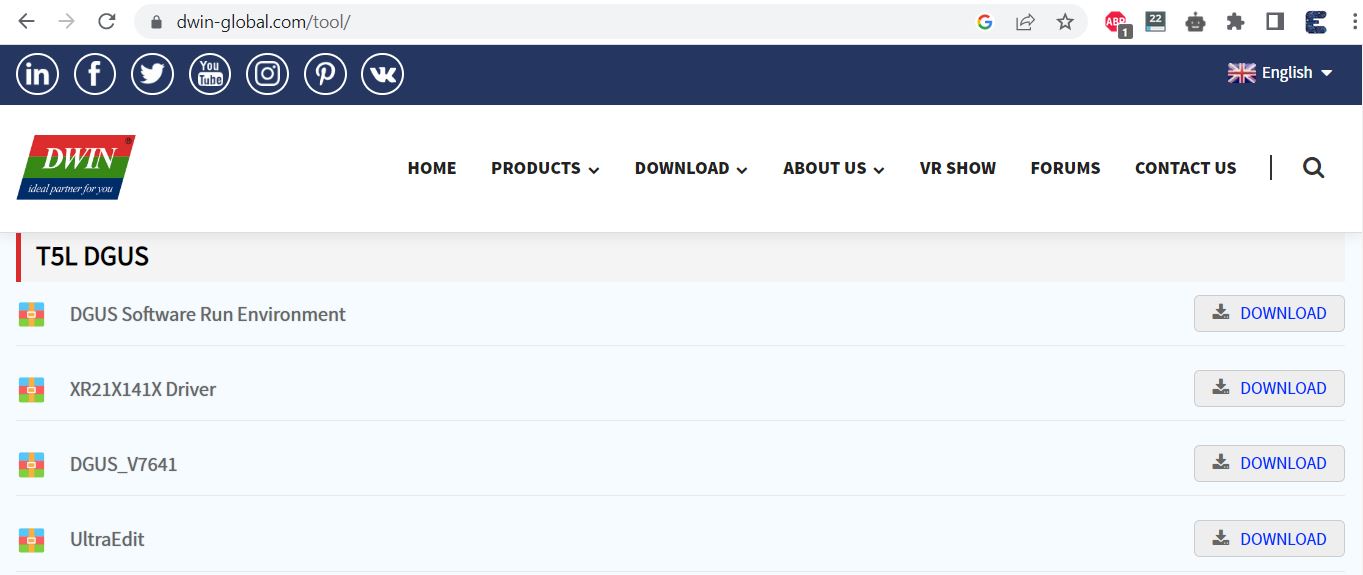
Download the DGUS Software from the above link and then extract the folder. Open the extracted folder and run the executable file called ‘DGUS_V7.642.exe‘. A DGUS Window will open. Initially, you need to change to the English language as the Chinese language is set by default.
You need to download the XR21X141X Driver software for establishing communication with your computer and DGUS Software.
After downloading install the software into your computer system.
Creating Images & Icons for GUI on DGUS Software
The DMG80480C070 screen resolution is 800×480. So we need to create images and icons under the same resolution. For the Smart Home project part, the 3 images that I created are:

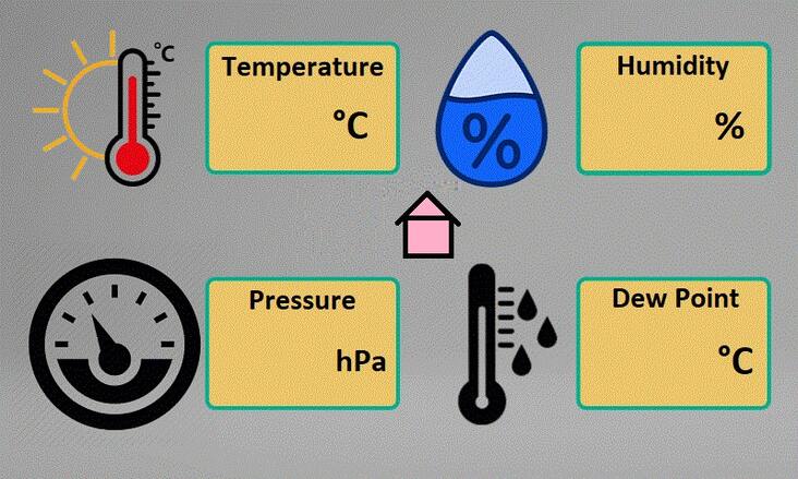

All the images should be in .bmp format. The images should be named 00.bmp, 01.bmp, and 02.bmp as the naming is important. You can use Photoshop to create images and save the file in .bmp format.
Similarly I have created two icons for this project. The icons are used as ON/OFF buttons. As per the UI requirements, the icon size is 160×80. The icon can be in jpg or png format and should be named as 01, 02 and so on.
![]()
Creating UI using DGUS Software
Create a Folder on the Desktop and give it any name like “DWIN Smart Home”. This folder will have all the files required and created while designing the UI.
Open the DGUS Software and Create a New Project. Select the resolution of 800×480 and the location of the project under the folder you created on your Desktop. Then hit ok

The project window will appear now. On the left side, click on the ‘+’ sign and import all the 3 images for UI that are in .bmp format.

All the images are imported now. Now we need to create UI using the particular area on this screen.
Before that we need to generate .icl files for images and icons. To do that go to Settings and Click on DGUS. A window will pop up. On this window click on ICL Tool.
From this window click on Select Pictures. Then select all the 3 images.
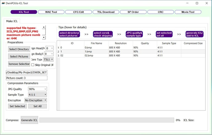
Click on Generate ICL option. You will be asked to save the file. Save the file with the name 32.icl. Hence the ICL file for UI is successfully created.
Similarly we need to generate the ICL files for icons. Import 2 icon files the same way you did above and click on Generate ICL. Save the file with the name 42.icl. Hence ICL files for Icons is also created now.
Designing Home Page UI
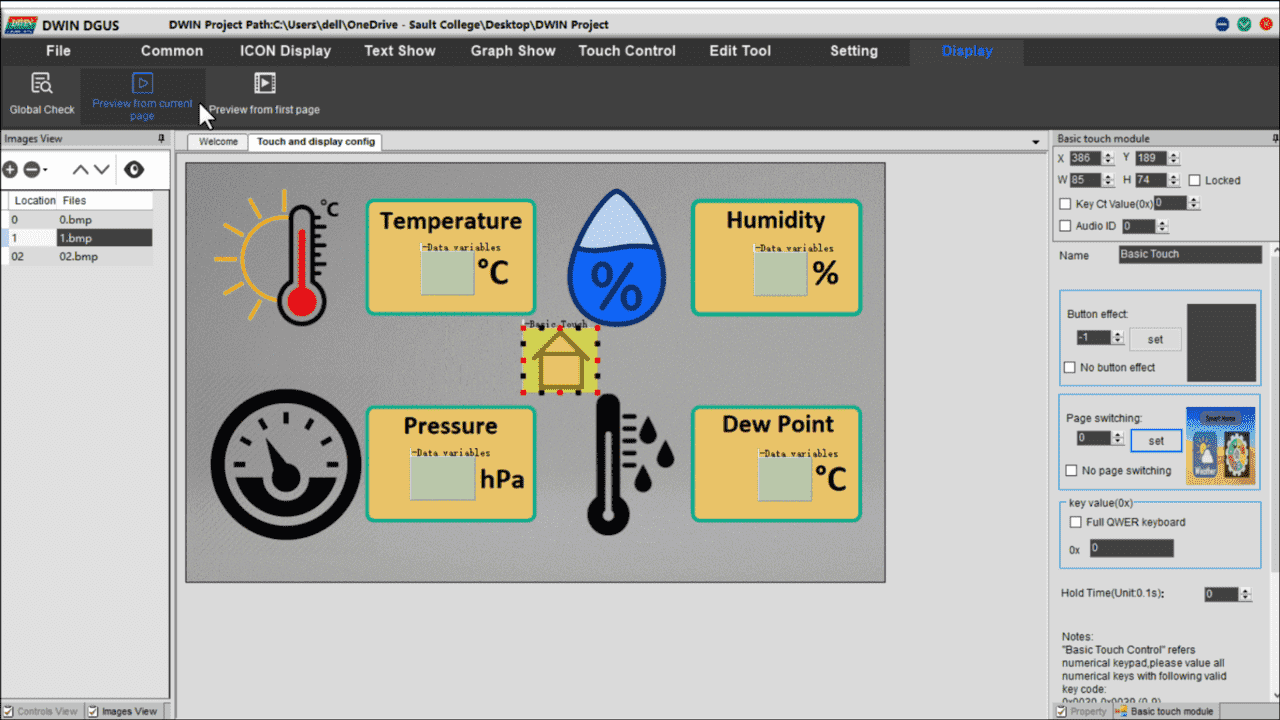
We need to create a Touch button for the Display now. For that select, the “00.bmp” image then click on the “Touch Control” Menu. Click on the basic touch module then select the widget area where you want to apply this module. You can drag, drop and resize the module as your requirement.

Now on the left side select the images for page switching. For the first touch select “0.01.bmp” and for 2nd touch select “0.01.bmp”. So the first-page setup is done.
Designing 1st Page UI
Now Switch to the “01.bmp” image and from the ‘Text Show’ option, select ‘Data Variable Display’.

Place the box in front of the unit for all 4 parameters (temperature, humidity, pressure, dew point). The box will show the numeric value from the Sensor.
On the right side, there are options and boxes that should be filled with the following options.
- VP(0x): 6100 for Temperature, 6200 for Humidity, 6300 for Pressure, and 6400 for Dew Point.
- Font Size: 24
- Alignment: Left
- Automatic Character Spacing Adjustment (Ticked)
- Display Invalid Zero (Ticked)
- Variable Type: int(2 bytes)
- Integer Digits: 2
- Decimal Digit: 0
- Variable Unit Length: 0
- Show Unit: Blank
- Initial Value: 0
Make sure you are making changes to all 4 parameters. Every setting remains the same except the VP Address.
Go to Basic Touch Module and assign a Page switch option, so that you can go back to the home page. For that drag and adjust the basic touch module on the home symbol as shown in the above image and select the page switching option to the home page.
Designing 2nd Page UI
Now let’s design our toggle switch buttons for controlling Appliances like lights, AC, Fan, TV, etc. Switch to the “02.bmp” image and from the ‘ICON Display’ option, select ‘Variable Icon Display’.
![]()
Go to ICON Display Menu and choose Var ICON Display. Select the area where you want to display your icon. As always resize the module as your needs. Now choose your VP address as 6500.
Choose the icon ICL file as 42.icl. When the Value is Minimum select the OFF icon i.e zero icon. Similarly, set the maximum value as 1 and select the ON icon i.e one icon. Keep the display mode as transparency.
Now from the touch control menu select the increment adjustment module. You can resize the module. Then select data auto uploading. Click on the no-button effect. Give the same VP address as 6500. Click on Low Byte. Select the Adjust method as ++ and over limit operation as a cycle. Similarly, adjust step length to 1 and upper limit to 1. Finally, set the touch effect as a disposable setting.

Now, copy the Var Icon module and paste them onto the Fan, AC, and TV controller buttons. But, change the VP address as; 6600 for Light, 6700 for Fan, 6800 for TV respectively. Also, copy and paste the incremental adjustment module and set their VP address accordingly.
Finally, we have completed adding modules to our UI. Now Click on Save and Generate, to generate 13 touch file, 14 show file, and 22 config bin files.
Generating Font File
Go to the welcome page and click on word bank generating. Here choose your font and adjust your settings with font size as 24 and select any font you want to display. Then click on create to create your font file.

The font file will be created on the DGUS software folder by the name “0_DWIN_ASC.HZK” copy it and paste it into the DWIN_SET folder.
Uploading TFT Files to DWIN HMI LCD Display
Once the UI is created and saved, you can upload the firmware to the LCD Display memory. In case you need a ready-made file like mine, you can download the project files from the link below.
If you don’t know how to upload the project to this touch display then follow my previous Getting Started Tutorial. In I have explained two processes to upload the project to your display using an SD card and the T5L Download tool.
This is the result of our newly created UI After uploading the project file to the display.


ESP32 & DWIN Display Hardware Setup
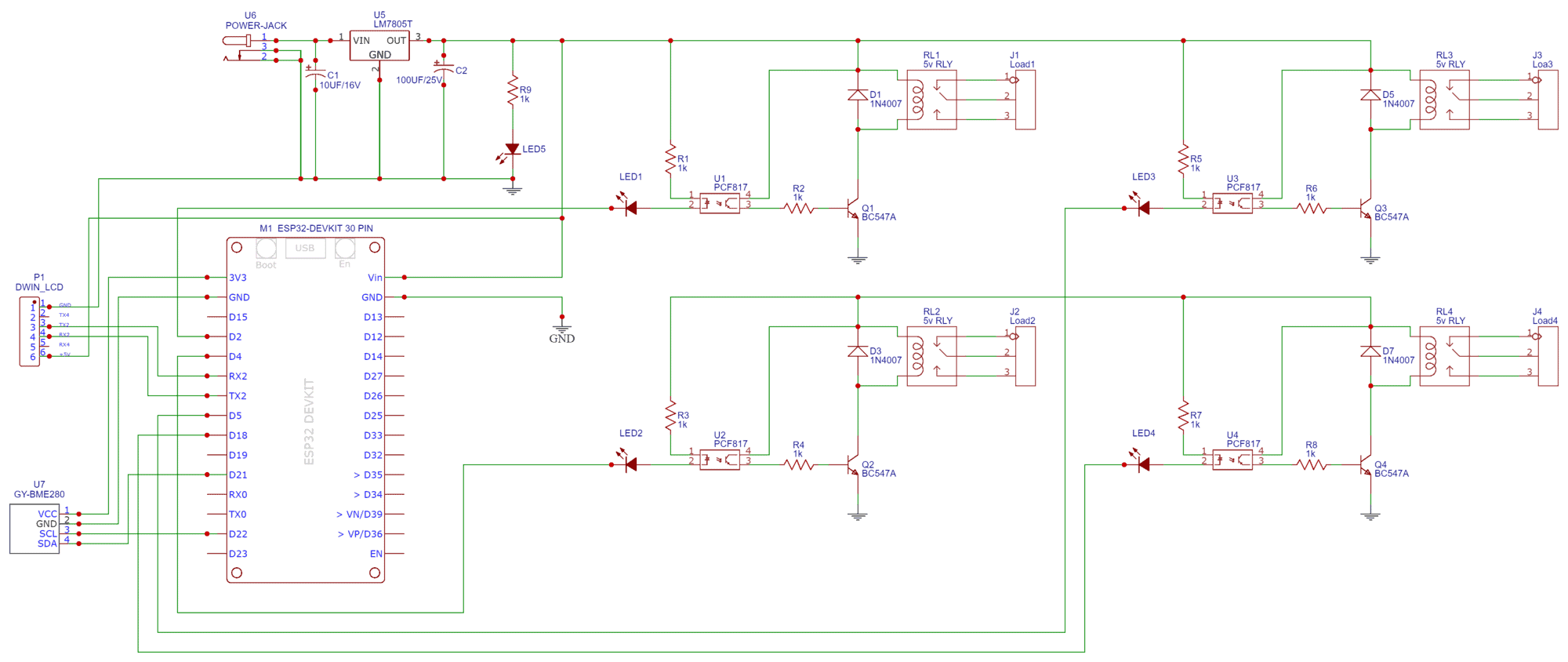
After being done with the GUI design you have to connect the BME280 sensor and Relay module to the ESP32 board. Here is the connection diagram for the project.

For the demo, I am using 4 different colors of LED instead of the Relay Module.

For Serial Communication between DWIN LCD Display and ESP32 Board, I am using UART2 pins of ESP32. Therefore connect the TX2 & RX2 Pin of ESP32 to DWIN Display RX2 & TX2 Pin respectively.

If you are providing power from two different power sources to ESP32 and LCD separately then you need to connect the GND of Display to the GND Pin of ESP32.
Project PCB Gerber File & Ordering PCB Online
If you don’t want to assemble the circuit on a breadboard and you want PCB for the project, then here is the PCB for you. I used EasyEDA to draw the schematic first.
Then I converted the schematic to PCB. The PCB Board for this project looks something like below.
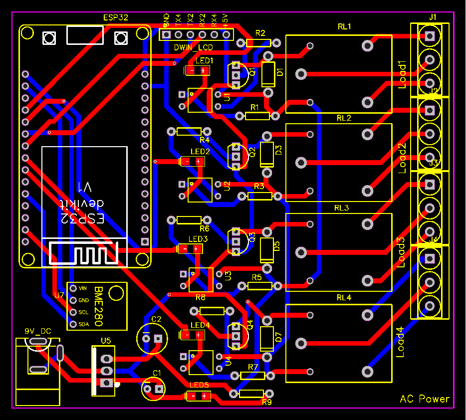
The Gerber File for the PCB is given below. You can simply download the Gerber File and order the PCB from ALLPCB at 1$ only.
You can use this Gerber file to order high quality PCB for this project. To do that visit the ALLPCB official website by clicking here: https://www.allpcb.com/.

You can now upload the Gerber File by choosing the Quote Now option. From these options, you can choose the Material Type, Dimensions, Quantity, Thickness, Solder Mask Color and other required parameters.

After filling all details, select your country and shipping method. Finally you can place the order.
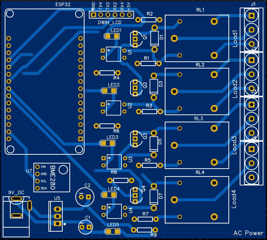
The 2D view of the PCB is simply amazing which should look in real while assembling all the components on a PCB.
Source Code/Program
Now let us see the code part, for receiving sensor data and displaying of LCD Screen along with controlling relays from the screen.
In this project, we need to send and receive data. For sending purposes, I am sending a frame with a VP address of that sensor and value, and that value is updated on Display. Similarly for receiving I am checking the serial receive frame for a particular button with their VP address using a switch case as you can see in the program code.
For code compilation add the BME280 Library to the Library folder using the Library manager.
This is the syntax of the frame which I am sending to the HMI-Display to display the sensor data.
|
1 2 3 4 |
unsigned char Temperature[8] = {0x5a, 0xa5, 0x05, 0x82, temperature_add , 0x00, 0x00, 0x00}; unsigned char Humidity[8] = {0x5a, 0xa5, 0x05, 0x82, humidity_add, 0x00, 0x00, 0x00}; unsigned char Pressure[8] = {0x5a, 0xa5, 0x05, 0x82, pressure_add , 0x00, 0x00, 0x00}; unsigned char DewPoint[8] = {0x5a, 0xa5, 0x05, 0x82, dewpoint_add, 0x00, 0x00, 0x00}; |
In void data display to Arduino, we are receiving data from HMI-Display at the time of pressing any button. We have here four switch cases for Light, Fan, AC, and TV. Every button has a particular VP Address, which sends the signal to ESP32 to activate/deactivate the Relay Module.
|
1 2 3 4 5 6 7 8 9 10 11 12 13 14 15 |
void realy_control() { if (dwin.available()) { for (int i = 0; i <= 8; i++) //this loop will store whole frame in buffer array. { Buffer[i] = dwin.read(); } if (Buffer[0] == 0X5A) { switch (Buffer[4]) .................................. .................................. |
Here is the complete code for this project. Copy the following code and upload it to the ESP32 Board.
|
1 2 3 4 5 6 7 8 9 10 11 12 13 14 15 16 17 18 19 20 21 22 23 24 25 26 27 28 29 30 31 32 33 34 35 36 37 38 39 40 41 42 43 44 45 46 47 48 49 50 51 52 53 54 55 56 57 58 59 60 61 62 63 64 65 66 67 68 69 70 71 72 73 74 75 76 77 78 79 80 81 82 83 84 85 86 87 88 89 90 91 92 93 94 95 96 97 98 99 100 101 102 103 104 105 106 107 108 109 110 111 112 113 114 115 116 117 118 119 120 121 122 123 124 125 126 127 128 129 130 131 132 133 134 135 136 137 138 139 140 141 142 143 144 145 146 147 148 149 150 151 152 153 154 155 156 157 158 159 160 161 162 163 164 165 166 167 168 169 170 171 172 173 174 175 176 177 178 179 180 181 182 183 184 185 186 187 188 |
/* For BME280 sensor */ #include <Wire.h> #include <Adafruit_Sensor.h> #include <Adafruit_BME280.h> const byte rxPin = 16; //rx2 const byte txPin = 17; //tx2 HardwareSerial dwin(1); #define SEALEVELPRESSURE_HPA (1013.25) Adafruit_BME280 bme; // I2C /* appliances pins */ int light = 2; int fan = 4; int ac = 5; int tv = 18; /* Adresses of all sensors */ unsigned char Buffer[9]; #define temperature_add 0x61 #define humidity_add 0x62 #define pressure_add 0x63 #define dewpoint_add 0x64 unsigned char Temperature[8] = {0x5a, 0xa5, 0x05, 0x82, temperature_add , 0x00, 0x00, 0x00}; unsigned char Humidity[8] = {0x5a, 0xa5, 0x05, 0x82, humidity_add, 0x00, 0x00, 0x00}; unsigned char Pressure[8] = {0x5a, 0xa5, 0x05, 0x82, pressure_add , 0x00, 0x00, 0x00}; unsigned char DewPoint[8] = {0x5a, 0xa5, 0x05, 0x82, dewpoint_add, 0x00, 0x00, 0x00}; void setup() { Serial.begin(115200); //Begin serial communication DWIN dwin.begin(115200, SERIAL_8N1, rxPin, txPin); unsigned status; status = bme.begin(0x76); if (!status) { Serial.println("Could not find a valid BME280 sensor, check wiring, address, sensor ID!"); while (1) delay(10); } pinMode(light, OUTPUT); pinMode(fan, OUTPUT); pinMode(ac, OUTPUT); pinMode(tv, OUTPUT); digitalWrite(light, LOW); digitalWrite(fan, LOW); digitalWrite(ac, LOW); digitalWrite(tv, LOW); } void loop() { sensor_data(); delay(10); realy_control(); delay(50); } void sensor_data() { int t = bme.readTemperature(); int h = bme.readHumidity(); int p = bme.readPressure() / 100.0F; int d = dewPointFast(t, h); /*------Print data to Serial Monitor------*/ Serial.print("Temperature = "); Serial.print(t); Serial.println(" °C"); Serial.print("Humidity = "); Serial.print(h); Serial.println(" %"); Serial.print("Pressure = "); Serial.print(p); Serial.println(" hPa"); Serial.print("DewPoint = "); Serial.print(d); Serial.println(" °C"); Serial.println(); Temperature[6] = highByte(t); Temperature[7] = lowByte(t); dwin.write(Temperature, 8); Humidity[6] = highByte(h); Humidity[7] = lowByte(h); dwin.write(Humidity, 8); Pressure[6] = highByte(p); Pressure[7] = lowByte(p); dwin.write(Pressure, 8); DewPoint[6] = highByte(d); DewPoint[7] = lowByte(d); dwin.write(DewPoint, 8); } /*----------DewPoint Calculation--------*/ double dewPointFast(double celsius, double humidity) { double a = 17.271; double b = 237.7; double temp = (a * celsius) / (b + celsius) + log(humidity * 0.01); double Td = (b * temp) / (a - temp); return Td; } void realy_control() { if (dwin.available()) { for (int i = 0; i <= 8; i++) //this loop will store whole frame in buffer array. { Buffer[i] = dwin.read(); } if (Buffer[0] == 0X5A) { switch (Buffer[4]) { case 0x65: //for light if (Buffer[8] == 1) { digitalWrite(light, HIGH); Serial.println("Relay1 ON"); } else { digitalWrite(light, LOW); Serial.println("Relay2 OFF"); } break; case 0x66: //for fan if (Buffer[8] == 1) { Serial.println(Buffer[8]); digitalWrite(fan, HIGH); Serial.println("Relay2 ON"); } else { digitalWrite(fan, LOW); Serial.println("Relay2 OFF"); } break; case 0x67: //for AC if (Buffer[8] == 1) { Serial.println(Buffer[8]); digitalWrite(ac, HIGH); Serial.println("Relay3 ON"); } else { digitalWrite(ac, LOW); Serial.println("Relay3 OFF"); } break; case 0x68: //for TV if (Buffer[8] == 1) { Serial.println(Buffer[8]); digitalWrite(tv, HIGH); Serial.println("Relay4 ON"); } else { digitalWrite(tv, LOW); Serial.println("Relay4 OFF"); } break; default: Serial.println("No data.."); } } } } |
Testing & Demonstration
After successful upload of the program, open the serial monitor at the baud rate of 115200 to see the real-time sensor data.
This DWIN LCD will show the home screen UI.

Go to the 2nd page by touching the UI area. The 2nd page will display the BME280 temperature, humidity, pressure, and dew point.

Now go to the 3rd page of the display. The 3rd page will show the UI and buttons to control different relays.

You can click on individual switch buttons to turn ON/OFF the home appliances.
Video Tutorial & Guide

So, we have successfully made this Smart Home Controller Project with DWIN HMI Display and ESP32. The UI looks pretty good in this display.


2 Comments
Is your display 3.3V or 5V ? If 5V is it safe to operate esp32 with it ?
I follow the steps but the second page doesn’t display the sensor data it only display 00
the 3rd page worked well. may you guide me to find the wrong in it?
I tried this code to display even constant number but it didn’t work too
//DWIN
const byte rxPin = 16; //rx2
const byte txPin = 17; //tx2
HardwareSerial dwin(1);
//Sensors adress
#define temperature_add 0x61
unsigned char Temperature[8] = {0x5a, 0xa5, 0x06, 0x82, temperature_add , 0x00, 0x00, 0x01};
void setup() {
// put your setup code here, to run once:
Serial.begin(115200);
//Begin serial communication DWIN
dwin.begin(115200, SERIAL_8N1, rxPin, txPin);
}
void loop() {
// put your main code here, to run repeatedly:
int t = 25;
/——Print data to Serial Monitor——/
Serial.print(“Temperature = “);
Serial.print(t);
Serial.println(” °C”);
Temperature[6] = highByte(t);
Temperature[7] = lowByte(t);
dwin.write(Temperature, 8);
delay(500);
}
Thank you