

Overview
In this tutorial, we will be Interfacing a 7-inch DWIN HMI TFT LCD Display with Arduino Nano Board. Using this DWIN Display we can control various modules like Relay, Servo Motor, and RGB LED. We will also learn how to create the UI using the DGUS Software.
Before moving ahead, go through the DWIN Getting Started Guide to learn more about the DWIN Display and the method to upload the firmware. Since the DWIN Display has UART Interface, we can communicate with Arduino through Serial Communication. Let’s see how we can build this System.
Bill of Materials
For this project, we need the following components. All these components can be purchased through the given link.

| S.N. | Components | Quantity | Purchase Links |
|---|---|---|---|
| 1 | Arduino Nano Board | 1 | Amazon | AliExpress |
| 2 | DWIN LCD Display Kit | 1 | dwin-global.com |
| 3 | Servo Motor SG90 | 1 | Amazon | AliExpress |
| 4 | RGB LED | 1 | Amazon | AliExpress |
| 5 | Relay 5V Single Channel | 1 | Amazon | AliExpress |
| 6 | Breadboard | 1 | Amazon | AliExpress |
| 7 | Jumper Wires | 1 | Amazon | AliExpress |
| 8 | 5V DC Power Supply | 1 | Amazon | AliExpress |
Creating UI using the DGUS Software
DGUS(DWIN Graphic Utilized Software) is a cost-effective GUI software platform developed by DWIN Technology. Based on the K600+ Kernel hardware platform, GUI design, combined with a simple command interface, can be achieved quickly, eliminating the need for complicated programming and expensive development environments.
Download the DGUS Software from the above link and then extract the folder. Open the extracted folder and run the executable file called ‘DGUS_V7.642.exe‘. A DGUS Window will open. Initially, you need to change to the English language as the Chinese language is set by default.
Now follow the video below to design the UI that we will need in this project.

The link for all the files including the DWIN_Set folder, images, ICL files, etc are inside the folder below. You can extract them and use them in your project.
The Homepage of the final UI looks something like this.

Note:
- All the images should have a dimension the same as Screen Resolution (Example: 800×480).
- The images should be named 00, 01, 02, 03, 04 & so on.
- All the images should be in .bmp format (Use Paint to Convert).
- The converted images in the DGUS Software should be saved as 32.icl
- The converted icons in the DGUS Software should be saved as 42.icl
- Each and every module/units have a different Memory Address (assigned as VP). For example in the above UI, the memory address for Servo=5100, Red LED=5200, Green LED=5300, Blue LED=5400 & Relay=5500.
- All the firmware files that need to be uploaded or copied to SD Card should be inside the DWIN_SET Folder.
Interfacing DWIN HMI TFT LCD Display with Arduino
After creating the UI using the DGUS Software, download the firmware to DWIN LCD Display either using the T5L Download tool or using the SD Card. Follow the previous guide.
Before interfacing please check on the back of the DWIN Module whether the TTL Module is enabled or not. In case its not enabled, solder the terminals to enable the TTL Communication.

Now it’s time to interface the DWIN HMI TFT LCD Display with Arduino Nano Board. Follow the following schematic.

Connect the Servo Motor and Relay VCC & GND Pin to Arduino 5V & GND Pin. Also connect the Servo Motor to D3 of Arduino as Servo requires PWM Signal for operation. Connect the Relay output pin to D2 of Arduino. The RGB LED Module is connected to Pin D4, D5, and D6 of Arduino.
Coming to the DWIN LCD Display and Arduino part, UART Serial Communication is required. Therefore connect the TX2, and RX2 of DWIN Display to Arduino RX & TX Pin respectively. Supply the 5V to both Arduino and Display using their respective USB Cable. The GND connection should be common for both Arduino & Display.
Project PCB Gerber File & PCB Ordering Online
If you don’t want to assemble the circuit on a breadboard and you want PCB for the project, then here is the PCB for you. I used EasyEDA to design the Schematic & PCB. The Schematic & PCB Board for DWIN LCD Arduino Interfacing looks something like the below.


The Gerber File for the PCB is given below. You can simply download the Gerber File and order the PCB from ALLPCB at 1$ only.
You can use this Gerber file to order high quality PCB for this project. To do that visit the ALLPCB official website by clicking here: https://www.allpcb.com/.

You can now upload the Gerber File by choosing the Quote Now option. From these options, you can choose the Material Type, Dimensions, Quantity, Thickness, Solder Mask Color and other required parameters.

After filling all details, select your country and shipping method. Finally you can place the order.
You can assemble the components on the PCB Board.

Source Code/Program
The code for Interfacing DWIN HMI TFT LCD Display with Arduino is very simple and doesn’t require any library.
Just copy the following code and upload it to the Arduino Board.
|
1 2 3 4 5 6 7 8 9 10 11 12 13 14 15 16 17 18 19 20 21 22 23 24 25 26 27 28 29 30 31 32 33 34 35 36 37 38 39 40 41 42 43 44 45 46 47 48 49 50 51 52 53 54 55 56 57 58 59 60 61 62 63 64 65 66 67 68 69 70 71 72 73 74 75 76 77 |
unsigned char Buffer[9]; int red = 4; int green = 5; int blue = 6; int servo = 3; int relay = 2; void setup() { Serial.begin(115200); pinMode(servo, OUTPUT); digitalWrite(servo, LOW); pinMode(red, OUTPUT); digitalWrite(red, LOW); pinMode(green, OUTPUT); digitalWrite(green, LOW); pinMode(blue, OUTPUT); digitalWrite(blue, LOW); pinMode(relay, OUTPUT); digitalWrite(relay, LOW); } void loop() { if (Serial.available()) { for (int i = 0; i <= 8; i++) //this loop will store whole frame in buffer array. { Buffer[i] = Serial.read(); } if (Buffer[0] == 0X5A) { switch (Buffer[4]) { case 0x51: //for servo Serial.println(Buffer[8]); analogWrite(servo, Buffer[8]); break; case 0x52: //for red Serial.println(Buffer[8]); analogWrite(red, Buffer[8]); break; case 0x53: //for green Serial.println(Buffer[8]); analogWrite(green, Buffer[8]); break; case 0x54: //for blue Serial.println(Buffer[8]); analogWrite(blue, Buffer[8]); break; case 0x55: //for relay if (Buffer[8] == 1) { digitalWrite(relay, HIGH); Serial.println("relay on"); } else { digitalWrite(relay, LOW); Serial.println("relay off"); } break; default: Serial.println("Nothing"); break; } } } delay(10); } |
Note: While uploading the code to Arduino Board, disconnect the TX/RX connection. You can connect back again after the code is uploaded.
|
1 |
Frame[8]={0x5a, 0xa5, 0x05, 0x82, sensor_H, sensor_L, 0x00, 0x00 } |
This is the frame that display sends whenever any button is touched in the display UI. You can check this using by connecting USB-to-TTL Module to DWIN Display pins.
The value sensor_L & sensor_H is the address for any particular command.
For Servo the address is assigned as 5100. Therefore sensor_H=0x51 and sensor_L=0x00. The same command is used for RGB LED Module and Relay Module.
Demo of the Project
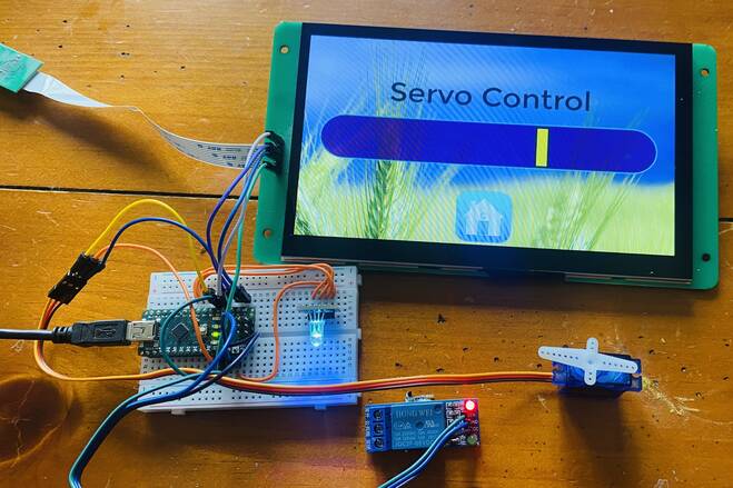
After the code is uploaded, you can start testing the entire system. The created UI looks like this and has the option to go into next page by clicking on Servo, LED and Relay.

Click on Servo first. You can slide the Servo Slider to control the Servo Rotation.
Go back to the homepage and click on RGB LED to enter into the next page. You can slide the Red, Green, Blue Slider to control the brightness and intensity of RGB Light. You can also mix colors to generate different color lights.

Go back to the homepage again. Click on Servo Control option from the display. In this mode you can select ON/OFF option to turn on or off the Relay Module.

Video Tutorial & Guide

You you want to display the sensor data on DWIN LCD Display and control Home Appliances you can follow the tutorial below.

The project is titled as DWIN Smart Home Controller and you can make it using ESP32.
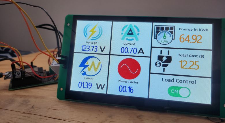
Similary, using the DWIN HMI LCD Display, we can also build an AC Energy Meter project, which looks like this.

")


4 Comments
Hi,
I had a problem connecting the display to the same serial port as the default serial port. I had to create a new software serial port to make it work. Does anyone know why?
Hey. Hey,
I had a problem connecting the display to the same serial port as the default serial port. I had to create a new software serial port to make it work. Does anyone know why?
I love DWIN displays, they are amazing!
we work with them for years in our distribution in Brazil (https://victorvision.com.br/)
Try https://github.com/pervu/DWIN2_Display/tree/v1.0.2