

1. Introduction: Raspberry Pi Embedded System Development Kit
Raspberry Pi Embedded System Development Kit is a perfect product for learning or using raspberry. Based on raspberry pi zero, it has a 320*240 LCD with a touch for display and integrates a chip to process audio playing & recording. It also has been equipped with a speaker, a 3.5mm audio jack and two mics, and some common add-on functions for Pi such as the A/D and GPIO expansions. It uses an SPI display and hardware expansions such as Mic/Audio, to make it more suitable for embedded projects.

As one of the most successful open hardware platforms, Raspberry Pi has been widely used in plenty of applications. This Pi interface Hat could be very suitable to learn Raspberry Pi for beginners. Makerfabs provided many demos for raspberry to display, play, record, and so on. These demos are available for you to study easily. So, lets begin with Raspberry Pi Embedded System Development Kit.
2. Features
- Raspberry pi zero W, 1GHz single-core CPU, 512MB RAM, Micro USB OTG port, Mini HDMI port, CSI camera connector, wireless LAN, and Bluetooth
- 3.2inch display, 320×240, ili9341 driver with SPI
- Resistive touch screen, XPT2046 controller
- Speaker
- 3.5mm audio jack
- Stereo Codec with Class D Speaker Driver: WM8960
- MEMS Mic*2: AOS3729A-T42-NXC
- Hardware expandable: I2C port, GPIO port, UART port
- ADC port: ADS1115
- Type-C USB power or battery power
- Support chargeable and 1A Maximum charging current
- Overcharge and over-discharge protection
- Size: 94mm*80mm*24mm
3. Diagram & Parts Details
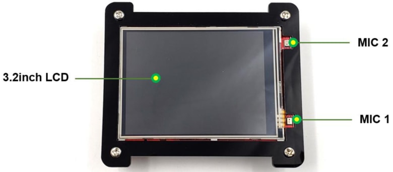
The board has 3.2 inch TFT LCD Display along with pair of mics on both sides.
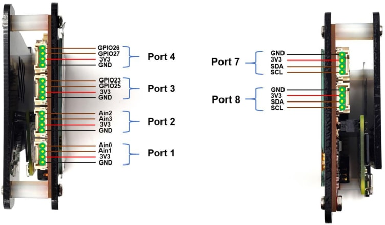
On the left and right sides there are ports named port1, port2, port3, port4, port7, and port8. It includes Power Pins, GIPO Pins, Analog Pins & I2C Pins.
On the front side it has port5 and port6 as Power, GPIO & UART Pins. In order to power the board, a Type C USB port is available. There is a power button to turn ON the module.

A Raspberry Pi Zero W Board is embedded in the kit which has a 16GB SD Card Storage. For Audio Input 3.5mm Audio Jack is available and for audio output, a Speaker is embedded on the board. You can power the board using 3.7V Lithium-Ion Battery or by using a Type C USB Power Supply.

4. Basic Usage
Start by opening the package of the product, press the button, and Pi interface Hat can be used normally. As the system power-up (Pi Zero required about one minute to start), it will show a short animation with audio.

Next, there are three options that will be shown and can be pressed to run the different programs respectively, then you can try some of the basic demos: testing screen, recording audio, and measuring temperature.
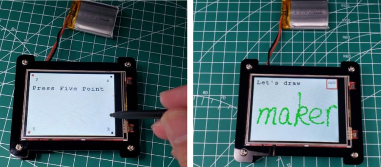
Touch Set
Click the black pixel one by one on the screen with your finger or touch screen pen, it is to calibrate the touch accuracy. The screen will flash a new page that you can touch or draw at will. Press the button at the top right to back to the options menu.
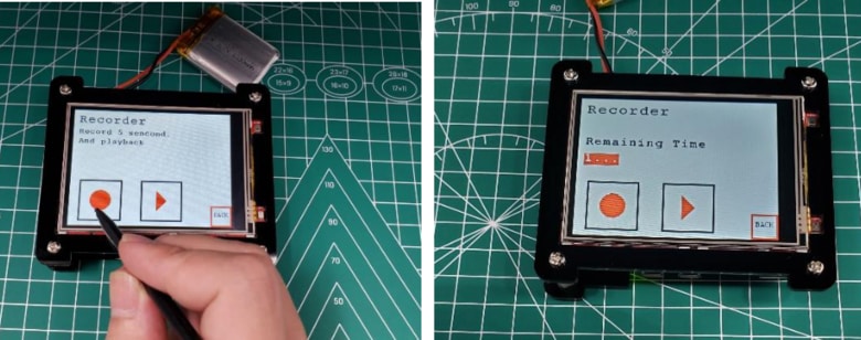
Record audio
Click the recording button at the left to start record audio with a length of 5 seconds. Click the play button at the right, the speaker will play the audio recorded.
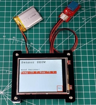
Measure temperature
Connect the Mabee_DHT11 module to the product Port 5 (GPIO 22), touch the measuring temperature button. The temperature and humidity will be display on the screen after a moment.
5. Connecting to Internet via WiFi
Before starting, you have to connect the raspberry to your WiFi.
Prepare a Software
A. SSH protocol
SSH or Secure Shell is a cryptographic network protocol for operating network services securely over an unsecured network. Typical applications include remote command-line, login, and remote command execution, but any network service can be secured with SSH.
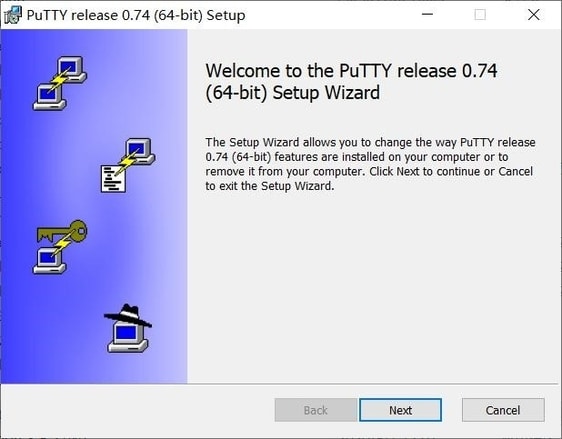
B. PuTTY tool
PuTTY is an SSH client, usually used to remotely control the Raspberry Pi. You can get the install package from here: https://www.putty.org/.
How to connect?
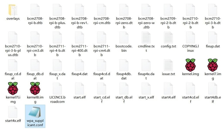
Remove the SD card from the raspberry pi and insert the SD card into the PC. Enter the SD card root, you will see some files in the root.
Create a new file to this root with the name “wpa_supplicant.conf”.
Open the new file wpa_supplicant.conf with text, and copy the following code to it. Fill in your WiFi SSID and password into the code instead of “***”. Then save the file and exit.
|
1 2 3 4 5 6 7 |
Country=CN ctrl_interface=DIR=/var/run/wpa_supplicant GROUP=netdev update_config=1 network={ ssid=”*****” psk=”****” key_mgmt=WPA-PSK priority=1 |
Set up a folder called SSH in the root, which is to turn on the Raspberry Pi SSH service.

Plug the SD card back into the Raspberry Pi, and power on the Pi Interface Hat again. Raspberry Pi will automatically connect to WIFI.
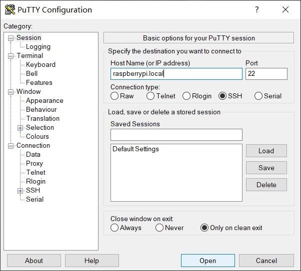
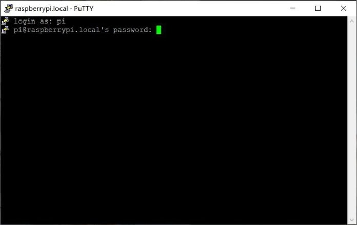
Make sure your computer and Raspberry Pi are on the same network. Open the Putty, enter “raspberrypi.local” in the address box, and click “open”.
Input the Raspberry Pi Username and password step by step.
Raspberry Pi Username: pi
The initial password for Raspberry Pi: raspberry
Note: It will not be displayed when entering a password and you have to complete it in one time.
Now input the command “ifconfig” in the terminal to check the Raspberry Pi IP.
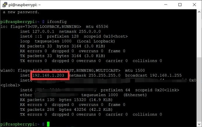
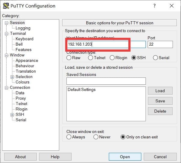
The WiFi connection is complete. You can use the IP to enter the Putty terminal next time, as follow.
6. Kill the process of default program.
Because of the default program (the 3 demos) started automatically, you have to kill the process to ensure the Pi is not in busy status, follow the steps to kill.
Enter the “top” command in the terminal, and find the id of the default program. In the top table, check the PID number which the COMMAND is “default_demo”, and the number is the process ID.
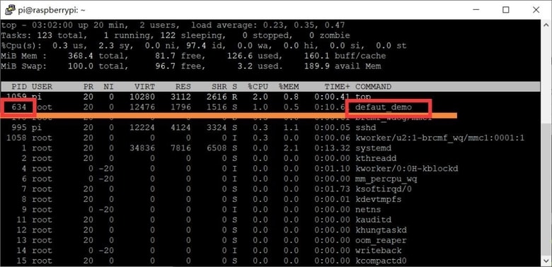
Click “Ctrl+C” to exit the top table.
Enter the below command to kill the process.
|
1 |
Sudo kill 634 |
7. Projects with Raspberry Pi Embedded System Development Kit
For learning further, Makerfabs provided multiple examples to show how to use. In many examples, additional programs need to be used instead of just Raspberry commands.
For convenience, we have loaded the project to the Raspberry, and the next chapter will show how to use them. The project covers all the programs for the demo, and it is necessary to follow the step to use the program for success.
1. Recode and Play
- Follow the steps to install the Linux kernel drivers for recording and playing (NOTE: If the Raspberry Pi OS is provided by Makerfabs, please ignore this step that the driver has been installed).
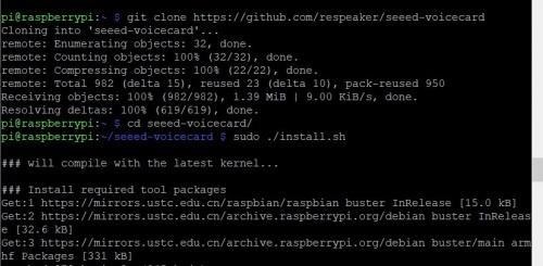
(Optional) Enter the following command in the Raspberry Pi terminal window to install the driver:
|
1 2 3 4 |
git clone https://github.com/respeaker/seeed-voicecard cd seeed-voicecard sudo ./install.sh sudo reboot |
Print the sound card list to see if the driver installation is successful.
|
1 |
Aplay -l |
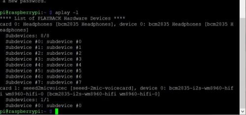
The “card 1” is the driver of the speakers and mics.
- Use the “alsamixer” command to enter the Interface to adjust the sound card volume. Press the F6 button to switch the sound card. As the figure, the “x1” is your sound card.

- Use the following command for voice recording. At the end of the recording, Raspberry Pi gets a two-channel wav file. Sometimes you have to change the number in the text “-Dhw:1,0” to “-Dhw:0,0”, “-Dhw:2,0” or any.
|
1 |
Arecord -c 2 -r 16000 -f S16_LE -Dhw:1,0 -d 3 temp.wav |
“-Dhw:1,0” means that sound card 1 is used for recording, “3” means that the recording time is 3s, and “temp.wav” is the file name which saved for recording.
- Use the following command to play audio.
|
1 |
aplay -Dhw:1,0 temp.wav |
“-Dhw:1,0” means that sound card 1 will be used for output, and “temp.wav” is the name of the output file.
Note1: the sound card can only support audio WAV-formatted and two-channel.
Note2: the volume is recommended to adjust to 80%, too strong is bad for playing. When it is powered by a battery, sometimes the unsteady voltage will cause the speaker to work not well.
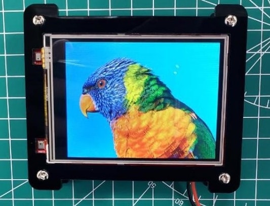
2. Display picture
- 3.2 inch LCD with driver ILI9341 is integrated on the board, and it is connected to Raspberry Pi zero with SPI, but not using the HDMI interface.
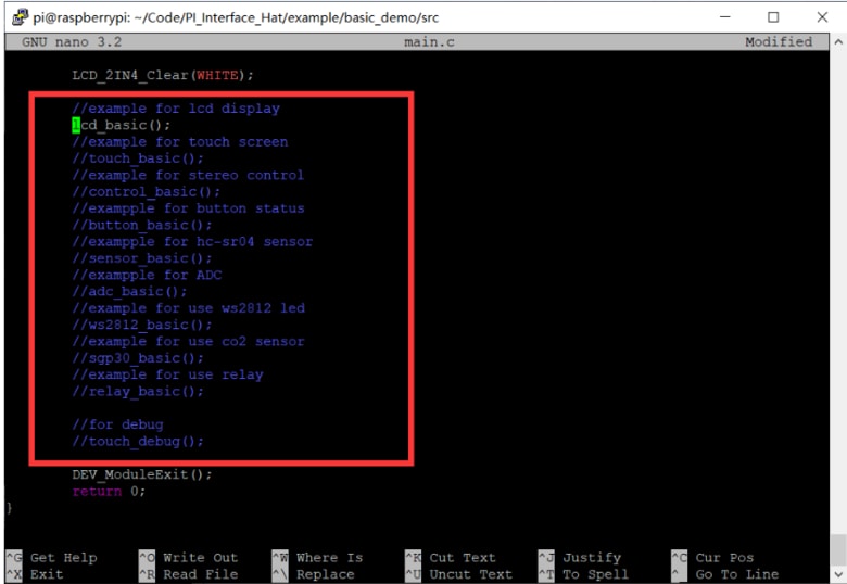
- Modify the code main.c. Uncomment the “lcd_basic()” function by deleting “//” before it, and comment out the other function by adding “//” before it, so there will be only the LCD_basic(); runs.
|
1 |
sudo nano main.c |
Click “Ctrl+o” and Enter to save, then click “Ctrl+x” to exit.
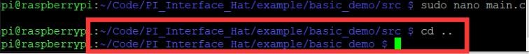
- Return directory to “/PI_Interface_Hat/example/basic_demo”.
|
1 |
Cd.. |
You can see the current location of the directory in the terminal.
- Run the command to compile the program.
|
1 |
make |
- Print a list of all files in the file directory, and check whether the executable file is added. Then execute it.
|
1 2 |
Ls sudo ./basic_demo |
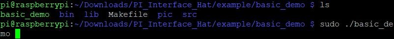
- The picture will be displayed on the screen.
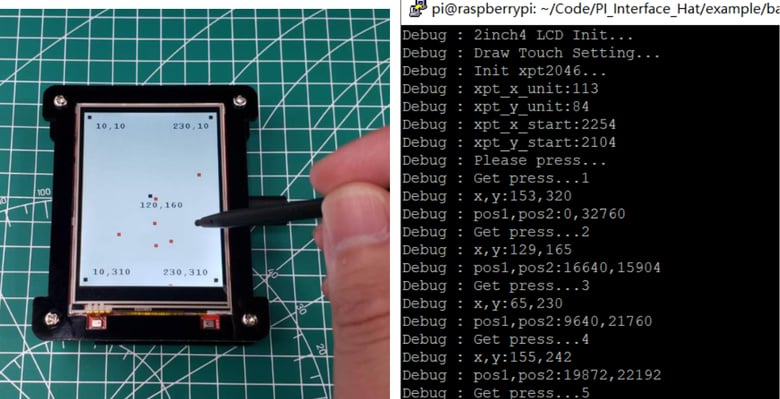
3. Touch screen
The LCD also has a touch panel with XPT2046. As the previous steps, change the directory to “~/Code/PI_Interface_Hat/example/basic_demo/src”, and modify the main.c to correct the function of the program. Uncomment “touch_basic()” as the figure shows.
|
1 2 |
cd ~/Code/PI_Interface_Hat/example/basic_demo/src sudo nano main.c |

- Change the directory to “~/Code/PI_Interface_Hat/example/basic_demo”, Run the command to compile the program.
|
1 2 |
cd .. make |
- Print a list of all files in the file directory, check whether the executable file is added, and execute it.
|
1 2 |
ls sudo ./basic_demo |
- The touch position will be displayed in the terminal of SSH when touch screen.
4. Get the ADC value
As you know, Raspberry Pi did not provide the ADC ability. Due to the Pi Interface Hat that had integrated ADS1115 chip, it has four channels ADC which the interfaces are Port 1 and Port 2. Blows we will have a try to A/D the input voltage signal.
- Connect the Potentiometer to port1.
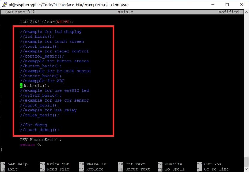
- As the above steps to modify and execute the code “main.c”. Uncomment the specified function in the main.c.
|
1 2 |
//exampple for ADC adc_basic(); |
- Follow the below step to execute the “make” command for verifying the program and run it.
|
1 2 3 |
cd ~/Code/PI_Interface_Hat/example/basic_demo make sudo ./basic_demo |
- The ADC value would be obtained and shown on the LCD.
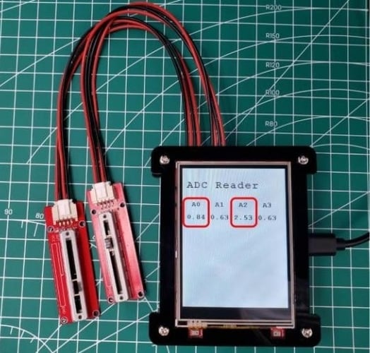
The detail of the code for getting the value from the ADC in the “/PI_Interface_Hat/example/basic_demo/src/adc_basic.c“.
|
1 2 3 4 5 6 7 8 9 10 11 12 13 14 15 16 17 18 19 20 21 |
int handle = wiringPiI2CSetup(ADS1115_ADDRESS); while (1) { float volts[4]; char value_str[80]; for (int i = 0; i < 4; ++i) { float v = readVoltage(handle, i, 0); if (v > 6) { v = 0; } volts[i] = v; } sprintf(value_str, "%4.2lf %4.2lf %4.2lf %4.2lf", volts[0], volts[1], volts[2], volts[3]); Paint_Clear(WHITE); Paint_DrawString_EN(10, 110, value_str, &Font16, WHITE, BLACK); LCD_2IN4_img(10, 110, 240, 130, (UBYTE *)BlackImage); } |
Display the value on the LCD.
|
1 2 |
Paint_Clear(WHITE); Paint_DrawString_EN(10, 110, value_str, &Font16, WHITE, BLACK); |
5. Monitor the button status
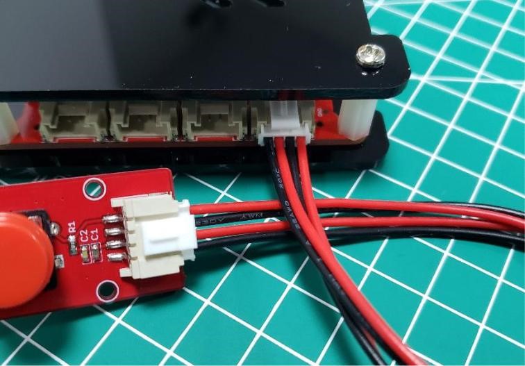
- Connect the BOTTON to the Port 4, that the signal wire is connected to GPIO26.
- As the above steps to modify and execute “main.c”, uncomment the content in the main.c.
|
1 2 |
//exampple for button status button_basic(); |
- Follow the below commands to run “make” step by step.
|
1 2 3 |
cd ~/Code/PI_Interface_Hat/example/basic_demo make sudo ./basic_demo |
- The demo code which read the value of button is “/PI_Interface_Hat/example/basic_demo/src/button_basic.c“. Get the value of the button:
|
1 2 |
int button_pin = 12; //GPIO 26 DEV_GPIO_Mode(button_pin, INPUT); |
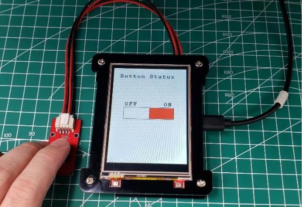
Display the button status on the LCD.
|
1 2 3 4 5 6 7 8 9 10 11 |
if (DEV_Digital_Read(button_pin) == LOW) { LCD_2IN4_FillRect(121, 141, 199, 178, WHITE); LCD_2IN4_FillRect(41, 141, 120, 178, BLACK); } else { LCD_2IN4_FillRect(41, 141, 120, 178, WHITE); LCD_2IN4_FillRect(121, 141, 199, 178, RED); } DEV_Delay_ms(100); |
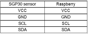
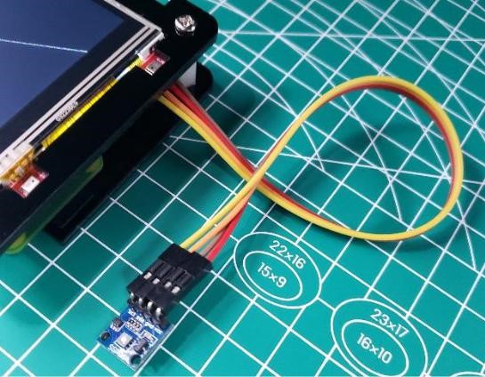
6. Get the CO2 level
- Pi Interface Hat provides two I2C interfaces which are Port 7 and Port 8. Connect the SGP30 sensor to the Port 7, the connection of the sensor is shown in the following figure.
- (Optional) You have to run the command to install the SGP30 library for driving. Again, if you use Makerfabs default OS in the Hat SD card, you do not need to do this as it is already installed.
|
1 |
sudo pip3 install pimoroni-sgp30 |
- (Optional) Install the package to support SGP30 library.
|
1 |
sudo pip3 install smbus2 |
- As the above steps to modify the code “main.c”. Uncomment the content of the SGP30 in the main.c.
|
1 2 |
//example for use co2 sensor sgp30_basic(); |
- Follow the below steps to run the “make” command.
|
1 2 3 |
cd .. make sudo ./basic_demo |
- The value would be shown in the raspberry terminal.
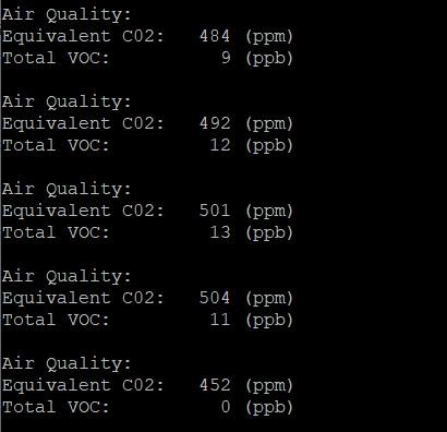
- The demo code for SGP30 to monitor is “/PI_Interface_Hat/example/basic_demo/py/sgp30_test.py” and is different from others. It was done in Python and would be run by Linux command.
Run the Linux command in /PI_Interface_Hat/example/basic_demo/src/sgp30_basic.c.
|
1 |
system("sudo python3 ./py/sgp30_test.py"); |
Initialize the SGP30 sensor in the python file /PI_Interface_Hat/example/basic_demo/py/sgp30_test.py.
|
1 2 |
sgp30 = SGP30() sgp30.start_measurement(crude_progress_bar) |
Get the CO2 level.
|
1 2 3 |
result = sgp30.get_air_quality() print(result) time.sleep(1.0) |
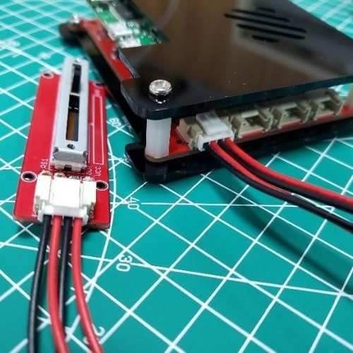
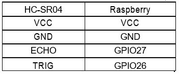
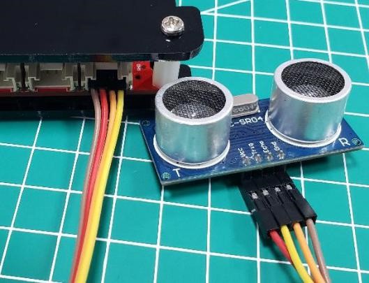
7. Use HC-SR04 to measure the distance
- Connect the HC-SR04 module to Port 4, the connection of the module is shown in following figure.
- As the above steps to modify and execute the code. Modify the code that uncomment special content in the main.c.
|
1 2 |
//exampple for hc-sr04 sensor sensor_basic(); |
- Follow the above tutorial to run the “make” command and execute the program.

- The detail of measuring the distance in the /PI_Interface_Hat/example/basic_demo/src/sensor_basic.c
|
1 2 3 4 5 6 7 8 9 10 11 12 13 14 15 16 17 18 19 20 21 22 23 24 25 26 |
unsigned int begin_time = micros(); // Wait for ping response, or timeout. while (digitalRead(ECHO) == LOW && micros() - begin_time < timeout) { } // Cancel on timeout. if (micros() - begin_time > timeout) { printf("1.Out of range.\n"); return 0; } ping = micros(); // Wait for pong response, or timeout. while (digitalRead(ECHO) == HIGH && micros() - ping < timeout) { //printf("ECHO HIGH\n"); } // Cancel on timeout. if (micros() - ping > timeout) { printf("2.Out of range.\n"); return 0; } pong = micros(); // Convert ping duration to distance. distance = (int)((pong - ping) * 0.017150); printf("Distance: %.d cm.\n", distance); |
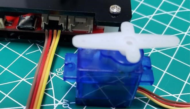
8. Control the servo
- The mini servo has three pins, the red one is VCC, the brown is GND, and the yellow is signal. The servo can be controlled by a PWM signal. Connect the signal pin of the servo to Ports 5(GPIO21 in hardware).
- Uncomment the content in the main.c of the project as above instruction.
|
1 2 |
//example for stereo control control_basic(); |
- In order to drive the servo successfully, you have to check the signal pin used in the code “/src/control_basic.c”. Use the command to open the code “control_basic.c”.
|
1 |
sudo nano control_basic.c |
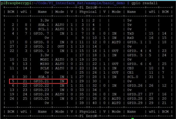
Note: to change the port code to 5, as it uses the BCM2835 library which is a C library for Raspberry to provide access to GPIO and other IO functions on the Broadcom BCM 2835 chip, and the GPIO21 is coded to “5” in the BCM:
|
1 2 3 4 5 |
…… servo_init(5); servo_angle(5, 0); …… servo_angle(5, angle); |
Click “Ctrl+o” and Enter to save then click “Ctrl+x” to exit.
- Follow the below steps to run the “make” command for verify the program.
|
1 2 3 |
cd ~/Code/PI_Interface_Hat/example/basic_demo make sudo ./basic_demo |
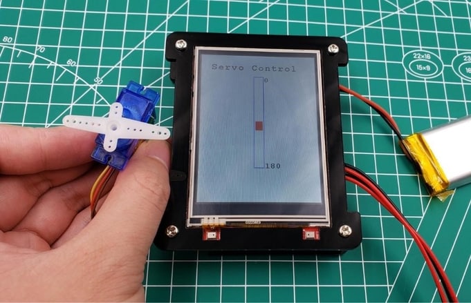
- The control button will be displayed on the LCD. Touch the screen to drive the servo running.
9. Control the WS2812 LEDs
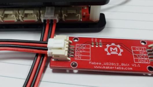
- Connect WS2812 LEDs to the Port 3. The signal pin which controlled the WS2812 LEDs is connected to IO23.
- (Optional) There is no library that support WS2812 and you have to run the command to install the WS2812 library.
|
1 |
sudo pip install rpi_ws281x |
- Uncomment the content in the main.c of the project.
|
1 2 |
//example for use ws2812 led ws2812_basic(); |
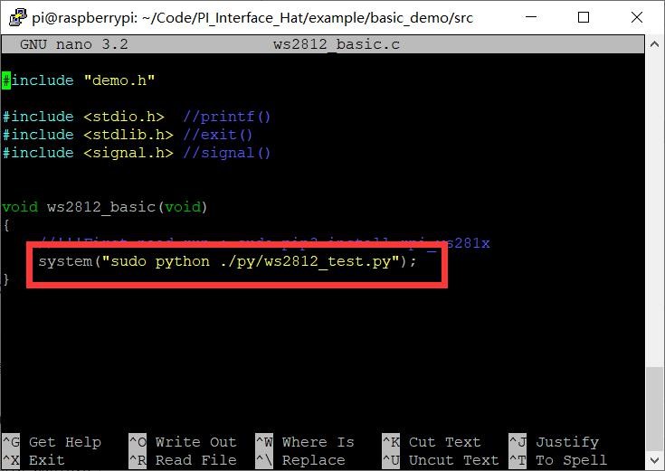
- Open “ws2812_basic.c” by:
|
1 |
sudo nano ws2812_basic.c |
Modify the code to “sudo python ./py/ws2812_test.py”, the final such as the picture.
- Follow the steps to verify the program and execute it.
|
1 2 3 |
cd ~/Code/ PI_Interface_Hat/example/basic_demo make sudo ./basic_demo |
- The demo code for WS2812 is /basic_demo/py/ws2812_test.py. The LED configuration:
|
1 2 3 4 5 6 7 8 |
# LED strip configuration: LED_COUNT = 12 # Number of LED pixels. LED_FREQ_HZ = 800000 # LED signal frequency in hertz (usually 800khz) LED_DMA = 10 # DMA channel to use for generating signal (try 10) LED_BRIGHTNESS = 50 # Set to 0 for darkest and 255 for brightest # True to invert the signal (when using NPN transistor level shift) LED_INVERT = False LED_CHANNEL = 1 # set to '1' for GPIOs 13, 19, 41, 45 or 53 LED_PIN = 13 # BCM13 / GPIO23 |
Initialize the ws2812:
|
1 2 3 |
strip = Adafruit_NeoPixel(LED_COUNT, LED_PIN, LED_FREQ_HZ, LED_DMA, LED_INVERT, LED_BRIGHTNESS, LED_CHANNEL) strip.begin() |
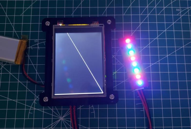
Turn the LED on:
|
1 2 3 |
for x in range(0, LED_COUNT): strip.setPixelColor(x, Color(255, 0, 0)) strip.show() |
This is how we can get started with Raspberry Pi Embedded System Development Kit for Beginners. Apart from the demo projects, you can other thousands of projects using this Raspberry Pi Embedded System Development Kit.


