

Overview
In this comprehensive guide, we will explore the process of integrating an ADS1115 16-bit ADC module with the Raspberry Pi, a renowned single-board computer developed by the Raspberry Pi Foundation. The ADS1115 breakout board is a high-resolution analog-to-digital converter (ADC) that can be used in conjunction with microcontrollers and single-board computers such as Arduino, ESP8266/32, STM32, and of course, the Raspberry Pi.
While the Raspberry Pi provides a multitude of digital I/O pins, it lacks a built-in ADC, which means it cannot directly read analog signals. This can be a limitation for projects that require the interfacing of sensors or devices that output analog signals. By incorporating the ADS1115 module, which boasts a 16-bit ADC resolution, the Raspberry Pi’s ability to handle analog inputs can be vastly expanded. With the ADS1115, the smallest voltage that can be measured is 5V / 65536 = 0.000076V (76uV), offering enhanced precision for your projects. If you want more precison up to 0.3uV, you may check ADS1220 24-Bit ADC Module.
In the tutorial, we will take a look into the specifications and benefits of the ADS1115 module, illustrate the necessary components and connections for interfacing it with the Raspberry Pi, and furnish a sample Python code to assist you in initiating this potent ADC enhancement.
Bill of Materials
To thoroughly understand the ADS1115 ADC Module when used with Raspberry Pi, we require the following components:
| S.N. | Components | Quantity | Purchase Link |
|---|---|---|---|
| 1 | Raspberry Pi 4 | 1 | Amazon | AliExpress |
| 2 | ADS1115 ADC Module | 1 | Amazon | AliExpress |
| 3 | 10K Potentiometer | 1 | Amazon | AliExpress |
| 4 | Breadboard | 1 | Amazon | AliExpress |
| 5 | Connecting Wires | 10 | Amazon | AliExpress |
ADS1115 Chip
The ADS1115 is a precision, low-power, 16-bit, I2Ccompatible, analog-to-digital converter IC.

Features of ADS1115
- 16-bit Resolution
- Four (4) Channel Single-Ended or Two (2) Channel Differential Inputs
- I2C Protocol Interface
- Programmable Comparator
- Wide Supply Range
- Low Current Consumption
- Continuous-Conversion Mode
- Programmable Data Rate
- Programmable Comparator
- Single-Cycle Settling
- Internal Low-Drift Voltage Reference
- Internal Oscillator
- Wide Operating Temperature Range
- Available in Ultra-Small X2QFN Package
ADS1115 Pin Configuration
The below image shows the pin configuration of the ADS1115 chip.

- Pin 1 is the ADDR pin that selects the I2C address for the chip.
- Pin 2 is the Alert/Ready pin which serves as a data ready and alert signal.
- Pin 3 is the GND terminal.
- Pins 4, 5, 6 & 7 are the four (4) ADC input pins. We can use these pins as either four (4) single-ended inputs or two (2) differential inputs.
- Pin 8 is the positive power supply pin which accepts 2.0 V to 5.5 V
- Pins 9 and 10 are the terminals for the I2C interface, SDA and SCL respectively.
ADS1115 Functional Block Diagram
The below is the functional diagram for the ADS1115 Chip.

Initially a multiplexer selects the input signal. Then, the selected signal feeds into a Programmable Gain amplifier (PGA). The PGA can be programmed to provide amplification of small signals prior to conversion.
Subsequently, the input is converted by a 16-bit Delta Sigma converter. The converter uses its own built-in voltage reference and built-in oscillator in measuring the input signal. Finally, the result of the conversion goes into the I2C interface. Also, a comparator provides a signal to the external interface that the result is ready for fetching.
Typical Connections of the ADS1115
The principle I2C connections for the ADS1115 is shown in the image below.

The ADS1115 interfaces directly to standard mode, fast mode, and high-speed mode I2C controllers. Any microcontroller I2C peripheral, including master-only and single-master I2C peripherals, operates with the ADS1115.
For more information refer to ADS1115 Datasheet
ADS1115 Module or Breakout Board
The ADS1115 comes with X2QFN & VSSOP package which can’t be used for prototyping. Therefore we need the ADS1115 Module or Breakout Board to use it with Raspberry Pi or Any other Microcontroller.

These modules are widely available from different manufacturers and are very inexpensive. They are breadboard friendly and can be easily used in prototyping and testing applications.
ADS1115 Module Pinout
The ADS1115 Module has a total number of 10 Pins.
| Pin. No. | Pin Name | Pin Description |
| 1 | VDD | Power supply: 2.0V to 5.5V |
| 2 | GND | Ground |
| 3 | SCL | Serial clock input: Clocks data on SDA (used for I2C communication) |
| 4 | SDA | Serial data: Transmits and receives data (used for I2C communication) |
| 5 | ADDR | I2C address select (slave) |
| 6 | ALERT/RDY | Digital comparator output or conversion ready |
| 7 | AIN0 | Differential channel 1: Single-ended channel 1 input or Negative input |
| 8 | AIN1 | Differential channel 1: Single-ended channel 2 input or Negative input |
| 9 | AIN2 | Differential channel 2: Single-ended channel 3 input or Positive input |
| 10 | AIN3 | Differential channel 2: Single-ended channel 4 input or Negative input |
ADS1115 Module Schematic
The schematic diagram shown above is Adafruit’s version of the ADS1115 module.

It follows the typical connection for the ADS1115 chip. The 10K ohms pull-up resistors are installed on the I2C and Alert pins. Also, there is a 1uF capacitor installed between the VDD pin and the GND which serves as a decoupling capacitor.
Interfacing ADS1115 Module with Raspberry Pi
Interfacing an ADS1115 module with a Raspberry Pi 4 is straightforward, as both devices use the I2C communication protocol. In this tutorial, we will guide you through the steps to connect and configure the ADS1115 with the Raspberry Pi 4.

- Connect the VCC pin of the ADS1115 to the 3.3V pin of the Raspberry Pi.
- Connect the GND pin of the ADS1115 to any GND pin on the Raspberry Pi.
- Connect the SDA pin of the ADS1115 to the SDA pin of the Raspberry Pi.
- Connect the SCL pin of the ADS1115 to the SCL pin of the Raspberry Pi.

You may connect the A0, A1, A2, and A3 pins of the ADS1115 to the sensors or devices whose analog values you want to read. In this example, we will use a 10K Potentiometer that can be connected to A0 Pin of ADS1115.
ADS1115 Python Library Installation
Before moving to the Python programming part, we need to install ADS1115 Library on Raspberry Pi.
Open a terminal window on your Raspberry Pi. Run the following command to install the ADS1x15 Python library.
|
1 |
sudo pip3 install adafruit-circuitpython-ads1x15 |
Python Code to Read Analog Value using ADS1115 & Raspberry Pi
Here is the Python Code to interface ADS1115 16-bit ADC Module with Raspberry Pi. The code will read analog value from Pin A0 fed using the potentiometer. You may use a ADC Calculator to manually calculate the ADC Value.
Copy the following code and paste it on the Thonny IDE editor window.
|
1 2 3 4 5 6 7 8 9 10 11 12 13 14 15 16 17 18 19 |
import board import time import busio import adafruit_ads1x15.ads1115 as ADS from adafruit_ads1x15.analog_in import AnalogIn # Initialize the I2C interface i2c = busio.I2C(board.SCL, board.SDA) # Create an ADS1115 object ads = ADS.ADS1115(i2c) # Define the analog input channel channel = AnalogIn(ads, ADS.P0) # Loop to read the analog input continuously while True: print("Analog Value: ", channel.value, "Voltage: ", channel.voltage) time.sleep(0.2) |
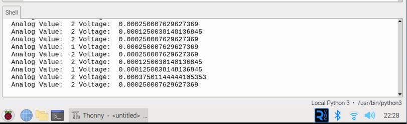
Run the Code and you can see the following readings in Thonny Shell.
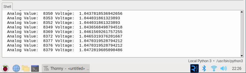
If the potentiometer is rotated to full position, the Thonny Shell shows 3.3V as full voltage.
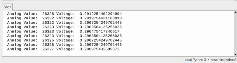
If the potentiometer is rotated to zero position, the Thonny Shell shows 0V as voltage.
Python Code to Read Multiple Analog Values
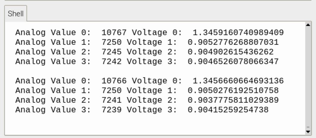
The ADS1115 has 4 channel input. Hence, it can read 4 different analog values at the same time.
The following Python Code will read the multiple analog values from 4 different ADC pins A0, A1, A2, A3.
|
1 2 3 4 5 6 7 8 9 10 11 12 13 14 15 16 17 18 19 20 21 22 23 24 25 26 27 |
import board import busio import adafruit_ads1x15.ads1115 as ADS from adafruit_ads1x15.analog_in import AnalogIn import time # Initialize the I2C interface i2c = busio.I2C(board.SCL, board.SDA) # Create an ADS1115 object ads = ADS.ADS1115(i2c) # Define the analog input channels channel0 = AnalogIn(ads, ADS.P0) channel1 = AnalogIn(ads, ADS.P1) channel2 = AnalogIn(ads, ADS.P2) channel3 = AnalogIn(ads, ADS.P3) # Loop to read the analog inputs continuously while True: print("Analog Value 0: ", channel0.value, "Voltage 0: ", channel0.voltage) print("Analog Value 1: ", channel1.value, "Voltage 1: ", channel1.voltage) print("Analog Value 2: ", channel2.value, "Voltage 2: ", channel2.voltage) print("Analog Value 3: ", channel3.value, "Voltage 3: ", channel3.voltage) # Delay for 1 second time.sleep(1) |
Run the Python Code and the Thonny Shell will show the reading of 4 analog input.
Conclusion
This guide explains how to connect the ADS1115 to the Raspberry Pi, showing its features and benefits. Armed with this knowledge and the provided sample Python code, users are well-equipped to significantly enhance the Raspberry Pi’s prowess in handling analog signals, paving the way for more intricate and precision-oriented projects.


3 Comments
Following your tutorial I’m getting “No Hardware I2C on (scl,sda)=(3, 2)”. Your tutorial is missing one very important detail. We need to enable I2C connection on the device:
It costed me a day of troubleshooting and trying to figure out what I did wrong: checking installed libraries, python version, wiring, voltage on ADS, etc. When I didn’t do anything wrong. The tutorials are missing the fact that you have to first enable the I2C on the device.
I still haven’t fixed the issue(no physical access to the device at the moment), but I bet this is the problem. And even if it isn’t, you’re still missing it and it still won’t work, unless you actually enable it yourself, because it’s disabled by default on new RPi devices.
Hi, I’m interested to get your help to a project. I saw you are on a platform for that purpose.
Please mail us: [email protected]