

Overview
In this guide, we’ll learn how to connect the ADXL345 accelerometer to the Raspberry Pi and measure acceleration using Python. The Raspberry Pi is a small, powerful computer, and the ADXL345 is a sensor that can detect motion. When combined, they make a great pair for all sorts of fun projects like motion alarms or interactive games.
We’ll walk through the steps to connect the two devices, then show you how to write simple Python code to read data from the accelerometer. By the end, you’ll know how to use the Raspberry Pi 4 and ADXL345 together and be ready to start your own projects.
Components Required
We need the following components for this guide.
| S.N. | Components | Quantity | Purchase Link |
|---|---|---|---|
| 1 | Raspberry Pi | 1 | Amazon | AliExpress | SunFounder |
| 2 | ADXL345 3-Axis Accelerometer | 1 | Amazon | AliExpress | SunFounder |
| 3 | Breadboard | 1 | Amazon | AliExpress | SunFounder |
| 4 | Connecting Wires | 5 | Amazon | AliExpress | SunFounder |
ADXL345 Digital Acccelerometer
The ADXL345 is a 3-axis accelerometer developed by Analog Devices. This sensor is designed to accurately measure acceleration in the X, Y, and Z axes, making it suitable for various applications. It is particularly popular in the fields of robotics, gaming, virtual reality, wearables, and IoT devices, among others.

This accelerometer is capable of detecting both static acceleration, such as the force of gravity, and dynamic acceleration resulting from motion or vibrations. The ADXL345 has adjustable sensitivity, enabling it to cater to a range of applications with different acceleration requirements.
The ADXL345 communicates with microcontrollers using either I2C or SPI interfaces, which makes it compatible with a wide range of development platforms, such as Arduino, Raspberry Pi , and others. Thanks to its low power consumption and small form factor, the ADXL345 is ideal for battery-powered and space-constrained applications.
Specifications of ADXL345
The ADXL345 is a triple-axis accelerometer with the following key specifications:
- Axes: 3-axis (X, Y, Z)
- Sensitivity: User-selectable, ±2g, ±4g, ±8g, or ±16g
- Resolution: 10-bit or 13-bit, user-selectable
- Output data rate (ODR): 0.10 Hz to 3200 Hz
- Communication interfaces: I2C (up to 400 kHz) and SPI (4-wire and 3-wire, up to 5 MHz)
- Supply voltage range: 2.0 V to 3.6 V
- Current consumption: 23 µA to 130 µA, depending on output data rate and measurement mode
- Operating temperature range: -40°C to +85°C
- Package: 3 mm × 5 mm × 1 mm LGA
Pinout of ADXL345
The ADXL345 3-axis Digital Accelerometer Module has 8 pins.

- GND: Ground connection for the module.
- VCC: Power supply input, typically 3.3V, but it can accept a voltage range from 2.0V to 3.6V
- CS (Chip Select): Used for SPI communication. When pulled low, it enables SPI communication; when pulled high, it switches to I2C communication.
- INT1 (Interrupt 1): This pin can be configured to output interrupt signals for certain events like activity/inactivity detection, single/double-tap detection, or free-fall detection.
- INT2 (Interrupt 2): This pin can be configured to output interrupt signals for certain events like activity/inactivity detection, single/double-tap detection, or free-fall detection.
- SDO (Serial Data Out): Master In Slave Out (MISO) line for SPI communication.
- SDA (Serial Data): Serial Data (I2C)/Serial Data Input (SPI 4-Wire)/Serial Data Input and Output (SPI 3-Wire).
- SCL (Serial Clock): Serial Communications Clock. SCL is the clock for I2C, and SCLK is the clock for SPI.
Interfacing ADXL345 Accelerometer with Raspberry Pi 4
To use the ADXL345 accelerometer with a Raspberry Pi 4 using Python, you’ll need to make the necessary hardware connections and then write a Python script to communicate with the sensor. Let’s start by understanding the connection procedure. Follow the steps below to connect the accelerometer to your Raspberry Pi 4.

Connect the ADXL345 to the Raspberry Pi Pico as follows:
- VCC from ADXL345 to 3.3V on Raspberry Pi 4 (Pin 1)
- GND from ADXL345 to GND on Raspberry Pi 4 (Pin 6)
- SDA from ADXL345 to SDA (GPIO 2, Pin 3) on Raspberry Pi 4
- SCL from ADXL345 to SCL (GPIO 3, Pin 5) on Raspberry Pi 4

Python Code for Measuring Acceleration & Tilt Angles
Now lets write a Python Code to interface ADXL345 with Raspberry 4 and measure Acceleration in X, Y, Z axis as well as Tilt Angles. We haven’t used any library for this code. You need to enable I2C Communication first to use this code.
This Python script is for interfacing with the ADXL345 accelerometer using the I2C communication protocol. The ADXL345 is a 3-axis accelerometer, and this script allows you to read acceleration data from it and calculate the tilt angles (pitch and roll) based on the acceleration values.
Copy the following code and paste it on your Thonny IDE Editor Window.
|
1 2 3 4 5 6 7 8 9 10 11 12 13 14 15 16 17 18 19 20 21 22 23 24 25 26 27 28 29 30 31 32 33 34 35 36 37 38 39 40 41 42 43 44 45 46 47 48 49 50 51 52 53 54 55 56 57 58 59 60 61 62 63 64 65 |
import smbus import time import math # ADXL345 I2C Address ADXL345_I2C_ADDR = 0x53 # ADXL345 Registers POWER_CTL = 0x2D DATA_FORMAT = 0x31 DATAX0 = 0x32 DATAX1 = 0x33 DATAY0 = 0x34 DATAY1 = 0x35 DATAZ0 = 0x36 DATAZ1 = 0x37 class ADXL345: G = 9.81 # Earth's gravity in m/s^2 def __init__(self, bus_num=1): self.bus = smbus.SMBus(bus_num) # Set range to +/- 16g and FULL_RES bit self.bus.write_byte_data(ADXL345_I2C_ADDR, DATA_FORMAT, 0x0B) # Turn on the accelerometer self.bus.write_byte_data(ADXL345_I2C_ADDR, POWER_CTL, 0x08) def read_acceleration(self): # Read acceleration data bytes = self.bus.read_i2c_block_data(ADXL345_I2C_ADDR, DATAX0, 6) # Convert to 2's complement and then to m/s^2 x = (bytes[1] << 8 | bytes[0]) if x & (1 << 15): x = x - (1 << 16) x = (x / (2**15)) * 16 * self.G y = (bytes[3] << 8 | bytes[2]) if y & (1 << 15): y = y - (1 << 16) y = (y / (2**15)) * 16 * self.G z = (bytes[5] << 8 | bytes[4]) if z & (1 << 15): z = z - (1 << 16) z = (z / (2**15)) * 16 * self.G return (x, y, z) def get_tilt_angles(self): x, y, z = self.read_acceleration() pitch = math.degrees(math.atan2(y, math.sqrt(x**2 + z**2))) roll = math.degrees(math.atan2(-x, z)) return pitch, roll if __name__ == "__main__": accelerometer = ADXL345() while True: x, y, z = accelerometer.read_acceleration() pitch, roll = accelerometer.get_tilt_angles() print(f"Acceleration - X: {x:.3f} m/s^2, Y: {y:.3f} m/s^2, Z: {z:.3f} m/s^2") print(f"Pitch: {pitch:.2f}°, Roll: {roll:.2f}°") time.sleep(0.5) |
Code Explanation
|
1 2 3 |
import smbus import time import math |
These lines import three Python modules:
smbus: Provides functions to communicate with devices over I2C, a communication protocol.time: Used for various time-related tasks. In this code, specifically for introducing delays.math: Provides access to mathematical functions. Here, it’s used for trigonometry and angle conversion.
|
1 2 3 4 5 6 7 8 |
# ADXL345 I2C Address ADXL345_I2C_ADDR = 0x53 # ADXL345 Registers POWER_CTL = 0x2D DATA_FORMAT = 0x31 DATAX0 = 0x32 ... |
This section defines constants:
ADXL345_I2C_ADDR: The I2C address of the ADXL345 accelerometer.- The next lines (like
POWER_CTL,DATA_FORMAT, etc.) are register addresses within the ADXL345 device. These registers store configurations and data. For instance,POWER_CTLis the address for the power control register, which can be used to turn the accelerometer on/off.
|
1 2 |
class ADXL345: G = 9.81 # Earth's gravity in m/s^2 |
This line starts the definition of a class called ADXL345. Within this class, a constant G representing Earth’s gravitational force (9.81 m/s^2) is defined. This constant will be used later for acceleration calculations.
|
1 2 3 4 5 6 |
def __init__(self, bus_num=1): self.bus = smbus.SMBus(bus_num) # Set range to +/- 16g and FULL_RES bit self.bus.write_byte_data(ADXL345_I2C_ADDR, DATA_FORMAT, 0x0B) # Turn on the accelerometer self.bus.write_byte_data(ADXL345_I2C_ADDR, POWER_CTL, 0x08) |
The __init__ function is a constructor, which gets automatically called when an object of the ADXL345 class is created. Here, it initializes the I2C bus for communication and sends commands to the accelerometer:
- Setting its range to ±16g and setting the FULL_RES bit.
- Turning on the accelerometer.
|
1 |
bytes = self.bus.read_i2c_block_data(ADXL345_I2C_ADDR, DATAX0, 6) |
This line reads 6 bytes of data starting from the DATAX0 register. These bytes contain acceleration values for the X, Y, and Z axes.
|
1 2 3 4 |
x = (bytes[1] << 8 | bytes[0]) if x & (1 << 15): x = x - (1 << 16) x = (x / (2**15)) * 16 * self.G |
Here, the 2 bytes corresponding to the X-axis acceleration are combined to form a 16-bit number. The acceleration values are represented in 2’s complement, so there’s a check and conversion for negative values. Then, the value is scaled to get acceleration in m/s^2.
|
1 2 |
pitch = math.degrees(math.atan2(y, math.sqrt(x**2 + z**2))) roll = math.degrees(math.atan2(-x, z)) |
This section calculates the pitch and roll angles from the acceleration values using trigonometric relationships.
|
1 2 3 4 5 6 7 8 |
if __name__ == "__main__": accelerometer = ADXL345() while True: x, y, z = accelerometer.read_acceleration() pitch, roll = accelerometer.get_tilt_angles() print(f"Acceleration - X: {x:.3f} m/s^2, Y: {y:.3f} m/s^2, Z: {z:.3f} m/s^2") print(f"Pitch: {pitch:.2f}°, Roll: {roll:.2f}°") time.sleep(0.5) |
If the script is run as the main program, it enters this loop:
- An ADXL345 object is created.
- It then continually reads acceleration values and calculates tilt angles.
- These values are printed out every 0.5 seconds.
Testing & Results
Save the Python Code with any name. Then hit the Run Button.
In the Thonny Shell, you will see the value of Acceleration in X, Y, Z Axis in unit of m/s^2. You will also see the values of Pitch and Roll in degrees.
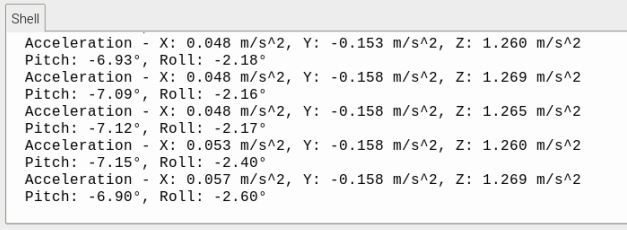
To observe the change in the values, you can rotate or tilt the accelerometer.
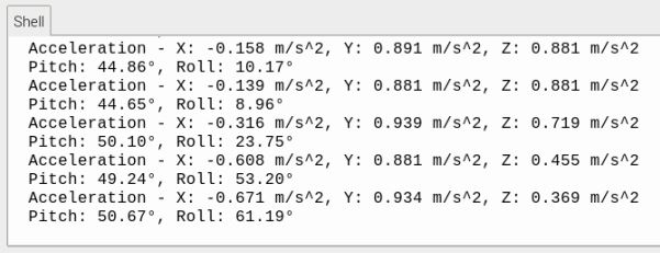
In this reading, it is observed that the yaw value is not calculated.
To calculate yaw using only an accelerometer like ADXL345 isn’t directly feasible. The reason is that yaw is a rotation about the vertical (gravity) axis, and an accelerometer measures linear acceleration. Without a reference (like magnetic North from a magnetometer or compass), there’s no change in gravitational force on the sensors to determine the yaw angle.
Hence using the ADXL345 3-axis Accelerometer, you can calculate Acceleration in X, Y, Z axis and also measure the Pitch and Roll Values.


