

Overview
In this tutorial, we will explore how to connect the HMC5883L Triple Axis Digital Magnetometer to a Raspberry Pi and harness its capabilities using Python. The HMC5883L stands out as an optimal choice for digital compass applications, thanks to its three-dimensional magnetometer features that allow for precise measurements of magnetic field strength and orientation. This makes it an invaluable tool for pinpointing the Earth’s magnetic north.
Upon integrating the HMC5883L magnetometer with the Raspberry Pi, we will be able to fetch compass readings and ascertain the magnetic field across the X, Y, and Z axes in terms of microteslas (µT). From this data, determining the heading in degrees becomes a straightforward computation. We’ll be guiding you through every step of the process, ensuring you can seamlessly execute these tasks with Python on your Raspberry Pi.
Bill of Materials
We need following components to work on this project.
| S.N. | Components | Quantity | Purchase Link |
|---|---|---|---|
| 1 | Raspberry Pi 4 | 1 | Amazon | AliExpress | SunFounder |
| 2 | HMC5883L Magnetometer | 1 | Amazon | AliExpress | SunFounder |
| 3 | Jumper Wires | 10 | Amazon | AliExpress | SunFounder |
| 4 | Breadboard | 1 | Amazon | AliExpress | SunFounder |
HMC5883L 3-Axis Compass/Magnetometer
The HMC5883L is a digital compass conceived by Honeywell. It is a surface-mount, multi-chip module engineered specifically for the detection of low magnetic fields. It is particularly adept at supplying directional data, making it a common choice for navigation and positioning systems.
The design of the HMC5883L revolves around anisotropic magnetoresistive (AMR) technology, which facilitates the precise measurement of magnetic fields. It includes three-axis sensors, with field capacities spanning from ±1.3 to ±8.1 Gauss. This denotes its capability to measure magnetic fields across three distinct axes (X, Y, and Z), allowing it to sense the direction of the Earth’s magnetic field in a three-dimensional context.
The HMC5883L is equipped with numerous inherent features that simplify its incorporation into a variety of systems. Among these are an integrated ADC (Analog-to-Digital Converter) offering 12-bit data output, and an I2C serial bus interface. This interface is utilized for device communication, enabling it to transfer data to a microcontroller or another processing unit.
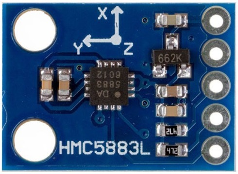
The HMC5883L Magnetometer Module is comprised of an HMC5883L Magnetometer IC, a Voltage Regulator IC, resistors, and capacitors, all consolidated within an integrated circuit. It uses a voltage regulator IC XC6206P332MR (662K).
Refer to HMC5883L datsheets to learn more: Download HMC5883L Datasheet
Specifications of HMC5883L
- Operating Voltage: 3V to 6V DC
- Operating Current: 100-130 μA
- I2C interface
- 1-2 degree heading accuracy
- Integrated 12-bit ADC
- 160Hz max data rate
- Range of -8 to +8 Gauss
- Data Output Rate: 0.75, 1.5, 3, 7.5, 15 Hz
Pinout of HMC5883L
The HMC5883L module has five pins as shown in this image below:
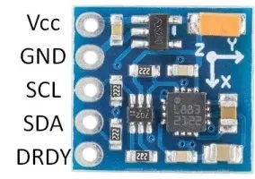
Here is a basic description of the typical pinout for an HMC5883L module.
- VCC: This is the power supply pin. It requires a DC voltage, typically 3V -6V.
- GND: This is the ground pin.
- SCL: This is the clock line for the I2C interface.
- SDA: This is the data line for the I2C interface.
- DRDY: This is Data Ready pin which goes low when new data is available. It’s optional and isn’t always used in basic applications.
Register Mapping & I2C Communication
| Register Address | Name | Access |
|---|---|---|
| 00 | Configuration Register A | Read/Write |
| 01 | Configuration Register B | Read/Write |
| 02 | Mode Register | Read/Write |
| 03 | Data Output X MSB Register | Read |
| 04 | Data Output X LSB Register | Read |
| 05 | Data Output Z MSB Register | Read |
| 06 | Data Output Z LSB Register | Read |
| 07 | Data Output Y MSB Register | Read |
| 08 | Data Output Y LSB Register | Read |
| 09 | Status Register | Read |
| 10 | Identification Register A | Read |
| 11 | Identification Register B | Read |
| 12 | Identification Register C | Read |
The HMC5883L magnetometer uses various internal registers to configure and receive data:
- Configuration Register A (0x00): Configures device operation, including output data rate and measurement configuration.
- Configuration Register B (0x01): Sets the device gain and sensitivity.
- Mode Register (0x02): Selects the operating mode, such as continuous measurement, single measurement, or idle mode.
- Data Output X Registers (0x03 and 0x04): Hold X-axis sensor readings.
- Data Output Y Registers (0x05 and 0x06): Hold Y-axis sensor readings.
- Data Output Z Registers (0x07 and 0x08): Hold Z-axis sensor readings.
- Status Register (0x09): Contains status flags about data output.
- Identification Registers (0x0A, 0x0B, 0x0C): Used to identify the device.
The HMC5883L employs the I2C communication protocol, functioning as a slave device. Its designated I2C device address is 0x1E. The corresponding addresses for its read and write operations are as follows:
- For write operations (SLA+W), the address is 0x3C.
- For read operations (SLA+R), the address is 0x3D.
Interfacing HMC5883L Magnetometer with Raspberry Pi Pico
Let us interface the HMC5883L Magnetometer with Raspberry Pi 4 using Python code and extract magnetometer readings for the X, Y, and Z axes, as well as the heading information.

The connection diagram is straightforward.

Connect the VCC & GND pin of the HMC5883L magnetometer to the 3.3V & GND pin of the Raspberry Pi. Likewise, join the SDA & SCL pins of the Magnetometer to the SDA (GPIO2) & SCL (GPIO3) pins of the Raspberry Pi respectively.
Setting Up the Raspberry Pi
Before moving directly to the Python programming part, we need to setup the Raspberry Pi.
1. Enable I2C on the Raspberry Pi:
- Open a terminal and type
sudo raspi-config. - Navigate to
Interfacing Options>I2Cand enable it. - Reboot the Raspberry Pi.
2. Install the necessary Python packages:
|
1 2 |
sudo apt-get update sudo apt-get install i2c-tools python3-smbus |

3. Detect the device:
After connecting the HMC5883L, you can detect it using the following command:
|
1 |
i2cdetect -y 1 |
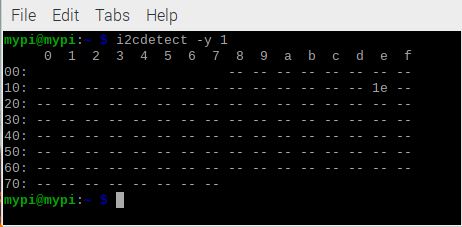
If everything is connected properly, you should see an address 1E appear in the list, which is the default address for the HMC5883L.
Python Code for Interfacing HMC5883L with Raspberry Pi
Here is a Python Code to interface HC5883L Magnetometer with Raspberry Pi 4. Copy the following code and paste it on your Thonny IDE. Then Save it with any name.
This simple Python script will read data from the HMC5883L.
|
1 2 3 4 5 6 7 8 9 10 11 12 13 14 15 16 17 18 19 20 21 22 23 24 25 26 27 28 29 30 31 32 33 34 35 36 37 38 39 40 41 42 43 44 45 46 47 48 49 50 51 52 53 54 55 56 57 58 59 60 61 62 63 64 65 66 67 68 |
import smbus import time import math # HMC5883L register addresses ADDRESS = 0x1E CONFIG_A = 0x00 CONFIG_B = 0x01 MODE = 0x02 X_MSB = 0x03 Z_MSB = 0x05 Y_MSB = 0x07 bus = smbus.SMBus(1) def setup(): bus.write_byte_data(ADDRESS, CONFIG_A, 0x70) # Set to 8 samples @ 15Hz bus.write_byte_data(ADDRESS, CONFIG_B, 0x20) # 1.3 gain LSb / Gauss 1090 (default) bus.write_byte_data(ADDRESS, MODE, 0x00) # Continuous measurement mode def read_raw_data(addr): # Read raw 16-bit value high = bus.read_byte_data(ADDRESS, addr) low = bus.read_byte_data(ADDRESS, addr+1) # Combine them to get a 16-bit value value = (high << 8) + low if value > 32768: # Adjust for 2's complement value = value - 65536 return value def compute_heading(x, y): # Calculate heading in radians heading_rad = math.atan2(y, x) # Adjust for declination angle (e.g. 0.22 for ~13 degrees) declination_angle = 0.22 heading_rad += declination_angle # Correct for when signs are reversed. if heading_rad < 0: heading_rad += 2 * math.pi # Check for wrap due to addition of declination. if heading_rad > 2 * math.pi: heading_rad -= 2 * math.pi # Convert radians to degrees for readability. heading_deg = heading_rad * (180.0 / math.pi) return heading_deg def main(): setup() while True: x = read_raw_data(X_MSB) y = read_raw_data(Y_MSB) z = read_raw_data(Z_MSB) heading = compute_heading(x, y) print(f"X: {x} uT, Y: {y} uT, Z: {z} uT, Heading: {heading:.2f}°") time.sleep(0.5) if __name__ == "__main__": main() |
This script initializes the HMC5883L in continuous measurement mode and then continuously reads and prints the X, Y, and Z magnetometer values. The data might need to be calibrated or adjusted depending on your application and surrounding magnetic fields.
To calculate the heading (or the orientation in degrees) using the magnetometer values, one usually makes use of the arctangent function. The heading can be determined from the X and Y magnetometer readings.
Testing & Results
You may run the above Python Script and the Thonny Shell will start showing the Magnetometer readings in micro-Tesla and Heading angles in degrees.

To observe the change in magnetic field values, bring any magnetic material or magnet near the sensor. You will observe drastic change in the magnetic field readings. The heading angle can be varied simly by rotating the sensor.

Remember, the computed heading will be relative to the Earth’s magnetic North and not the true North. This distinction is important if you are navigating based on the heading.
The difference between the magnetic North and the true North is known as the magnetic declination, and it varies depending on your geographic location. You might need to adjust the heading for magnetic declination based on where you’re located.


