

Overview:
In this tutorial we will interface Pyranometer Sensor with Arduino & measure Solar Radiation value.
A pyranometer is a type of sensor that measures the solar irradiance or the power of sunlight in watts per square meter (W/m²). The word “pyranometer” is derived from the Greek words “pyr” meaning “fire” and “ano” meaning “sky”. They are widely used in meteorology, climatology, solar energy studies, and agriculture to monitor and study the available solar radiation.
There are two types of Pyranometers, i.e. Thermopile Pyranometers and Silicon Pyranometers. In this project, we will use Thermopile Pyranometer from Renkeer. The sensor can measure solar irradiance between 0-2000W/m² with a resolution of 1W/m². The sensor works on RS485 protocol (4-20mA,0-5V, 0-10V). Hence we will use MAX485 Module to request the output data.

Using the RS485 Module, the Pyranometer Sensor data is processed by Arduino in readable format. Finally the Solar Radiation value is displayed on 16×2 LCD Display, interfaced to Arduino Board.
Bill of Materials
Following are the components that we need for reading Pyranometer Sensor data using an Arduino. The components can be purchased from given links.
| S.N. | Components | Quantity | Purchase Link |
|---|---|---|---|
| 1 | Arduino UNO Board | 1 | Amazon | AliExpress | SunFounder |
| 2 | Pyranometer Sensor | 1 | Renkeer |
| 3 | 16X2 I2C LCD Display | 1 | Amazon | AliExpress | SunFounder |
| 4 | MAX485 Module | 1 | Amazon | AliExpress | SunFounder |
| 5 | 12V Power Supply | 1 | Amazon | AliExpress | SunFounder |
| 6 | Jumper Wires | 10 | Amazon | AliExpress | SunFounder |
| 7 | Breadboard | 1 | Amazon | AliExpress | SunFounder |
Pyranometer Sensor
A pyranometer is an instrument designed to measure the solar irradiance, quantifying the sun’s energy in watts per square meter (W/m²). Solar radiation varies significantly among regions. Season and time of day are major considerations, but surrounding terrain elevation, man-made obstructions, and surrounding trees can also cause large variations in locations with a small area.
Renkeer Pyranometer Sensor

The Renkeer Pyranometer Sensor is currently one of the best sensor for measuring Solar Radiation. It measures the solar energy received from the entire hemisphere (180 degree field of view).
Utilizing the thermoelectric principle, this pyranometer accurately measures solar radiation within a spectral range of 0.3~3μm. The sensing element adopts a wire-wound electroplating thermopile, and the sensing surface is a black layer with high absorptivity.

Using the thermal effect of radiation, it absorbs solar radiation and converts it into thermoelectromotive force. It also has a temperature compensation function, which can accurately measure solar radiation. The double-layer glass cover above the sensing surface can not only reduce the influence of air convection on the device, but also block the radiation of the cover itself. And add a radiation shield to measure scattered radiation.
To prevent dew accumulation inside, it incorporates a desiccant-filled cartridge. Additionally, with an integrated bubble level and adjustable screws, the sensor can be precisely leveled without the need for a separate base. The product adopts the standard Modbus-RTU 485 communication protocol, which can directly read the current total solar radiation value.
Specifications of Renkeer Pyranometer Sensor
- Power supply range: 10V~30V DC
- Spectral range: 0.3~3μm
- Measuring range: 0-2000W/m²
- Resolution: 1W/m²
- Accuracy: ±3%
- Working environment: -40℃~60℃, 0~95%RH (non-condensing)
- Sensitivity: 7~14 μV·W-1·m2
- Internal resistance: about 300Ω
- Response time (99%): ≤30s
- Non-linear error: ≤±3%
- Corresponding error of directionality: ≤±30W/m²
- Temperature response error: ≤±8% (-40℃~+40℃)
- Yearly stability: ≤±3%
- Spectral selectivity: ≤±10%
- Cosine response error: ≤±5%
- Tilt response error: ≤±2%
- Output mode: RS485, 0-5V, 0-10V, 4-20ma
Working Principle Pyranometer Sensor
The working principle of Pyranometer Sensor is explained as follows:
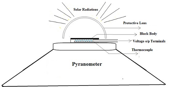
- Thermopile Sensing Element: At the heart of the pyranometer is its sensing element, which is typically a wire-wound, electroplated thermopile. A thermopile is a combination of multiple thermocouples (devices that generate a voltage based on the temperature difference between two junctions) connected in series or parallel. The design and arrangement of the thermopile help in amplifying the signal generated due to temperature differences.
- Absorptive Black Layer: The sensing surface of the pyranometer is coated with a black layer possessing high absorptivity. This ensures that the maximum amount of solar radiation is absorbed, which is crucial for achieving accurate measurements. As this black layer absorbs the incoming solar radiation, it heats up.
- Thermal Effect of Radiation: The fundamental concept driving the pyranometer’s operation is the thermal effect of radiation. When solar radiation is absorbed by the black layer, it generates a temperature difference across the thermopile. This temperature gradient leads the thermopile to produce a voltage difference.
- Output Measurement: The voltage produced by the thermopile is directly proportional to the absorbed solar radiation. Thus, this voltage becomes the pyranometer’s output and is used to determine the intensity of the incident solar irradiance.
- Temperature Compensation: A significant aspect of the pyranometer is its built-in temperature compensation mechanism. Changes in ambient temperature could potentially skew the readings of the instrument. However, the temperature compensation function ensures that the pyranometer provides accurate measurements of solar radiation, regardless of the surrounding temperature conditions.
Pyranometer Sensor installation
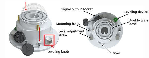
- Make sure to install the bracket, and the radiation sensor is parallel to the ground (leveling can be done through the leveling knob)
- Use screws to pass through the mounting holes on the sensor to fix the sensor on the mounting bracket
- After installation, remove the protective cover
- Please pay attention not to damage the glass cover during the installation process, so as not to affect the measurement accuracy
- The installation location should be an open place all around and without any obstructions.
Pyranometer Sensor Maintenance
- The glass cover should be kept smooth and clean, often wipe it with a soft cloth or fur
- There must be no water in the glass cover. If it encounters heavy rain, snow, ice, and other long-term weather, it is recommended to cover it
- It is recommended to check whether the desiccant in the dryer has become damp at regular intervals.
- The specific manifestation is that the orange turns into a dark color. If this happens, replace the desiccant in time, or remove the desiccant to dry and put it back into use
- The equipment has been used for more than two years, and the sensitivity must be re-calibrated by the manufacturer or measurement department
Applications of Pyranometer Sensor
- Meteorology: Pyranometers provide data for climate studies and weather prediction.
- Solar Energy: Engineers and researchers use pyranometers to assess and monitor the performance of photovoltaic (PV) systems.
- Agriculture: To study the effect of sunlight on crops, enabling farmers to optimize irrigation and planting strategies.
- Building and Architecture: For assessing solar irradiation for building design and energy modeling.
- Research: They’re commonly used in many scientific studies relating to the earth’s energy balance, climate change, and more.
Data Frame Format Definition & Communication Protocol
Data frame format definition
Using the Modbus-RTU communication protocol, the format is as follows:
- Initial structure ≥ 4 bytes of time
- Address code = 1 byte
- Function code = 1 byte
- Data area = N bytes
- Error check = 16-bit CRC code
- Time to end structure ≥ 4 bytes
Host query frame structure:
| Address Code | Function Code | Register Start Address | Register Length | Check code Low Bit | Check Code High Bit |
| 1 byte | 1 byte | 2 bytes | 2 bytes | 1 byte | 1 byte |
Slave response frame structure:
| Address Code | Function Code | Effective Number of Bytes | Data Area | Second Data Area | Nth Data Area | Check Code |
| 1 byte | 1 byte | 1 byte 1 byte | 2 bytes | 2 bytes | 2 bytes | 2 bytes |
Register Address
| Register address | content | Operation (hexadecimal) | Scope and definition |
| 0000H | Total solar radiation | 03 | actual value |
| 0052H | Deviation | 03/06 | Total solar radiation deviation value (0~2000) |
| 07D0H | Device address | 03/06 | 1~254 (factory default 1) |
| 07D1H | Device baud rate | 03/06 | 0 means 2400 1 is 4800 2 is 9600 |
Read the Current Solar Radiation Value
Inquiry frame:
| Address Code | Function Code | Initial Address | Data Length | Check code Low Bit | Check Code High Bit |
| 0x01 | 0x03 | 0x00 0x00 | 0x00 0x01 | 0x84 | 0x0A |
Response frame:
| Address Code | Function Code | Returns the number of valid bytes | Solar radiation value | Check code low bit | Check code high bit |
| 0x01 | 0x03 | 0x02 | 0x00 0x64 | 0x9B | 0xAF |
The Total solar radiation value from the response frame can be calculated as:
0064 (hexadecimal) =100=> total solar radiation value=100W/㎡
Interfacing Pyranometer Sensor with Arduino
Now lets interface the Pyranometer Sensor with Arduino & start measuring the Solar Radiation.
Hardware Connection
Here is the schematic for the project.

The Pyranometer sensor communicates with a Microcontroller using RS485 protocol. Hence we used MAX485 Module for this project. The MAX485 is a popular RS-485 transceiver chip commonly used for serial communication. When interfacing the MAX485 with an Arduino, you’ll typically be dealing with half-duplex communication, where data transmission and reception occur at different times.

Here is a connection mapping between MAX485 & Arduino.
- VCC (MAX485) -> 5V (Arduino)
- GND (MAX485) -> GND (Arduino)
- RO (MAX485) -> 2 (Digital Pin of Arduino)
- DI (MAX485) -> 3 (Digital Pin of Arduino)
- RE (MAX485) -> 8 (Digital Pin of Arduino)
- DE (MAX485) -> 7 (Digital Pin of Arduino)
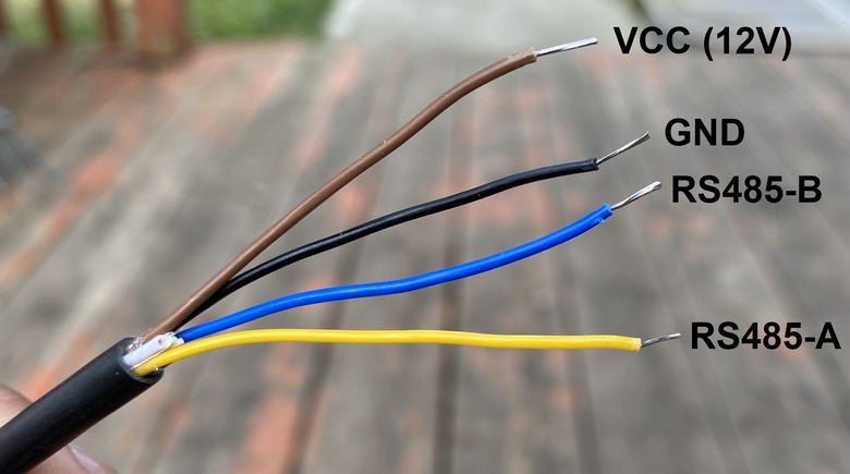
Here is a connection mapping between MAX485 & Pyanometer Sensor.
- VCC -> 12V (Pyranometer)
- GND -> GND (Pyranometer)
- A (MAX485) -> Pyranometer A Pin (Yellow Color)
- B (MAX485) -> Pyranometer B Pin (Blue Color)

You may use a breadboard for assembly and a jumper wires for connecting the sensor and RS485 Module with Arduino. The Pyranometer Sensor requires 12V for operation. You may use a 12V Battery or a 12V DC Power Supply.
Source Code/Program for Reading Solar Radiation Value
After assembling the sensor as per the circuit diagram above, lets move to the coding part of this project. According to the above table the inquiry frame for getting the Sensor reading hexadecimal is as follows:
|
1 |
0x01, 0x03, 0x00, 0x00, 0x00, 0x01, 0x84, 0x0A |
The sensor communicates at a baudrate of 4800. We have set the same parameter in the code to get the required reading.
Copy the following code and paste it on your Arduino IDE.
|
1 2 3 4 5 6 7 8 9 10 11 12 13 14 15 16 17 18 19 20 21 22 23 24 25 26 27 28 29 30 31 32 33 34 35 36 37 38 39 40 41 42 43 44 45 46 47 48 49 50 51 52 53 54 55 56 57 |
#include <SoftwareSerial.h> #define RE 8 #define DE 7 const byte pyranometer[] = {0x01, 0x03, 0x00, 0x00, 0x00, 0x01, 0x84, 0x0A}; byte values[8]; SoftwareSerial mod(2, 3); void setup() { Serial.begin(9600); mod.begin(4800); pinMode(RE, OUTPUT); pinMode(DE, OUTPUT); delay(1000); } void loop() { // Transmit the request to the sensor digitalWrite(DE, HIGH); digitalWrite(RE, HIGH); delay(10); mod.write(pyranometer, sizeof(pyranometer)); digitalWrite(DE, LOW); digitalWrite(RE, LOW); delay(10); // Give some time for the sensor to respond // Wait until we have the expected number of bytes or timeout unsigned long startTime = millis(); while (mod.available() < 7 && millis() - startTime < 1000) { delay(1); } // Read the response byte index = 0; while (mod.available() && index < 8) { values[index] = mod.read(); Serial.print(values[index], HEX); Serial.print(" "); index++; } Serial.println(); // Parse the Solar Radiation value int Solar_Radiation = int(values[3] << 8 | values[4]); Serial.print("Solar Radiation: "); Serial.print(Solar_Radiation); Serial.println(" W/m^2"); delay(3000); } |
Code Explanation
|
1 |
#include <SoftwareSerial.h> |
In the beginning, the SoftwareSerial library is included. This allows the Arduino to create a secondary serial connection using any digital pins, which is necessary because the RS485 module requires a different set of pins for communication than the standard RX and TX pins.
|
1 2 |
#define RE 8 #define DE 7 |
Then, the pins RE and DE for the RS485 module are defined. These pins help in toggling between transmission and reception modes.
|
1 |
const byte pyranometer[] = {0x01, 0x03, 0x00, 0x00, 0x00, 0x01, 0x84, 0x0A}; |
The constant byte array pyranometer is a pre-defined command set. When this command is sent to the solar radiation sensor, it prompts the sensor to send back the solar radiation data.
|
1 2 |
byte values[8]; SoftwareSerial mod(2, 3); |
For storing the data received from the sensor, an 8-byte array named values is declared. Furthermore, a software serial connection named mod is initiated on digital pins 2 (RX) and 3 (TX).
|
1 2 3 |
void setup() { ... } |
In the setup() function, standard procedures are performed. The primary serial connection (used for debugging and logging to the Serial Monitor) is started with a baud rate of 9600. The software serial mod begins at 4800, which is presumably the communication rate with the sensor. Pins RE and DE are set as OUTPUT, preparing them to toggle the RS485’s mode. Finally, a delay ensures everything stabilizes before the main loop starts.
|
1 2 |
digitalWrite(DE, HIGH); digitalWrite(RE, HIGH); |
Within the loop(), the process of querying the sensor and reading its response is performed repeatedly. First, by setting both RE and DE pins HIGH, the RS485 module is prepped for transmission.
|
1 |
mod.write(pyranometer, sizeof(pyranometer)); |
After a brief pause to ensure stability, the command set stored in the pyranometer array is sent to the sensor:
|
1 2 |
digitalWrite(DE, LOW); digitalWrite(RE, LOW); |
Once the command is sent, the module is quickly switched back to “receive” mode to listen for the sensor’s response.
|
1 |
int Solar_Radiation = int(values[3] << 8 | values[4]); |
The code then reads the incoming bytes from the sensor and stores them in the values array. This process happens byte by byte, and each byte is simultaneously printed on the Serial Monitor in HEX format.
From the data gathered in the values array, the solar radiation value is extracted. The data from the sensor is spread across two bytes, with one representing the higher byte and the other the lower byte. The code merges these bytes into a single integer, which depicts the solar radiation.
|
1 2 3 |
Serial.print("Solar Radiation: "); Serial.print(Solar_Radiation); Serial.println(" W/m^2"); |
Finally, the extracted solar radiation value is printed on the Serial Monitor, and the loop waits for 3 seconds before repeating the process.
Testing & Results
To upload the code to the Arduino UNO Board, select Arduino UNO from Board list. Then Select the COM Port. Finally click on the upload button to upload the code.
Once code is uploaded, open the Serial Monitor and you will see following readings.
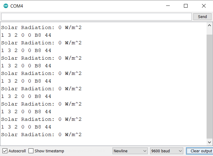
The reading will appear zero as, you need to remove the sensor cap from the Dome Shaped glass. Once the Glass is removed, you will notice the change in reading. This will basically show the reading of Solar Irradiance.
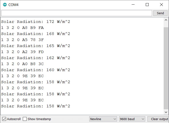
Expose the Sensor in the bright sunlight. The reading will rise quickly.
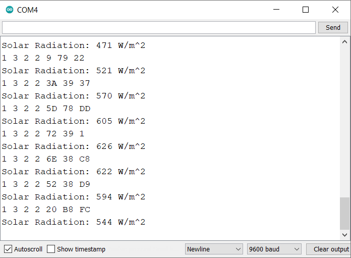
The Solar radiation measured value depends upon the quantity of light falling on the dome shaped glass. The sunlight intensity varies from morning to evening and also depends upon the clouds in the sky. The earthe geographical region is also responsible for varaying Solar irradiance value.
Interfacing Pyranometer Sensor with Arduino & LCD Display
Now lets interface the Pyranometer Sensor with Arduino and 16×2 LCD Display and observe the Solar Radiation Value on LCD.
Hardware Connection
Here is the connection diagram for adding an extra LCD connection.

The sensor and RS485 connections remains same as above. Only the connection for LCD changes as follows:
- VCC (LCD) -> 5V (Arduino)
- GND (LCD) -> GND (Arduino)
- SDA (LCD) -> A4 (Arduino)
- SCL (LCD) -> A5 (Arduino)

Source Code/Program Displaying Solar Radiation Value on LCD
Here is the final code for displaying Solar Radiation value on LCD Display using the Arduino Board and Pyranometer Sensor.
The code requires I2C LCD Library for compilation. Therefore download the library and add it to the Arduino library folder.
Now copy the following code and paste it to the Arduino IDE.
|
1 2 3 4 5 6 7 8 9 10 11 12 13 14 15 16 17 18 19 20 21 22 23 24 25 26 27 28 29 30 31 32 33 34 35 36 37 38 39 40 41 42 43 44 45 46 47 48 49 50 51 52 53 54 55 56 57 58 59 60 61 62 63 64 65 66 67 68 69 70 71 72 73 |
#include <SoftwareSerial.h> #include <LiquidCrystal_I2C.h> LiquidCrystal_I2C lcd(0x27, 16, 2); // set the LCD address to 0x27 for a 16 chars and 2 line display #define RE 8 #define DE 7 const byte pyranometer[] = {0x01, 0x03, 0x00, 0x00, 0x00, 0x01, 0x84, 0x0A}; byte values[8]; SoftwareSerial mod(2, 3); void setup() { Serial.begin(9600); lcd.init(); lcd.backlight(); mod.begin(4800); pinMode(RE, OUTPUT); pinMode(DE, OUTPUT); lcd.setCursor(0, 0); lcd.print("Solar Radiation"); lcd.setCursor(2, 1); lcd.print("Measurement"); delay(3000); } void loop() { // Transmit the request to the sensor digitalWrite(DE, HIGH); digitalWrite(RE, HIGH); delay(10); mod.write(pyranometer, sizeof(pyranometer)); digitalWrite(DE, LOW); digitalWrite(RE, LOW); delay(10); // Give some time for the sensor to respond // Wait until we have the expected number of bytes or timeout unsigned long startTime = millis(); while (mod.available() < 7 && millis() - startTime < 1000) { delay(1); } // Read the response byte index = 0; while (mod.available() && index < 8) { values[index] = mod.read(); Serial.print(values[index], HEX); Serial.print(" "); index++; } Serial.println(); // Parse the Solar Radiation value int Solar_Radiation = int(values[3] << 8 | values[4]); Serial.print("Solar Radiation: "); Serial.print(Solar_Radiation); Serial.println(" W/m^2"); lcd.clear(); lcd.setCursor(0, 0); lcd.print("Solar Radiation"); lcd.setCursor(0, 1); lcd.print(Solar_Radiation); lcd.print(" W/m^2"); delay(2000); } |
Testing & Results
Upload the code to the Arduino UNO Board. The Arduino code is now ready to give the Solar Radiation reading on LCD Display.

The LCD will display the Solar Radiation Sensor value as zero. This is because you need to remove cap from the Dome Shape.

Take the sensor outdoor during the day time for reading. Under the shadow, the Solar Irradiance reading was observed as 82 W/m^2.
Expose the Sensor under the sunlight.

In this case, the LCD showed the reading of 689 W/m^2. In some case reading even crossed 1000 W/m^2.
During the testing phase, the sky was Cloudy and hence reading changed randomly.

The testing can be conducted entire year to observe seasonal reading changes. We tested the Sensor from Canada (North America Region). This part of the region recieves very less sunlight compared to Africa or Indian Subcontinent. Therefore reading may be high in these regions.
Video Tutorial & Guide

Conclusion
Upon interfacing the Pyranometer Sensor with an Arduino setup, we successfully gauged solar radiation values under varying conditions. The data, reflected on the 16×2 LCD Display, revealed 82 W/m^2 in shaded areas and a substantial increase to 689 W/m^2 or 1000 W/m^2 in direct sunlight. Given the evident fluctuations during a cloudy day, the sensor’s keen sensitivity to environmental nuances was confirmed. Moreover, our observations from Canada indicated a distinct regional variation in solar irradiance, suggesting that sunnier locales like Africa or the Indian Subcontinent might exhibit elevated readings.
The applications of this sensor span beyond mere data collection; its potential in meteorological studies, solar power assessment, agriculture, and even architectural planning highlights its versatility. In light of our findings, any comprehensive evaluation of solar radiation should consider both geographical and seasonal nuances. Expanding the scope of testing across diverse global regions could enrich our understanding further.

")


1 Comment
Hello,
I am trying to make it work with Arduino Mega. However I haven’t be able. I got always zero and timeout response error. Any recommendation?