

Overview
The project involves creating an “IoT Solar Panel Monitoring System” using ESP8266 and MQTT. This innovative system is designed to accurately monitor and report various crucial parameters of a solar panel setup. Key features include the ability to measure solar panel voltage, current, power output, energy consumption in kilowatt-hours (KWh), and temperature.
The core of this system is the ESP8266, a powerful and versatile microcontroller with Wi-Fi capability, which facilitates seamless connectivity and data transmission. The integration with MQTT Ubidots enables the efficient and reliable upload of collected data to the cloud. Ubidots, a user-friendly IoT platform, provides a convenient interface for data visualization and analysis.
Earlier we build a basic version of ESP32 Solar Power Monitoring. But this is the advanced system that measures various solar parameters and in more advance way. We have designed a dedicated custom PCB for this project where all the SMD and through-hole components can be soldered. The PCB is well tested and can be used for your IoT Solar Panel Monitoring System applications.
Bill of Materials
For the IoT Solar Panel Monitoring System, we need the following components. The components are mostly SMD type with 0805 packages for resistor, capacitor, and LED.
| S.N. | Components | Designator | Footprint | Quantity | Part Number |
|---|---|---|---|---|---|
| 1 | ESP8266-12E | U1 | WIFIM-SMD_ESP-12E | 1 | ESP-12E |
| 2 | LM7805 5V Regulator | U2 | TO-220-3 | 1 | LM7805 |
| 3 | DS18B20 Temperature Sensor | U6 | TO-92-3 | 1 | DS18B20 |
| 4 | INA226 | U3 | 1x8 2.54MM | 1 | INA226 |
| 5 | HT7333 LDO | U4 | SOT-89-3 | 1 | HT7333-7 |
| 6 | Resistor 220E | R9 | R0805 | 1 | |
| 7 | Resistor 330 | R6 | R0805 | 1 | |
| 8 | Resistor 12K | R1,R2,R3,R4,R5 | R0805 | 5 | |
| 9 | Resistor 22K | R7,R8 | R0805 | 2 | |
| 10 | Resistor 4.7K | R10 | R805 | 1 | |
| 11 | Capacitor 0.1uF | C1 | C0805 | 1 | |
| 12 | Capacitor 470pF | C2 | C0805 | 1 | |
| 13 | Capacitor 10uF | C3,C4 | C0805 | 2 | |
| 14 | Capacitor 47uF, 10V | C6 | CAP-TH_BD6.3-P2.50-D0.5-FD | 1 | |
| 15 | Capacitor 220uF, 50V | C5 | CAP-TH_BD8.0-P3.50-D0.6-FD | 1 | |
| 16 | LED Red | LED1 | LED0805 | 1 | |
| 17 | Transistor BC847 | Q1,Q2 | SOT-23-3 | 2 | BC847A |
| 18 | Push Button | FLS,RST | SW-SMD_L4.0-W3.0-LS4.8 | 2 | TS-1071AS-A1B3-D4 |
| 19 | Slide Switch | SW1 | SW-TH_MK-12D18-G040 | 1 | MK-12D18-G020 |
| 20 | Header Pins 1x6 | PROG | Male Header 1x6 2.54mm | 1 | |
| 21 | Header Pins (1x4) | U5 | Female Header 1x4 2.54mm | 1 | |
| 22 | Terminal Block (1x2) | LOAD, BAT. | TERMINAL_BLOCK_2P_5 | 2 |
Designing of IoT Solar Panel Monitoring System Hardware
Let us take a look at the circuit for IoT Solar Panel Monitoring System using ESP8266. We could have used INA219 Current Sensor for this project, but INA226 has voltage limitations of 26V and the maximum current it can measure is ±3.2A.
We need a sensor that can measure more voltage and current. The INA226 is the best alternative considering the cost and accuracy. We can measure the voltage up to 36V and the current up to 30A. The current setting is based on the shunt resistance that needs to be selected based on the above table.
Since the device is IoT Based, we used ESP8266 raw chip for this purpose. The entire device is powered using an external power source. Here is the complete schematic for the project.
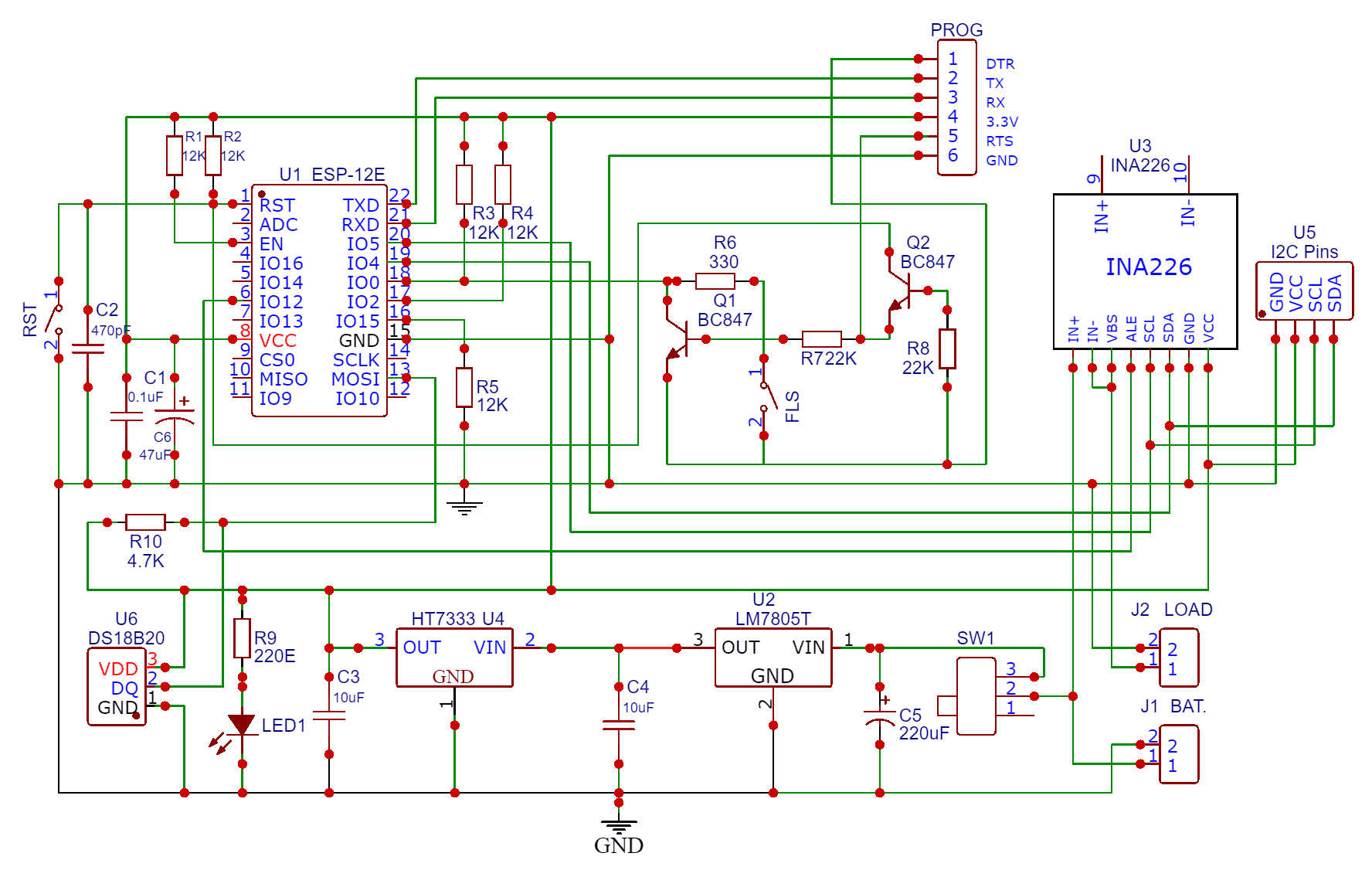
The external DC source Solar Panel is used to power the circuit. The input voltage should be between 7V to 36V only. The Switch SW1 is used to power on/off the circuit. The Input voltage is fed to the 7805 Voltage regulator IC. Use a proper heat sink for 7805 if the supply voltage is greater than 12V. The capacitor C5 (220uF, 50V) filters input voltages and makes stability. The LM7805 IC outputs 5V DC which is fed to LDO HT7333. The HT7333 limits the voltage to 3.3V. The entire circuit operates at 3.3V. The LED1 indicates whether the circuit is powered on or off.
Moving to the ESP8266 chip part, we have used our ESP8266 Automatic Programmer Circuit. There is no need to press the reset or boot button while uploading the code. You can connect USB-to-TTL Converter Module to PROG Pins & program the circuit. The programming process is automatic and handled by two switches (FLS and RST), two BC547 transistors (Q1 and Q2), and a few other components.

The RTS signal resets the ESP8266, while the DTR signal puts it in flash mode, with Q1 and Q2 preventing the chip’s reset when both signals are low. Upon detecting an upload command, the ESP module auto-switches to flash mode for seamless sketch uploading. In the absence of an upload command, ESP-12E/F starts in normal mode.
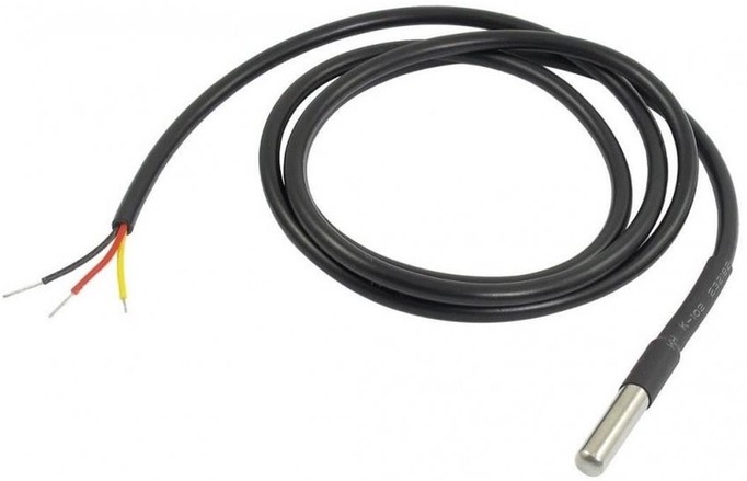
To measure the temperature of the Solar Panel, we are using DS18B20 Waterproof Temperature Sensor. The DS18B20 is a waterproof digital temperature sensor, widely used in various temperature monitoring applications due to its unique combination of features. Its signal pin is connected to GPIO13 of ESP8266.
For the INA226 Current sensor, the SDA and SCL pins are connected to the SDA & SCL pins of the ESP8266 Chip. The Vin+ pin should be connected to a power source and the Vin- to the load as shown in the design schematic. The INA226 Sensor has VBus Pin, which is used to measure the Load Voltage. Therefore we need to connect the VBus pin to Vin- pin.
The U5 part in the circuit is the I2C and Power pins. You can directly connect a 0.96″ I2C OLED Display here. The 0.96″ I2C LCD Display shows the value of Solar Voltage, Current, Power, Energy Consumption and Temperature.
Project PCB Design, Gerber File & PCB Ordering Online
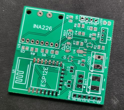
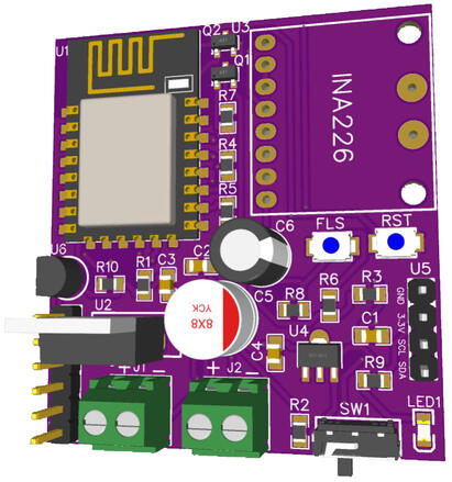
We have designed the PCB using the Altium Designer Software. It took quite a lot of time fixing all the issues in the PCB but still we managed to design a complete working custom PCB. The PCB design looks like this.
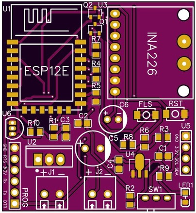
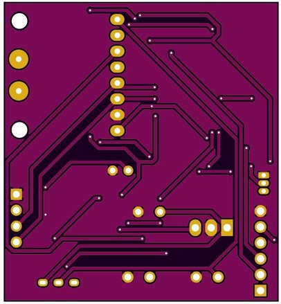
The PCB has SMD components with resistors, capacitors, and LED with an SMD package of 0805. The transistors, and push buttons are also in the SMD package. The front side of the PCB has all the components to be mounted.
The Gerber File for the PCB is given below. You can simply download the Gerber File and order the PCB from PCBGOGO at 1$ only.
You can use this Gerber file to order high-quality PCB for this project. To do that visit the PCBGOGO official website by clicking here: https://www.pcbgogo.com/.

You can now upload the Gerber File by choosing the Quote Now option. From these options, you can choose the Material Type, Dimensions, Quantity, Thickness, Solder Mask Color and other required parameters.

After filling all details, select your country and shipping method. Finally you can place the order.
PCB & Hardware Assembly
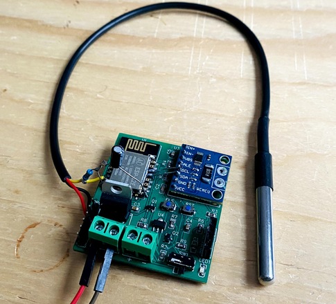
After ordering the PCB, it took almost 5 days and I got my PCB.

The PCB quality from PCBGOGO is superb with very high quality. That is why most people trust PCBGOGO for PCB/PCBA Services.
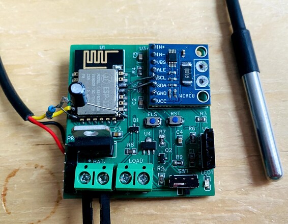
On the front side, first solder all the SMD components like resistors, capacitors, transistors, LED & push buttons. Be careful about the SMD LED polarity, place it in the proper direction. After soldering all these, you can solder the ESP8266 raw chip. The final stage would be soldering all the through-hole components like Switch, terminal block, male-female headers, and INA226 Sensor
After soldering all the components, the IoT Solar Panel Monitoring using ESP8266 is ready for the test. You can upload a blink sketch by connecting a USB-to-TTL Converter Module.
Note: There were some voltage fluctuation issues in the designed PCB, so I have updated the design by adding some large capacitors. Also, some connection issues have been fixed. The Gerber file above is updated and the PCB would look something like this.
Setting Up Ubidots Account & Dashboard
To monitor the Solar Panel parameters like Solar Voltage, Current, Power, Energy Consumption, Temperature we need some Web dashboard. We will be using Ubidots for this application.

Ubidots is a cloud-based Internet of Things (IoT) platform that provides tools and services for capturing, analyzing, and visualizing data from sensors and devices.
Go to the Ubidots website (ubidots.com) and click on the “Sign Up” button. Ubidots offers different types of accounts, such as Ubidots STEM for students and educators, and Ubidots Industrial for more advanced commercial uses. Choose the one that best suits your needs.
Click on Profile and and then click on “API Credentials“.
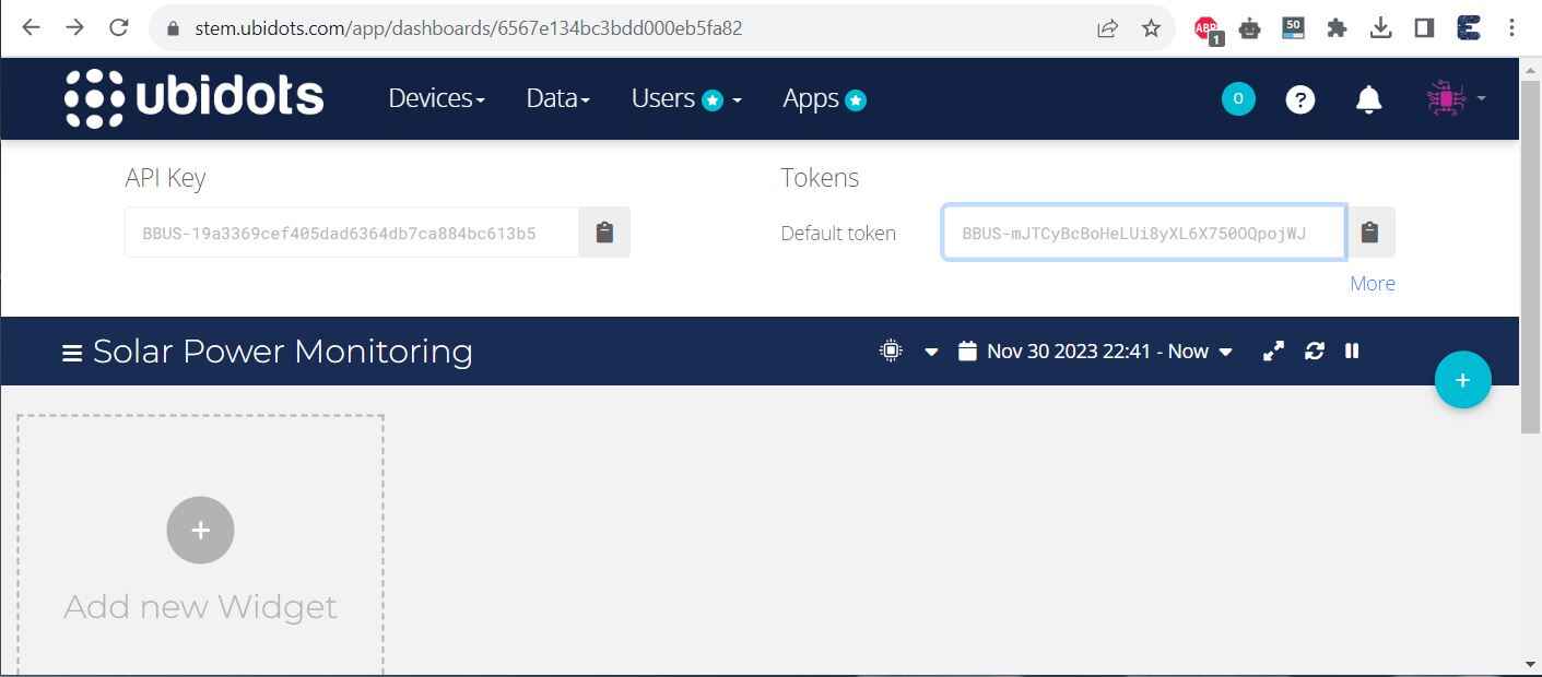
Copy the API and Tokens. This will be used in the code part.
Now the setup part is completed. The rest of the setup is needed only after uploading of code.
Source Code/Program
After the hardware and Ubidots Setup is done, we need to move to the coding part. The IoT Solar Panel Monitoring System with ESP8266 requires ESP8266 firmware for reading INA226 & DS18B20 Data and sending it to Ubidots Dashboard over MQTT.
Before moving to the coding part add the following libraries to the Arduino IDE, using the library manager.
- INA226 Library
- OneWire Library
- Dallas Temperature Library
- PubSubClient Library
- Adafruit GFX Library
- Adafruit SSD1306 Library
From the following lines of the code change the WiFi SSID, Password, Ubidots Authentication Token, and MQTT_CLIENT_NAME.
|
1 2 3 4 |
#define WIFISSID "**********" // Put your Wifi SSID here #define PASSWORD "**********" // Put your wifi password here #define TOKEN "**********" // Put your Ubidots' TOKEN #define MQTT_CLIENT_NAME "Solar_Monitoring" // MQTT client Name, please enter your own 8-12 alphanumeric character ASCII string; |
Here is the complete code for IoT Solar Panel Monitoring System with ESP8266 & MQTT. Copy the code and paste it on your Arduino IDE.
|
1 2 3 4 5 6 7 8 9 10 11 12 13 14 15 16 17 18 19 20 21 22 23 24 25 26 27 28 29 30 31 32 33 34 35 36 37 38 39 40 41 42 43 44 45 46 47 48 49 50 51 52 53 54 55 56 57 58 59 60 61 62 63 64 65 66 67 68 69 70 71 72 73 74 75 76 77 78 79 80 81 82 83 84 85 86 87 88 89 90 91 92 93 94 95 96 97 98 99 100 101 102 103 104 105 106 107 108 109 110 111 112 113 114 115 116 117 118 119 120 121 122 123 124 125 126 127 128 129 130 131 132 133 134 135 136 137 138 139 140 141 142 143 144 145 146 147 148 149 150 151 152 153 154 155 156 157 158 159 160 161 162 163 164 165 166 167 168 169 170 171 172 173 174 175 176 177 178 179 180 181 182 183 184 185 186 187 188 189 190 191 192 193 194 195 196 197 198 199 200 201 202 203 204 205 206 207 208 209 210 211 212 213 214 215 216 217 218 219 220 221 222 223 224 225 226 227 228 229 230 231 232 233 234 235 236 237 238 239 240 241 242 243 244 245 246 247 248 249 250 251 252 253 254 255 256 |
#include <Wire.h> #include <INA226_WE.h> #include <OneWire.h> #include <DallasTemperature.h> #include <ESP8266WiFi.h> #include <PubSubClient.h> #include <Adafruit_GFX.h> #include <Adafruit_SSD1306.h> #define WIFISSID "***********" // Put your WifiSSID here #define PASSWORD "***********" // Put your wifi password here #define TOKEN "***********" // Put your Ubidots' TOKEN #define MQTT_CLIENT_NAME "Solar_Monitoring" // MQTT client Name, please enter your own 8-12 alphanumeric character ASCII string; #define I2C_ADDRESS 0x40 INA226_WE ina226 = INA226_WE(I2C_ADDRESS); #define SCREEN_WIDTH 128 #define SCREEN_HEIGHT 64 #define OLED_RESET -1 Adafruit_SSD1306 display(SCREEN_WIDTH, SCREEN_HEIGHT, &Wire, OLED_RESET); #define ONE_WIRE_BUS 13 // Setup a oneWire instance to communicate with any OneWire devices OneWire oneWire(ONE_WIRE_BUS); // Pass our oneWire reference to Dallas Temperature sensor DallasTemperature sensors(&oneWire); float Source_Voltage = 0.0; float Current = 0.0; float Power = 0.0; float kWh = 0; float Temperature = 0; /**************************************** Define Constants ****************************************/ #define VARIABLE_LABEL1 "Solar Voltage" // Assing the variable label #define VARIABLE_LABEL2 "Current" #define VARIABLE_LABEL3 "Power" #define VARIABLE_LABEL4 "KWh" #define VARIABLE_LABEL5 "Temperature" #define DEVICE_LABEL "ESP8266" char mqttBroker[] = "industrial.api.ubidots.com"; char payload[1000]; char topic1[150]; char topic2[150]; char topic3[150]; char topic4[150]; char topic5[150]; // Space to store values to send char str_Solar_Voltage[10]; char str_Current[10]; char str_Power[10]; char str_KWh[10]; char str_Temperature[10]; WiFiClient ubidots; PubSubClient client(ubidots); unsigned long lastmillis = millis(); void callback(char* topic, byte* payload, unsigned int length) { char p[length + 1]; memcpy(p, payload, length); p[length] = NULL; String message(p); Serial.write(payload, length); Serial.println(topic); } void reconnect() { // Loop until we're reconnected while (!client.connected()) { Serial.println("Attempting MQTT connection..."); // Attemp to connect if (client.connect(MQTT_CLIENT_NAME, TOKEN, "")) { Serial.println("Connected"); } else { Serial.print("Failed, rc="); Serial.print(client.state()); Serial.println(" try again in 2 seconds"); // Wait 2 seconds before retrying delay(2000); } } } void setup() { Serial.begin(115200); sensors.begin(); Wire.begin(); ina226.init(); /* Set Number of measurements for shunt and bus voltage which shall be averaged Mode * * Number of samples AVERAGE_1 1 (default) AVERAGE_4 4 AVERAGE_16 16 AVERAGE_64 64 AVERAGE_128 128 AVERAGE_256 256 AVERAGE_512 512 AVERAGE_1024 1024*/ //ina226.setAverage(AVERAGE_16); // choose mode and uncomment for change of default /* Set conversion time in microseconds One set of shunt and bus voltage conversion will take: number of samples to be averaged x conversion time x 2 Mode * * conversion time CONV_TIME_140 140 µs CONV_TIME_204 204 µs CONV_TIME_332 332 µs CONV_TIME_588 588 µs CONV_TIME_1100 1.1 ms (default) CONV_TIME_2116 2.116 ms CONV_TIME_4156 4.156 ms CONV_TIME_8244 8.244 ms */ //ina226.setConversionTime(CONV_TIME_1100); //choose conversion time and uncomment for change of default /* Set measure mode POWER_DOWN - INA226 switched off TRIGGERED - measurement on demand CONTINUOUS - continuous measurements (default)*/ //ina226.setMeasureMode(CONTINUOUS); // choose mode and uncomment for change of default /* Set Resistor and Current Range if resistor is 5.0 mOhm, current range is up to 10.0 A default is 100 mOhm and about 1.3 A*/ ina226.setResistorRange(0.1, 1.3); // choose resistor 0.1 Ohm and gain range up to 1.3A /* If the current values delivered by the INA226 differ by a constant factor from values obtained with calibrated equipment you can define a correction factor. Correction factor = current delivered from calibrated equipment / current delivered by INA226*/ ina226.setCorrectionFactor(0.93); Serial.println("INA226 Current Sensor Example Sketch - Continuous"); ina226.waitUntilConversionCompleted(); //if you comment this line the first data might be zero display.begin(SSD1306_SWITCHCAPVCC, 0x3C); delay(500); display.clearDisplay(); display.setTextColor(WHITE); WiFi.begin(WIFISSID, PASSWORD); Serial.println(); Serial.print("Waiting for WiFi Connection .............."); while (WiFi.status() != WL_CONNECTED) { Serial.print("."); delay(500); } Serial.println(""); Serial.println("WiFi Connected"); Serial.println("IP address: "); Serial.println(WiFi.localIP()); client.setServer(mqttBroker, 1883); client.setCallback(callback); } void loop() { if (!client.connected()) { reconnect(); } sensors.requestTemperatures(); Temperature = sensors.getTempCByIndex(0); ina226.readAndClearFlags(); Source_Voltage = ina226.getBusVoltage_V(); Current = ina226.getCurrent_mA(); Power = ina226.getBusPower(); // to convert to Wh, use the formula: Wh = Wh + Power * (millis() - lastmillis) / 3600000.0; //Here we are converting to kWh kWh = kWh + Power * (millis() - lastmillis) / 3600000000.0; display.clearDisplay(); display.setTextSize(1); display.setCursor(0, 0); display.print("Voltage: "); display.print(Source_Voltage); display.print("V"); display.setCursor(0, 10); display.print("Current: "); display.print(Current); display.print("mA"); display.setCursor(0, 20); display.print("Power: "); display.print(Power); display.print("mW"); display.setCursor(0, 30); display.print("kWh: "); display.print(kWh); display.print("kWh"); display.setCursor(0, 40); display.print("Temperature: "); display.print(Temperature); display.print("*C"); display.display(); lastmillis = millis(); // Update lastmillis for the next loop // Convert float values to strings dtostrf(Source_Voltage, 4, 2, str_Solar_Voltage); dtostrf(Current, 4, 2, str_Current); dtostrf(Power, 4, 2, str_Power); dtostrf(kWh, 4, 2, str_KWh); dtostrf(Temperature, 4, 2, str_Temperature); // Construct a single payload with all data sprintf(payload, "{\"%s\":{\"value\":%s}, \"%s\":{\"value\":%s}, \"%s\":{\"value\":%s}, \"%s\":{\"value\":%s}, \"%s\":{\"value\":%s}}", VARIABLE_LABEL1, str_Solar_Voltage, VARIABLE_LABEL2, str_Current, VARIABLE_LABEL3, str_Power, VARIABLE_LABEL4, str_KWh, VARIABLE_LABEL5, str_Temperature); // Publish the payload to Ubidots sprintf(topic1, "/v1.6/devices/%s", DEVICE_LABEL); Serial.println("Publishing data to Ubidots Cloud"); client.publish(topic1, payload); Serial.println(payload); // For debugging purposes client.loop(); delay(5000); // Adjust the delay as per your requirement } |
Testing the Hardware
To test whether you are able to upload the code to the ESP8266 Chip or not, connect a USB-to-TTL Converter Module (FTDI) to the Board using the pins mentioned in the PCB. Make sure to connect the RTS pin from the side of the USB-to-TTL Module as well.
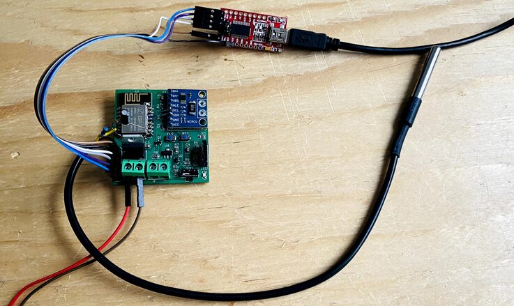
Connect the FTDI Board to your computer. From the Board list Select “Generic ESP8266” Board and also select the COM port.

Now hit the upload button to upload the code. After successful code uploading, open the Serial Monitor.
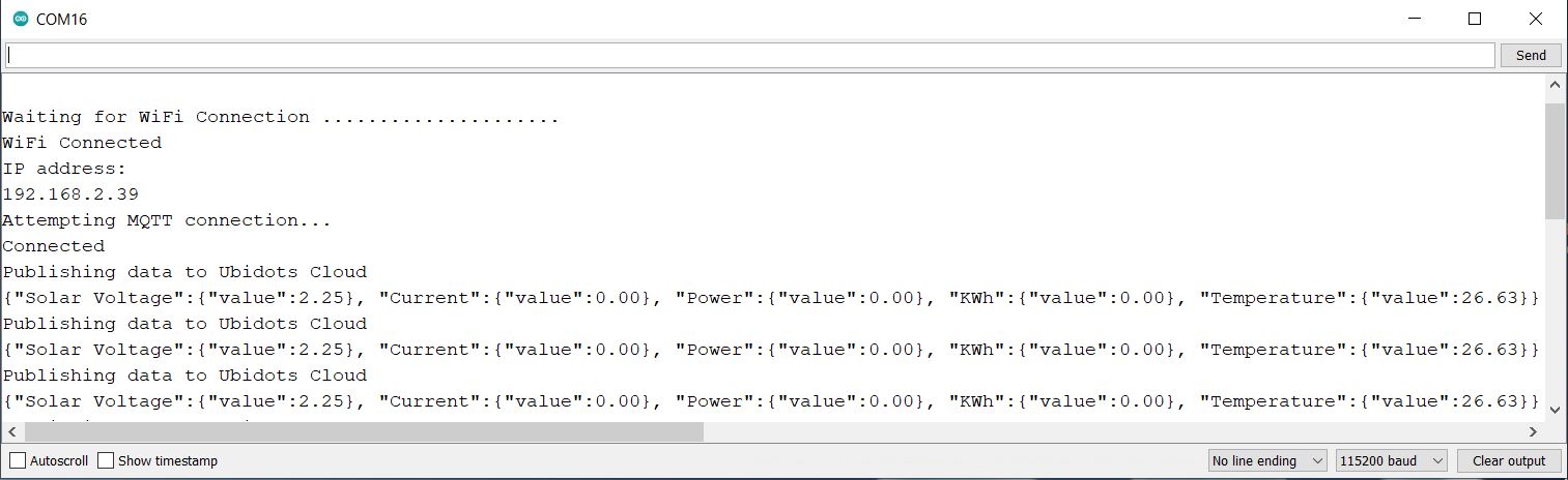
The Serial Monitor will show all the values zero except the voltage and temperature. This is because currently no Solar Panel is connected to the Board.
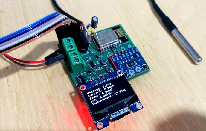
The OLED Display will also show the value of Solar Voltage, Current, Power, Energy Consumption & Temperature.
Monitoring Solar Panel & Data Visualization on Ubidots
After the above testing is completed, we can do the testing with the Solar Panel. The input voltage accepted by the hardware is between 7-36V, therefore connect any Solar Panel within the voltage range.

For our testing, we are using a 20V, 30W Solar Panel. The Solar voltage depends upon the light intensity. Therefore check the voltage in outdoor conditions.
Connect the Solar Panel to the input terminal of the board.

Once the Solar Panel is connected, the device gets powered ON. Soon the ESP8266 will connect to the WiFi network using the WiFi credentials. Then the data is read by the sensor and using the ESP8266, the sensor’s values get uploaded to the Ubidots Dashboard.
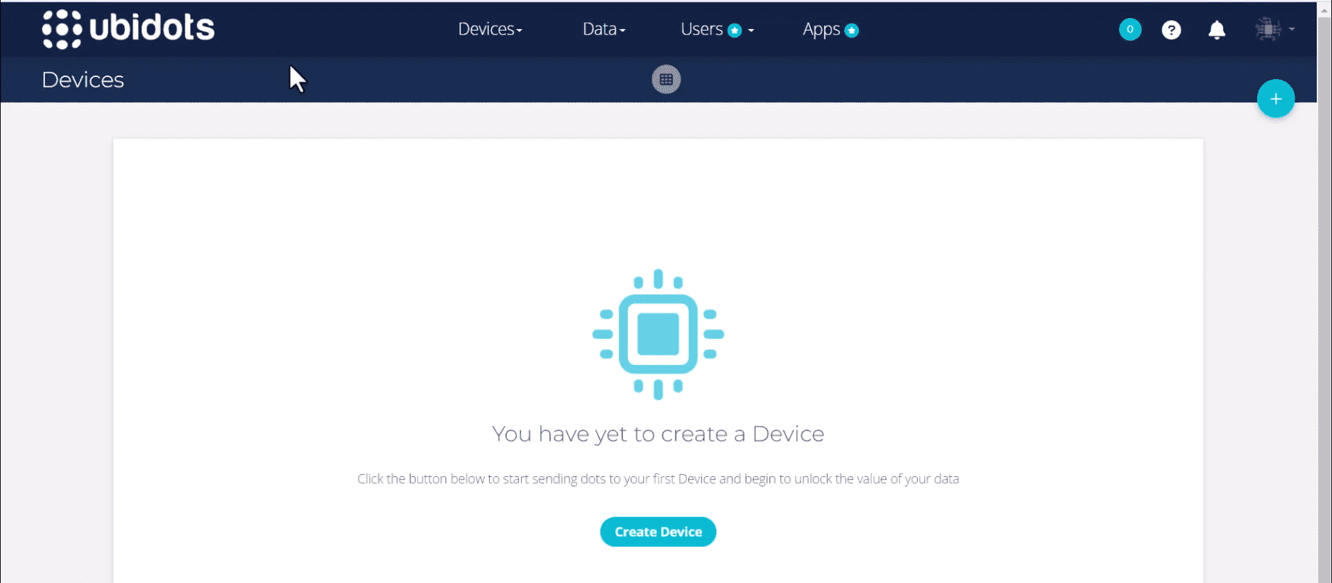
Intially when you check the device section of Ubidots Dashboard, no devices appear.
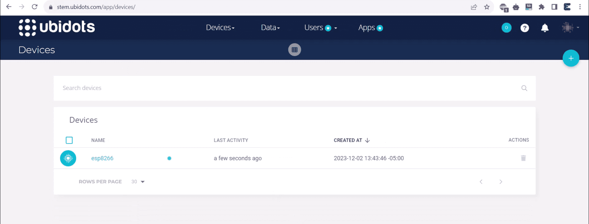
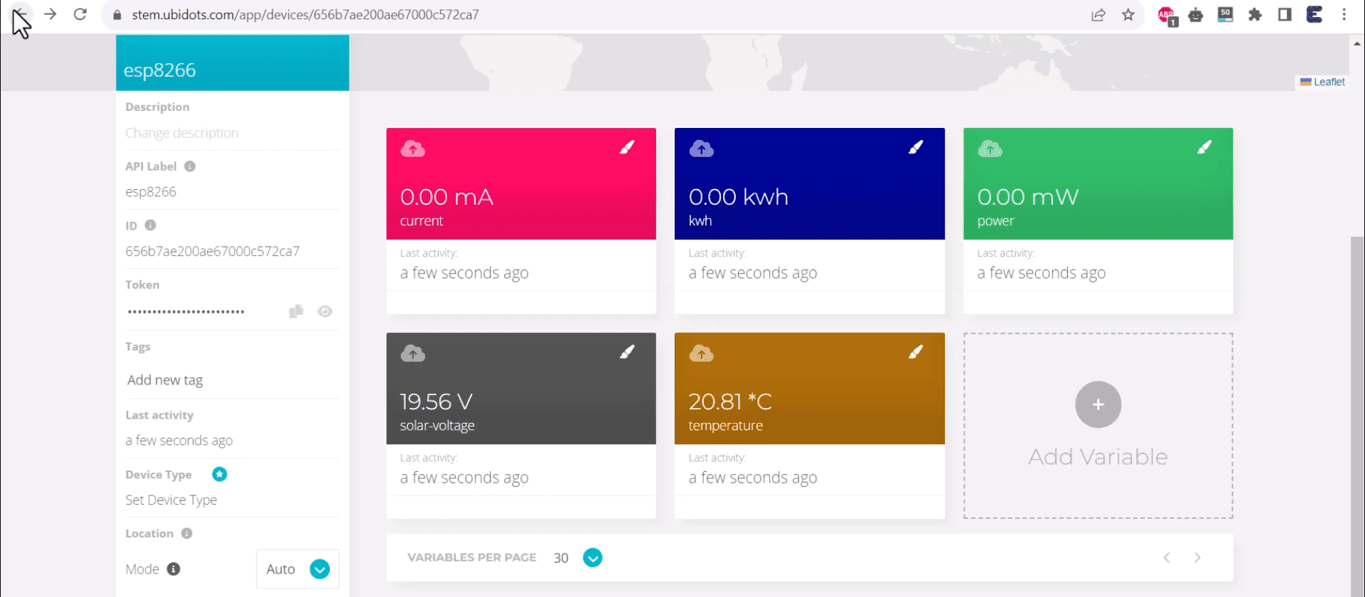
You need to refresh the page. Once the page is refreshed, the device named ESP8266 will appear.
Click on the device. You will see the variables logged in as Voltage, Current, Power, kWh, and Temperature.
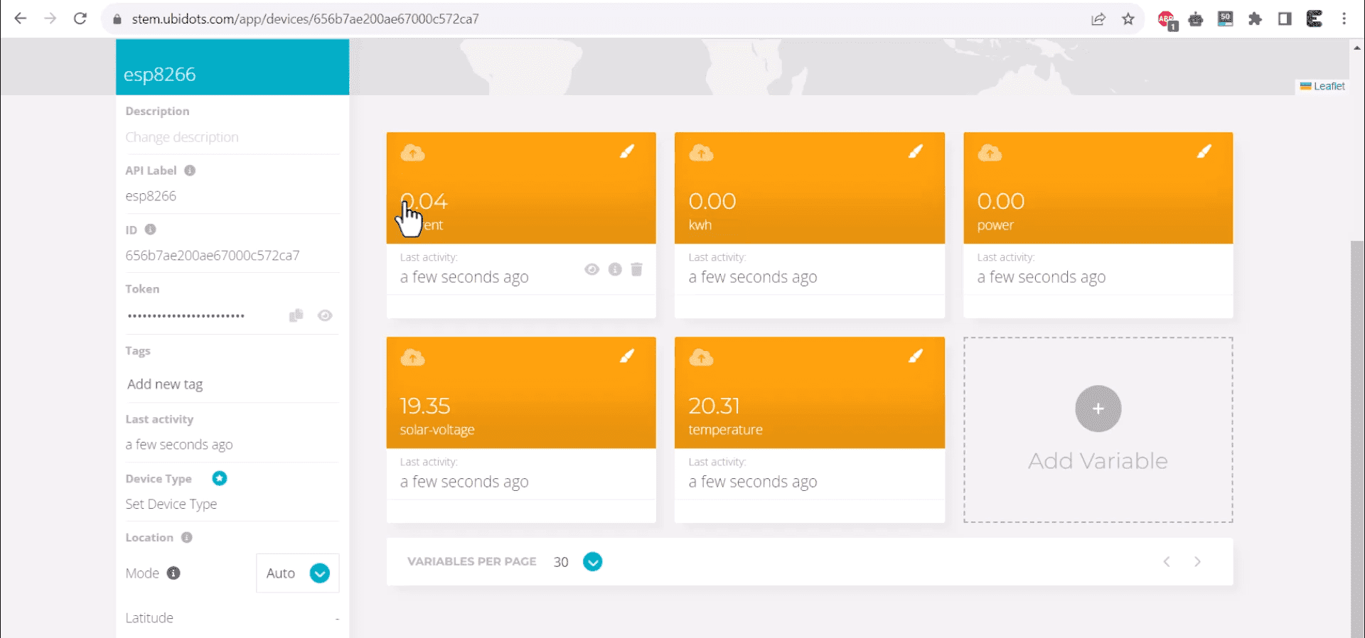
You can designate the units for various solar-related measurements as follows:
| Measurement | Unit |
|---|---|
| Solar Voltage | Volts (V) |
| Current | Milliamperes (mA) |
| Power | Milliwatts (mW) |
| Energy Consumption | Kilowatt-hours (kWh) |
| Temperature | Degrees Celsius (°C) |
You may change the color of the logged variables for proper differentiation.
 Now the variable part is done, therefore we need to create a dashboard for proper visualization.
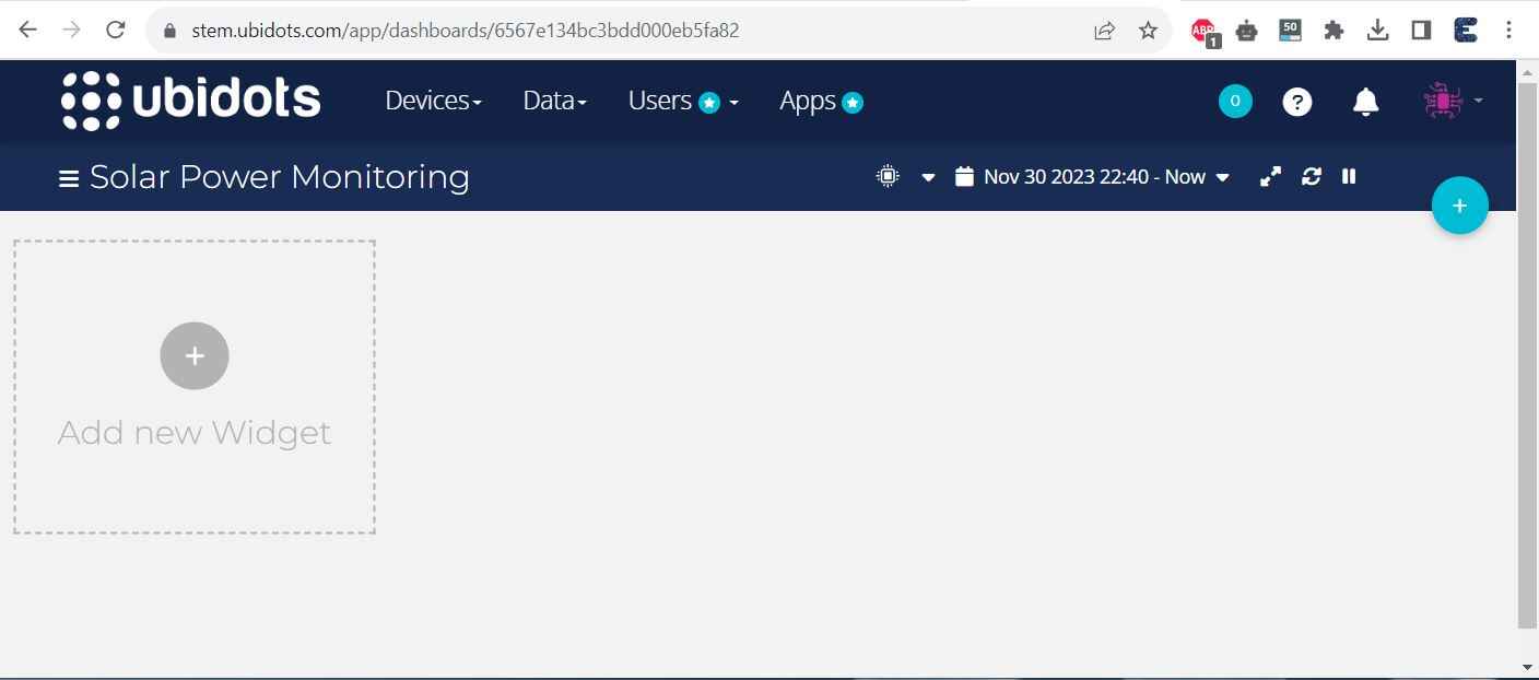
Therefore go to the dashboard part now.
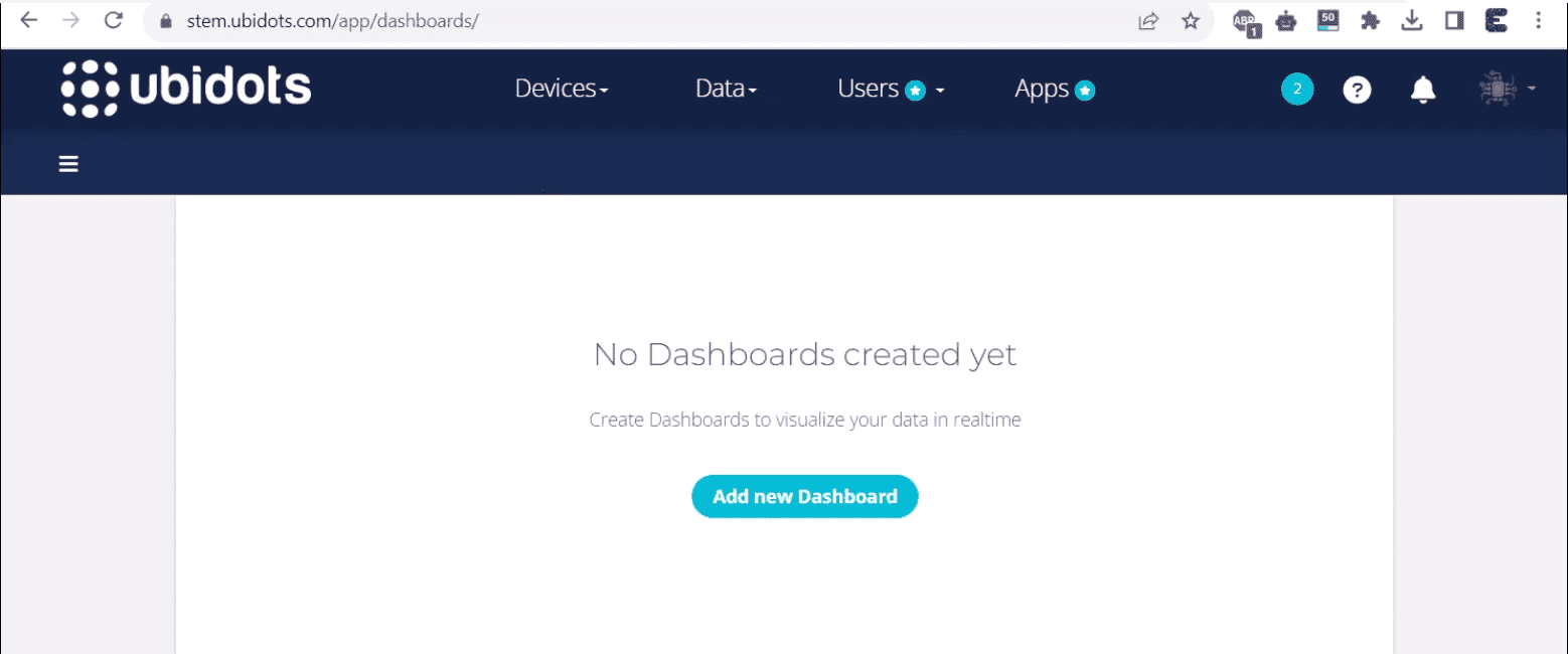
Currently, no dashboard has been created. Therefore click on Add new Dashboard and name the dashboard as “IoT Solar Panel Monitoring System”.
Then create a dashboard using the instructions on the dashboard. Finally, the dashboard will look something like this.
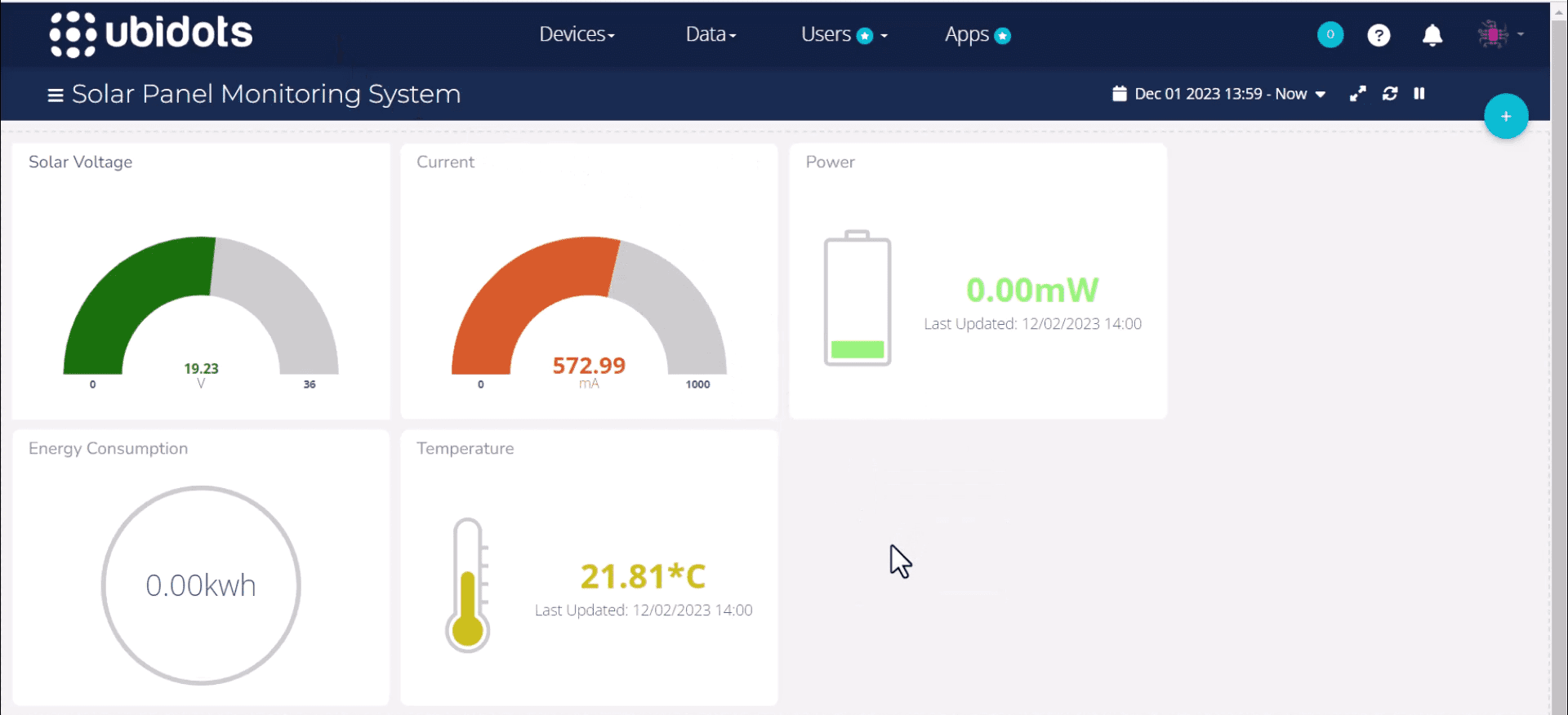
You may make the dashboard better by changing the color or widget. Finally, connect some load to the output terminal of the PCB Board. I used a DC Motor for this purpose.

The dashboard showed a spike in Current and Power values as soon as the load was connected.
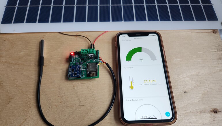
The same visualization can also be observed on a Mobile dashboard. Hence this is how you can build your own IoT Solar Panel Monitoring System with ESP8266 & MQTT and monitor Solar Panel online.
Video Tutorial & Guide

 & Live Dashboard")


1 Comment
Can you add links to the shopping list, like you did in the basic version please? I’m struggling to locate all the components.