

Overview
In this project we will develop an IoT Based Solar Power Monitoring System using ESP32 WiFi Module. The ESP32 connects to the WiFi Network and uploads the Solar Sensing parameters like Solar Panel Voltage, Temperature, and Light Intensity on Thingspeak Server.
Solar power plants need Solar Panel Monitoring for optimum power output. Solar energy is the future of the energy industry. Countries all around the world are focusing on renewable and clean sources of energy. Sunlight is the most abundant resource available everywhere and each day. We can use Sunlight to generate electricity which is pollution free. There are continuous research and innovations going on to improve the efficiency of solar cells, reduce the cost of manufacturing solar panels and improve power distribution from solar plants. This project is also aimed at innovation to improve the efficiency of solar panels.

The project allows the monitoring power output of a solar panel, incident light intensity, and the operating temperature using an ESP32 WiFi + BLE Microcontroller. The Solar Panel and the sensors are precisely connected to the ESP32 controller which supervises the panels and loads. Thus, users can view the voltage, temperature, and Solar Irradiance online from any part of the world.
There are a wide variety of possible uses of this technology, including Solar cities, Smart villages, Microgrids, and Solar street lighting.
Bill of Materials
We need the following components to build an IoT Based Solar Power Monitoring System. You can purchase all the components from Amazon.
| S.N. | Components | Quantity | Purchase Link |
|---|---|---|---|
| 1 | ESP32 WiFi Module | 1 | Amazon | AliExpress |
| 2 | Solar Panel (3-25V) | 1 | Amazon | AliExpress |
| 3. | Voltage Sensor Module | 1 | Amazon | AliExpress |
| 4 | LM35 Temperature Sensor | 1 | Amazon | AliExpress |
| 5 | LDR | 1 | Amazon | AliExpress |
| 6 | 16x2 I2C LCD Display | 1 | Amazon | AliExpress |
| 7 | Resistor 2.2K | 1 | Amazon | AliExpress |
| 8 | Zero PCB/Vero Board | 1 | Amazon | AliExpress |
| 9 | Micro-USB Data Cable | 1 | Amazon | AliExpress |
0-25V Voltage Sensor Module
The Voltage Sensor Module is a simple but very useful module that uses a potential divider to reduce an input voltage by a factor of 5. The 0-25V Voltage Sensor Module allows you to use the analog input of a microcontroller to monitor voltages much higher than it is capable of sensing.

The Voltage Sensor is basically a Voltage Divider consisting of two resistors with resistances of 30KΩ and 7.5KΩ i.e. a 5 to 1 voltage divider. Hence the output voltage is reduced by a factor of 5 for any input voltage. The internal circuit diagram of the Voltage Sensor Module is given below.

For more details on this sensor refer to Voltage Sensor Interfacing guide in one of our previous post.
LM35 Temperature Sensor
The LM35 series are precision integrated-circuit temperature devices with an output voltage linearly proportional to the Centigrade temperature. It has an advantage over linear temperature sensors calibrated in Kelvin, as the user is not required to subtract a large constant voltage from the output to obtain convenient Centigrade scaling.

The LM35 device does not require any external calibration or trimming to provide typical accuracies of ±¼°C at room temperature and ±¾°C over a full −55°C to 150°C temperature range.
For more info on LM35 Temperature Sensor refer to LM35 Interfacing guide in one of our previous post.
Light Dependent Resistor (LDR)
Light Dependent Resistor or LDR or Photoresistors are electronic components that are often used in electronic circuit designs where it is necessary to detect the presence or the level of light.
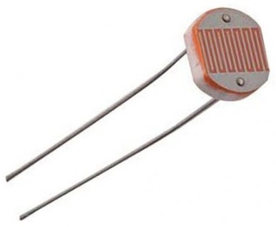
LDRs are very different from other forms of resistor like the carbon film resistor, metal oxide film resistor, metal film resistor, and the like that are widely used in other electronic designs. They are specifically designed for their light sensitivity and the change in resistance this causes.

Block Diagram of IoT Solar Power Monitoring System
Let us take a look at a block diagram of IoT Based Solar Power Monitoring System with ESP32. The ESP32 is interfaced with the voltage Sensor, LM-35 temperature sensor, and LDR sensor. These three sensors are used to monitor the power output, temperature, and incident light intensity respectively.
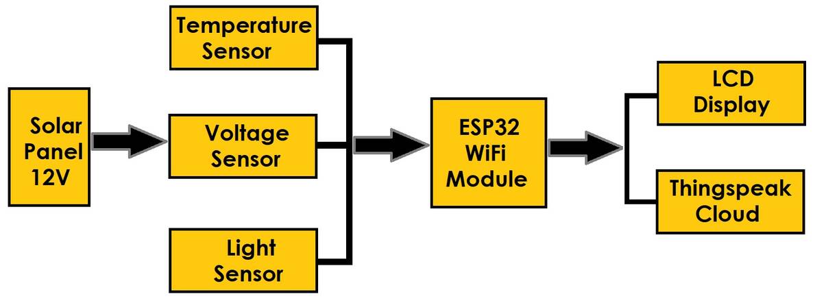
A character LCD is also interfaced with the board for real-time display of the measured parameters. The solar panels are assumed to be installed with internet hotspots at their installation site. The ESP32 not only displays the measured parameters on the LCD screen but also sends the measured values to the Thingsepak cloud server.
The voltage, temperature & light parameters can be monitored in real-time and logged on Thingspeak Server for analytics and performance evaluation.
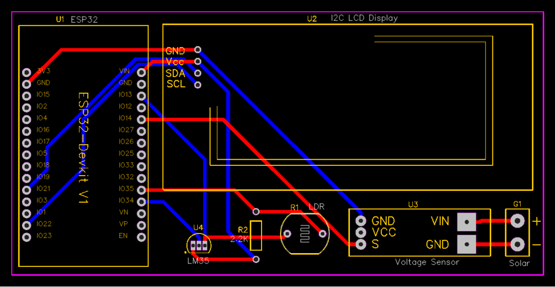
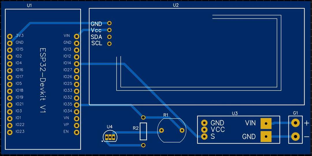
Circuit: IoT Based Solar Power Monitoring System with ESP32
Let us see the schematic for IoT Based Solar Power Monitoring System with ESP32 WiFi Module.

The ESP32 is the main controller for the entire project. There are 3 sensors that directly connect to the GPIO pin of ESP32. The 3 sensors are Voltage Sensor (0-25V), LM35 Temperature Sensor & LDR Sensor.
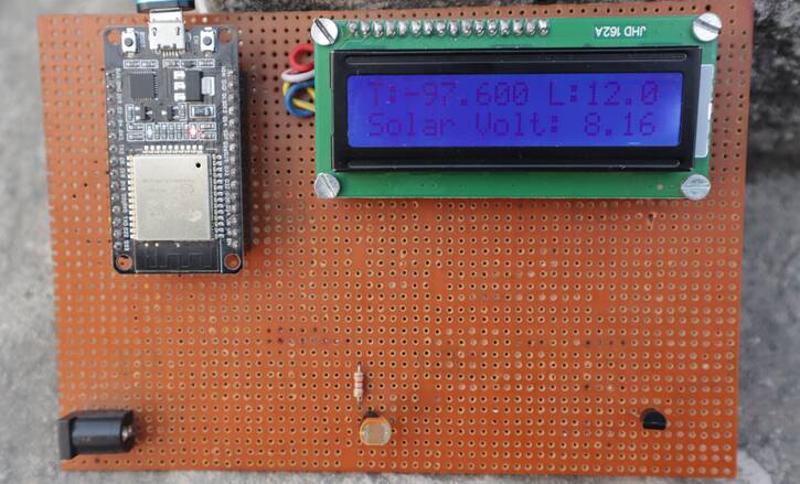
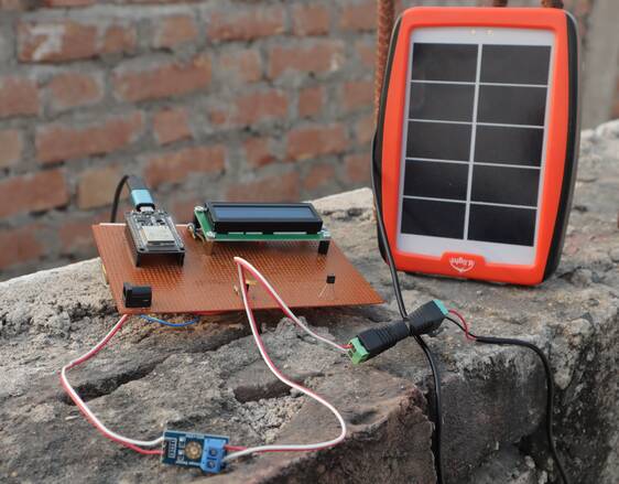
Connect the input of Voltage Sensor to GPIO14 of ESP32 Board. On the other side of the Voltage, the Sensor connects the Solar Panel with a voltage range between 3V-25V as the voltage sensor’s maximum sensing capacity is 25V only. Similarly, connect the input of the LM35 temperature sensor to the GPIO34 of ESP32. The LDR requires a resistor of 2.2K in series to measure the analog voltage fed to the ESP32 Analog pin. The LDR input pins connect to the GPIO35 of ESP32.
Connect the SDA & SCL pin of I2C LCD Display to GPIO21 & GPIO22 respectively. You can power the LCD Display, & LM35 via 5V pin of ESP32.

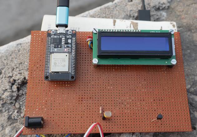
Project PCB Gerber File & PCB Ordering Online
If you don’t want to assemble the circuit on a zero PCB and you want PCB for the project, then here is the PCB for you. I used EasyEDA to design the PCB. The PCB Board for IoT Solar Power Monitoring System looks something like below.
The Gerber File for the PCB is given below. You can simply download the Gerber File and order the PCB from ALLPCB at 1$ only.
You can use this Gerber file to order high quality PCB for this project. To do that visit the ALLPCB official website by clicking here: https://www.allpcb.com/.

You can now upload the Gerber File by choosing the Quote Now option. From these options, you can choose the Material Type, Dimensions, Quantity, Thickness, Solder Mask Color and other required parameters.

After filling all details, select your country and shipping method. Finally you can place the order.
You can assemble the components on the PCB Board.
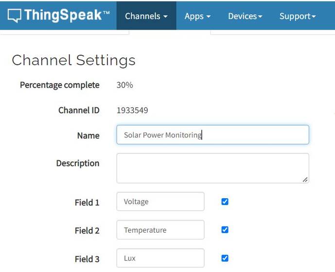
Setting up Thingspeak Server
ThingSpeak provides very good tool for IoT based projects. By using the ThingSpeak site, we can monitor our data and control our system over the Internet, using the Channels and web pages provided by ThingSpeak. So first you need to sign up for ThingSpeak. So visit https://thingspeak.com and create an account.

Then create a new channel and create three variables as voltage, temperature & lux.
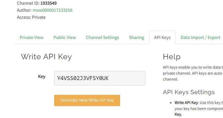
Then create the API keys. This key is required for programming modifications and receiving data from ESP32 WiFi Module.
Now click on channels so that you can see the online data streaming.
Source Code/Program
The code for IoT Based Solar Power Monitoring System with ESP32 is simple & can be written on Arduino IDE.
The code requires I2C LCD Library for compilation.
From the following lines, you need to change the Thingspeak API Key, WiFi SSID & Password.
|
1 2 3 |
String apiKey = "***************"; const char* ssid = "**************"; // Enter your WiFi Network's SSID const char* pass = "**************"; // Enter your WiFi Network's Password |
Now you can upload the following code to ESP32 Board.
|
1 2 3 4 5 6 7 8 9 10 11 12 13 14 15 16 17 18 19 20 21 22 23 24 25 26 27 28 29 30 31 32 33 34 35 36 37 38 39 40 41 42 43 44 45 46 47 48 49 50 51 52 53 54 55 56 57 58 59 60 61 62 63 64 65 66 67 68 69 70 71 72 73 74 75 76 77 78 79 80 81 82 83 84 85 86 87 88 89 90 91 92 93 94 95 96 97 98 99 100 101 102 103 104 105 106 107 108 109 110 111 112 113 114 115 116 117 118 119 120 121 122 123 |
#include <WiFi.h> #include <LiquidCrystal_I2C.h> LiquidCrystal_I2C lcd(0x27, 16, 2); const int lm35_pin = 34; const int voltageSensor = 14; float vOUT = 0.0; float vIN = 0.0; float R1 = 30000.0; float R2 = 7500.0; int value = 0; float RLDR; float Vout; float Lux; String apiKey = "***************"; const char* ssid = "**************"; // Enter your WiFi Network's SSID const char* pass = "**************"; // Enter your WiFi Network's Password const char* server = "api.thingspeak.com"; WiFiClient client; void setup() { Serial.begin(115200); lcd.begin(); lcd.backlight(); lcd.setCursor(0, 0); lcd.print("Welcome To"); lcd.setCursor(0, 1); lcd.print("Our Projects"); delay(2000); lcd.clear(); Serial.println("Connecting to "); Serial.println(ssid); WiFi.begin(ssid, pass); while (WiFi.status() != WL_CONNECTED) { delay(100); Serial.print("*"); } Serial.println(""); Serial.println("WiFi connected"); } void loop() { int temp_adc_val; float temp_val; float tempF = temp_val * 9 / 5 + 32; temp_adc_val = analogRead(lm35_pin); /* Read Temperature */ temp_val = (temp_adc_val * 4.88); /* Convert adc value to equivalent voltage */ temp_val = (temp_val / 10); /* LM35 gives output of 10mv/°C */ lcd.setCursor(0, 0); lcd.print("T:-"); lcd.print(tempF); Serial.print("Temperature = "); Serial.print(tempF); delay(1000); value = analogRead(voltageSensor); vOUT = (value * 5.0) / 3724.0; vIN = vOUT / (R2 / (R1 + R2)); int sensorValue = analogRead(35); Vout = (sensorValue * 0.0048828125); RLDR = (10000.0 * (3 - Vout)) / Vout; Lux = (RLDR / 500); lcd.setCursor(10, 0); lcd.print("L:"); lcd.print(Lux); delay(1000); lcd.setCursor(0, 1); lcd.print("Solar Volt:"); lcd.setCursor(12, 1); lcd.print(vIN); if (client.connect(server, 80)) { String postStr = apiKey; postStr += "&field1="; postStr += String(temp_val); postStr += "&field2="; postStr += String(vIN); postStr += "&field3="; postStr += String(Lux); postStr += "\r\n\r\n\r\n"; client.print("POST /update HTTP/1.1\n"); delay(100); client.print("Host: api.thingspeak.com\n"); delay(100); client.print("Connection: close\n"); delay(100); client.print("X-THINGSPEAKAPIKEY: " + apiKey + "\n"); delay(100); client.print("Content-Type: application/x-www-form-urlencoded\n"); delay(100); client.print("Content-Length: "); delay(100); client.print(postStr.length()); delay(100); client.print("\n\n"); delay(100); client.print(postStr); delay(100); } client.stop(); Serial.println("Sending...."); delay(15000); } float mapfloat(float x, float in_min, float in_max, float out_min, float out_max) { return (x - in_min) * (out_max - out_min) / (in_max - in_min) + out_min; } |
Testing IoT Based Solar Power Monitoring System with ESP32
After uploading code, the ESP32 will connect to the WiFi Network. Then it will establish a connection with Thingspeak Server using the API Key.
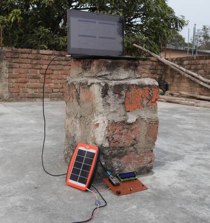
At the same time, you can see the Solar Power measuring parameters on the LCD Display.
To check the proper working of the project, you can take the Solar Panel to a dark room or completely under the sun. There will be massive changes in measuring parameters.
Similarly, go to the private view of the Thingspeak Server, and you will see the parameters logged in the graphical format along with time intervals.
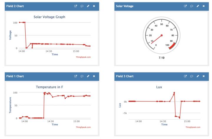
The data only uploads at an interval of 15 seconds on the Thingspeak Server. You may change the interval to 30 seconds or 1 minute or more according to your requirement.
Video Tutorial & Guide

This project can be modified at the best level using some Solar Charging algorithm called MPPT Charge Controller to increase the efficiency of the Solar Panel output power.


12 Comments
come posso fare per cambiare i parametri nel codice per leggere la temperatura in C° (celsius) ? grazie
eccellente progetto 😉
I’ve got this running on a breadboard but I’ve also purchased 5 PCBs. Could you do a video showing how to assemble the PCB? I’m not clear on how to mount the LCD or the Voltage Sensor.
The LCD and voltage sensor can be connected using any jumper wires.
These components don’t get soldered to the PCB?
What does the mapfloat function, at the bottom of the sketch, do? I don’t see it called anywhere in the sketch.
What does the function mapfloat do? I don’t see it used in the sketch at all. It’s at the bottom of the sketch.
It is used for mapping the float value to convert into percentage.
On the PCB, why is pin 3 of the LM35 going to pin 13 of the ESP32?
What program was used to create the gerber files?
Easyeda software
Would you share the Easyeda schematic that you created the gerber files from?
Excelente proyecto, me encanto !!!