

Overview
In this IoT project, we will control a NeoPixel RGB LED Strip using Raspberry Pi Pico W & Adafruit IO. MicroPython has a built-in library for controlling NeoPixels. Together with the WiFi-capable Raspberry Pi Pico W, we can control NeoPixel RGB LED Strip over the Internet.
The WS2812 RGB LED Strip also called NeoPixels can show beautiful light colors. The Neopixel RGB LED has 3 LEDs inside which when mixed in some proportions can produce any color. Moreover, NeoPixels are also addressable which means if we chain multiple NeoPixels together, we are able to control individual NeoPixels by using their own addresses.
In this tutorial, we will use a popular IoT platform called Adafruit IO. Adafruit IO is a platform designed to display, respond, and interact with IoT project data. The dashboards allow users to visualize data and control Adafruit IO connected projects from any modern web browser using widgets such as charts, sliders, and buttons.
This tutorial covers:
- MicroPython usage to control NeoPixel RGB LED Strio
- How to get data from Adafruit IO via its REST APIs
- How to use the data from Adafruit IO to control NeoPixel RGB LED
Components Required
We need the following components for this project. You can purchase all these components from SunFounder Amazon link which consists of the necessary sensors & modules along with 200+ components.
- Raspberry Pi Pico W – 1
- RGB LED Strip with – 1
- Jumper Wires – 10
- Breadboard – 1
- Micro-USB Cable – 1
Circuit & Hardware Setup
Let us set up the hardware for controlling Neopixel RGB LED Strip with Raspberry Pi Pico W & Adafruit IO. The connection is very simple. The NeoPixel LED Strip is addressable, we only need one digital pin to control the entire chain of LEDs.
![]()
Connect the 5V, GND, and Output pin of NeoPixel RGB LED Strip to VSYS, GND & GP0 Pin of Raspberry Pi Pico W respectively. The total number of RGB LED used in this guide is 8.
If you need to use more than a few NeoPixels, you should use an external power rather than the power pin of the microcontroller. This is because NeoPixels actually draw quite a lot of power.
![]()
Setting up Adarfuit IO Feeds & Dashboard
Before working on the project, you need an Adafruit account first. Visit io.adafruit.com and follow the instructions to create a free account.
Now we need to create 3 feeds. To do that click on Feeds tab.
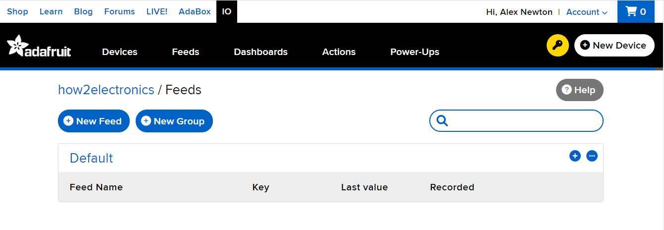
Click on “+New Feed” & give the feed name as Red and click on create.
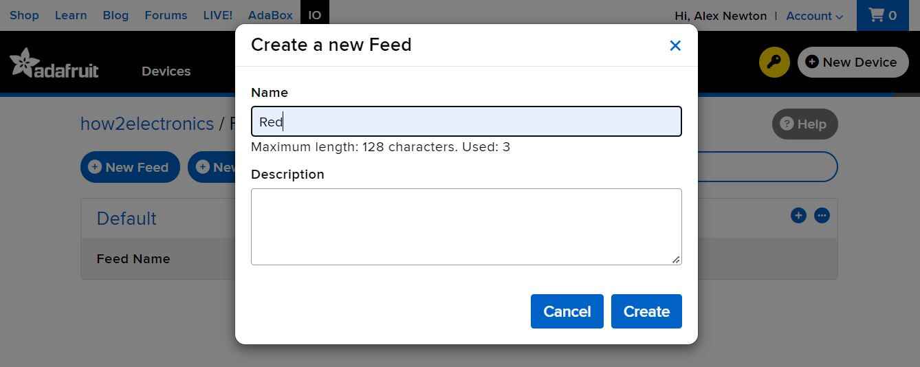
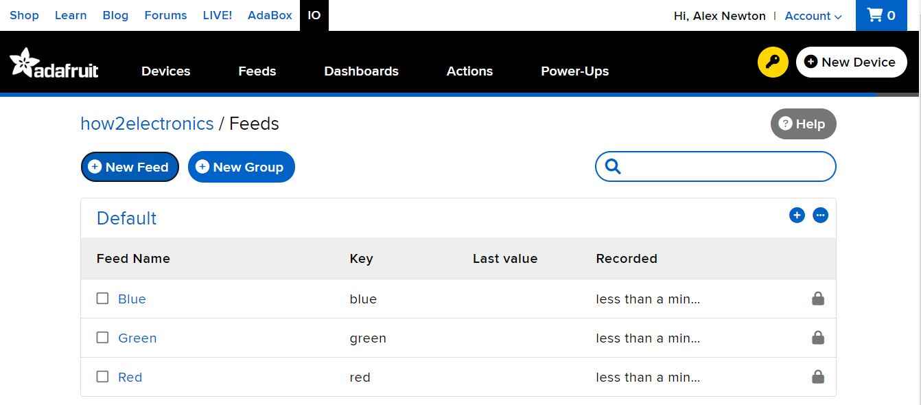
Create 3 different feeds with name like Red, Green & Blue.
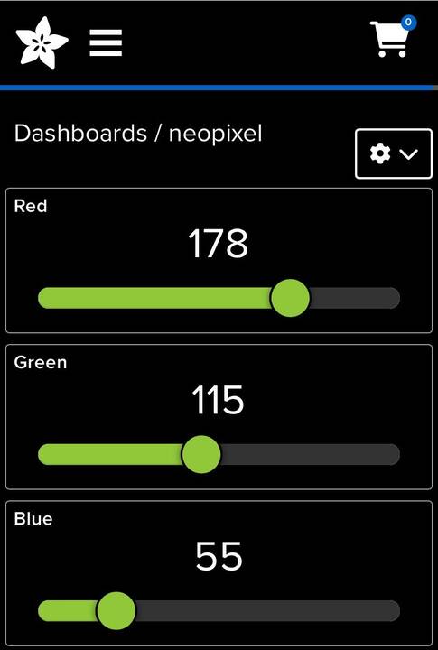
Now we need to set up the Dashboards. To do that click on the Dashboards tab.
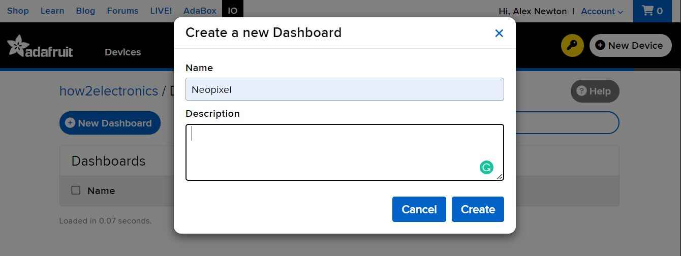
Give the name to the Dashboard as NeoPixel and click on Create.
Finally a dashboard called NeoPixel is created.
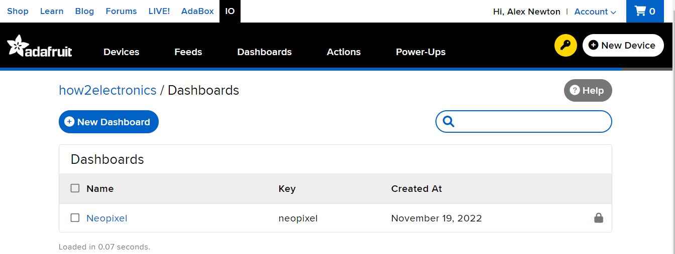
Click on the NeoPixel, so that the Dashboard will open.
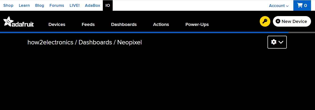
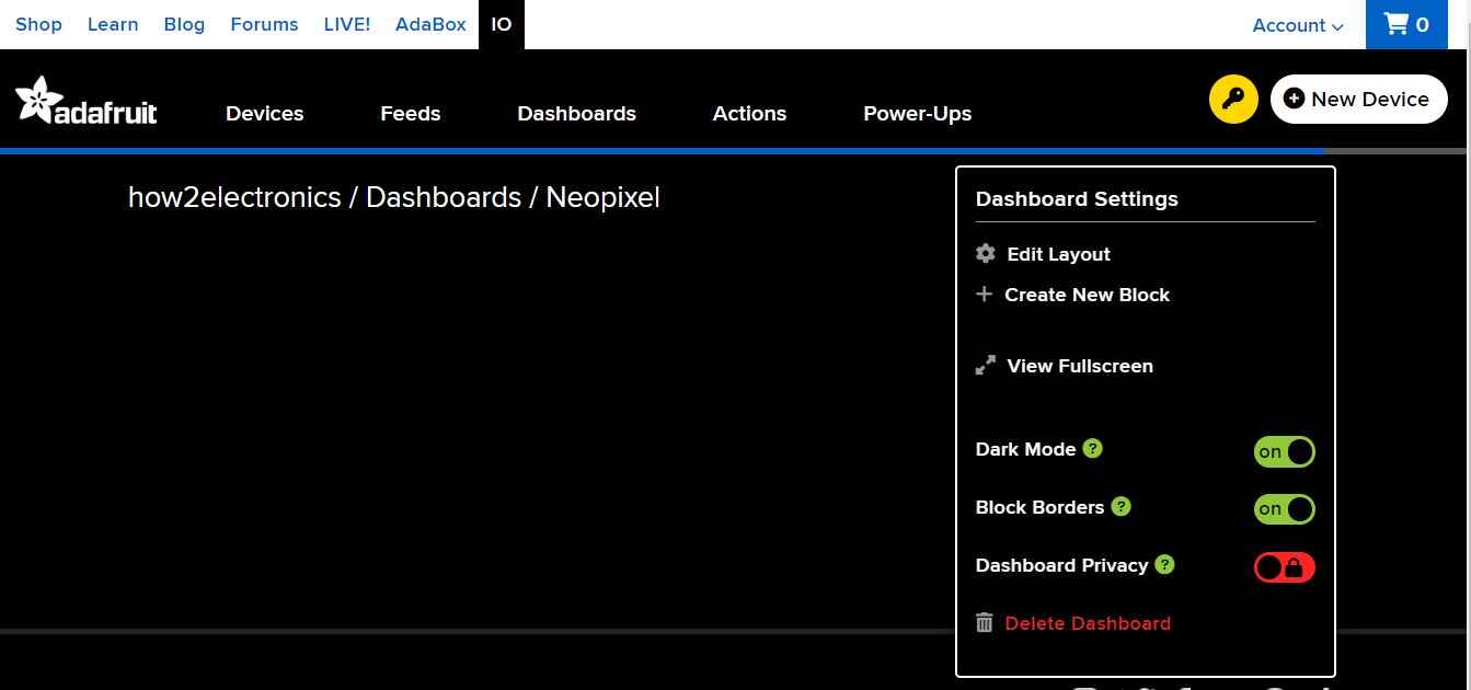
Click on the Setting sign of the dashboard. Here you will see multiple options like edit layout, create new layout along with Mode, and Block Borders setup.
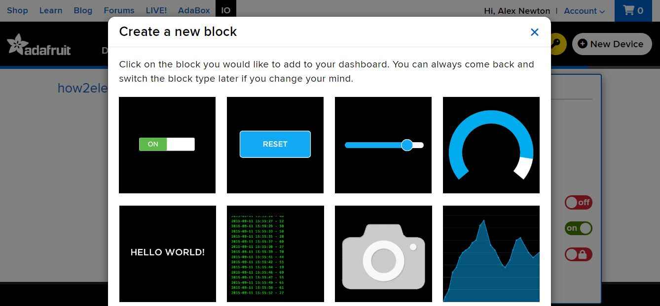
Click on ‘Create a New Block’ & from the list select a ‘Slider’.
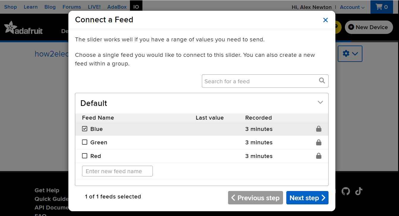
Connect to a feed called ‘Blue’ and then click on ‘Next step’.
In the block setting the slider minimum and the maximum value is set to 0 and 255 respectively. Similarly, the slider step size is 1 and the decimal point is 0. Then click on Create block.

Similarly create the two remaining blocks in the same way and with the same settings. Finally, your slider dashboard for R, G & B is ready.
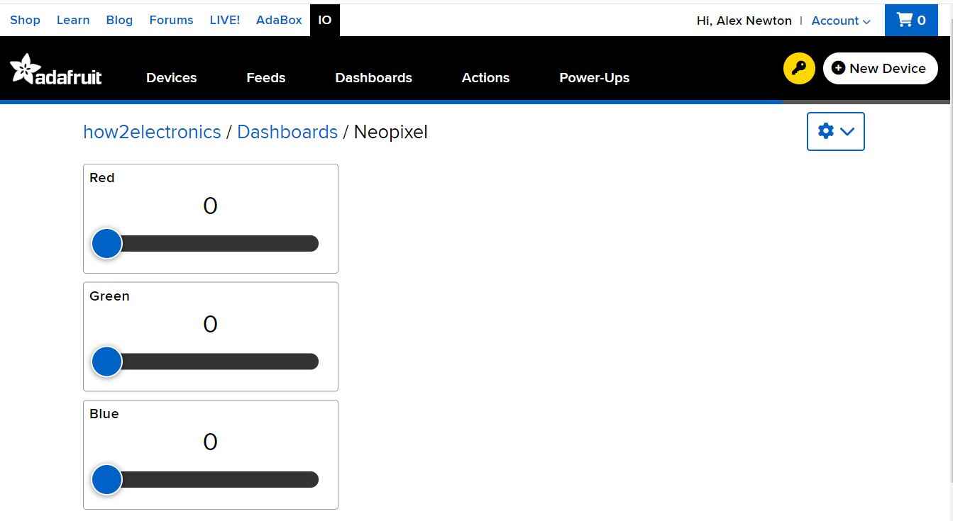
You can now manipulate the data with the sliders. The values of the three feeds will be updated accordingly.
Click on the Key symbol on the top right of the dashboard and from here you need to copy the ‘username’ and ‘Adafruit IO Key’.

Finally the software setup is complete and we need to move to the programming part.
MicroPython Code
Now let us see the MicroPython Code to Control WS2812 NeoPixel RGB LED Strip with Raspberry Pi Pico & Adafruit IO. It is very easy to use REST APIs with Raspberry Pi Pico W and MicroPython to get data from the Adafruit IO.
Open your Thonny IDE and open a New Tab. Then you can paste the code below. You need to make some changes to the following lines of the code before running it.
|
1 2 3 4 |
wlan.connect("SSID","Password") aio_key = "Adafruit IO Key" username = "Adafruit IO Username" |
Replace the WiFi SSID and Password with your WiFi SSID Name and Password. Similarly change the Adafruit IO Key and also the username.
|
1 2 3 4 5 6 7 8 9 10 11 12 13 14 15 16 17 18 19 20 21 22 23 24 25 26 27 28 29 30 31 32 33 34 35 36 37 38 39 40 41 42 43 44 45 46 47 48 49 50 51 52 53 54 55 56 57 58 |
from machine import Pin from neopixel import NeoPixel from time import sleep import network import urequests as requests import ujson wlan = network.WLAN(network.STA_IF) wlan.active(True) wlan.connect("SSID","Password") # Adafruit IO authentication aio_key = "Adafruit IO Key" username = "Adafruit IO Username" headers = {'X-AIO-Key': aio_key, 'Content-Type': 'application/json'} # Don't forget the NeoPixels! np = NeoPixel(Pin(0), 8) feed_names = ['red', 'green', 'blue'] rgb_values = {'red': 0, 'green': 0, 'blue': 0} # connect the network wait = 10 while wait > 0: if wlan.status() < 0 or wlan.status() >= 3: break wait -= 1 print('waiting for connection...') time.sleep(1) # Handle connection error if wlan.status() != 3: raise RuntimeError('wifi connection failed') else: print('connected') ip=wlan.ifconfig()[0] print('IP: ', ip) def create_URL(feedname): url = "https://io.adafruit.com/api/v2/" + username + "/feeds/" + feedname + "/data/last" return url try: while True: for color in feed_names: response = requests.get(create_URL(color), headers=headers) parsed = ujson.loads(response.text) value = int(parsed['value']) rgb_values[color] = value print(value) for i in range(8): np[i] = (rgb_values['red'], rgb_values['green'], rgb_values['blue']) np.write() except KeyboardInterrupt: for i in range(8): np[i] = (0, 0, 0) np.write() time.sleep(0.5) |
Save the file to file to Raspberry Pi Pico W and name it as Main.py. You can now run the code.
Code Explanation
First we import the necessary library required to control RGB LED Strip with Raspberry Pi Pico W library.
|
1 2 3 4 5 6 |
from machine import Pin from neopixel import NeoPixel from time import sleep import network import urequests as requests import ujson |
The following lines contains the information to connect the Raspberry Pi Pico W to WiFi Network using SSID & Password.
|
1 2 3 4 5 6 7 |
wlan.active(True) wlan.connect("SSID","Password") # Adafruit IO authentication aio_key = "2e0cc5a*************a0ab70" username = "*****************" headers = {'X-AIO-Key': aio_key, 'Content-Type': 'application/json'} |
Using the Adafruit IO username and Rest API key, the Raspberry Pi Pico W will establish the connection with Adafruit IO Dashboard.
The we define the Neopixel digital pin as 0 and total number of LED strip as 8.
|
1 2 3 |
np = NeoPixel(Pin(0), 8) feed_names = ['red', 'green', 'blue'] rgb_values = {'red': 0, 'green': 0, 'blue': 0} |
The array feed_names contains the names of the feeds that we have created in Adafruit IO, and the dictionary rgb_values is used for storing the values downloaded from Adafruit IO.
The Raspberry Pi Pico will connect to the WiFi Network & print the IP Address.
|
1 2 3 4 5 6 7 8 9 10 11 12 13 14 15 16 |
# connect the network wait = 10 while wait > 0: if wlan.status() < 0 or wlan.status() >= 3: break wait -= 1 print('waiting for connection...') time.sleep(1) # Handle connection error if wlan.status() != 3: raise RuntimeError('wifi connection failed') else: print('connected') ip=wlan.ifconfig()[0] print('IP: ', ip) |
Since we need to get the values of three feeds, and each feed has its own URL. Therefore we create a function for making the required URL.
|
1 |
url = "https://io.adafruit.com/api/v2/" + username + "/feeds/" + feedname + "/data/last" |
In the main loop, for each of the feeds ‘red’, ‘green’ and ‘blue’, we send an HTTP GET request to Adafruit IO with the URL made by the create_URL function and the headers dictionary.
|
1 |
response = requests.get(create_URL(color), headers=headers) |
Then, we use the loads function in the ujson library to convert the JSON text received from Adafruit IO into a Python dictionary. This conversion is known as parsing.
|
1 |
parsed = ujson.loads(response.text) |
From the Python dictionary parsed, we get the latest value of the feed (which is a string) and convert it into an integer.
|
1 |
value = int(parsed['value']) |
After saving all the RGB values to the dictionary rgb_values, we can set the color of the NeoPixels accordingly.
Controlling RGB LED Strip with Raspberry Pi Pico W & Adafruit IO
After running the code, the Raspberry Pi Pico W will connect to the WiFi Network using the WiFi SSID & Password. Then it establishes the connection with Adafruit IO using the API Key.
Now you can send commands from Adafruit IO Dashboard with sliding different slides. This will control the color intensity and brightness.
The range of the color is from 0 to 255 for all red, green, and blue. You can slide all three slides to control the RGB Color.
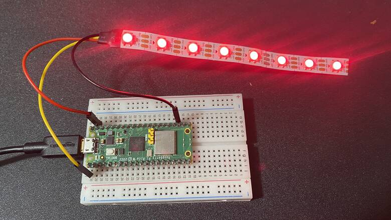
You may generate red color by sliding Red Slider only.
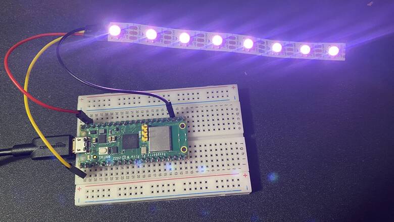
As an example, you may adjust red, green & blue color slider to generate purple color.
The green color brightness intensity can be increased or decreased by adjusting the slider between 0 to 255 and keeping red and blue as 0.

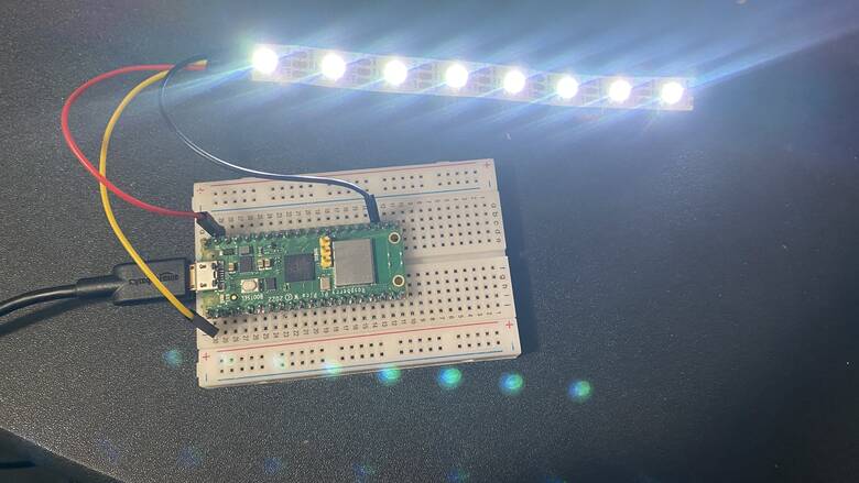
Keeping the red, green & blue color to 255 can produce a pure white color.
You can only turn on the Blue Color LED by sliding the Blue slider.

This is how you can control any NeoPixel RGB LED Strip with Raspberry Pi Pico W & MicroPython Code using Adafruit IO Dashboard.


8 Comments
Getting error in the code …
Keyerror : value
Getting error in the code …
Keyerror : value
I too am getting the KeyError: value. Feed data from Adafruit not coming through?
For whatever reason, deleting the dashboard (but not the feeds themselves) at adafruit seemed to fix the problem KeyError problem but then I ran into the problem of VSYS (5V) not working, so I switched to 3V3 and voila! It worked. But wondering why not with my 5V setup?
I have also met the Keyerror: value problem.
Has somebody found a solution?
Has anyone solved the Keyerror: value problem issue ?.
If you are getting a Keyerror: value error make sure that your username and Adafruit key are in the right lines and not switched.
Worked GREAT! Thank you for the easy to follow tutorial! Now working on how to make it wireless and start up at power.