

Overview
In this project, we will build an IoT Based Smart Exhaust Fan using the ESP32 with Manual Control & Monitoring System. The project focuses on creating a smart exhaust fan system using the ESP32 microcontroller. This system is designed to monitor environmental conditions like gas levels, temperature, and humidity through the MQ-2 Gas/Smoke Sensor and the DHT11 Humidity Temperature Sensor. The data from these sensors is sent to the Blynk Dashboard, allowing for real-time monitoring.
A key feature of this project is the automation of the exhaust fan, which is connected to a 110/220V AC power supply through a relay. The fan’s operation is controlled based on the gas levels detected by the MQ-2 sensor. When high gas levels are sensed, the system automatically turns on the fan to ventilate the area, enhancing safety and air quality.
Additionally, the system provides manual control of the fan via the Blynk Dashboard. This flexibility allows users to manually override the automatic settings, offering personalized control based on individual needs or preferences. This IoT-based solution integrates IoT Smart monitoring and control for an exhaust fan, showcasing the application of IoT technology in home and environmental safety.
Bill of Materials
We need the following components to build this IoT Smart Exhaust Fan. All the components can be purchased from the given links.
| S.N. | Components | Quantity | Purchase Links |
|---|---|---|---|
| 1 | ESP32 WiFi Module | 1 | Amazon | AliExpress | SunFounder |
| 2 | Exhaust Fan | 1 | store.honguan.com |
| 3 | MQ-2 Gas Sensor | 1 | Amazon | AliExpress | SunFounder |
| 4 | DHT11 Humidity Temperature Sensor | 1 | Amazon | AliExpress| SunFounder |
| 5 | 1-Channel Relay Module | 1 | Amazon | AliExpress | SunFounder |
| 6 | Connecting Wires | 30 | Amazon | AliExpress | SunFounder |
| 7 | Micro-USB Cable | 1 | Amazon | AliExpress |
| 8 | Breadboard | 1 | Amazon | AliExpress | SunFounder |
DHT11 Temperature & Humidity Sensor
The DHT11 Temperature & Humidity sensor is a temperature and humidity composite sensor with calibrated digital signal output. It includes a resistive humidity sensing element and an NTC temperature measuring element and is connected to a high-performance 8-bit microcontroller.

Its application-specific digital module acquisition technology and temperature and humidity sensing technology ensure that the product has extremely high reliability and excellent long-term stability.
There is a dedicated post about DHT11 Arduino interfacing in one of our previous articles. You can go through it for more info.
MQ-2 Gas/smoke Sensor
The MQ-2 Gas Sensor is a versatile gas detection sensor capable of detecting a wide range of gases, including butane, propane, methane, hydrogen, and smoke. It comprises a sensitive material that reacts to the presence of gases in the air, changing its resistance as the gas concentration varies. This sensor is typically connected to an analog input of a microcontroller, allowing for the measurement of gas concentration in the air.

The MQ-2 ensures high sensitivity and fast response time to the presence of gases. Its design makes it suitable for various applications, including gas leakage detectors and fire/safety monitors. The sensor’s performance is characterized by its stability and durability, offering reliable readings over a long period. To learn more refer to Arduino MQ-2 Sensor interfacing guide.
110/220V Exhaust AC Fan
The exhaust fan featured in the Honguan store is a 4-inch model designed for efficient ventilation.

It boasts a 100% copper coil motor, ensuring reliable and stable performance. The fan can efficiently move air at a rate of 80 cubic meters per hour and operates quietly at 33 dB, making it suitable for use in various spaces like bathrooms, living rooms, and offices.
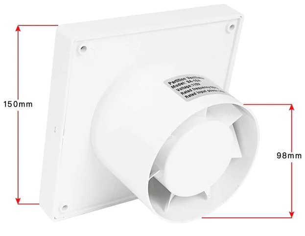
Its construction includes an ABS body, providing corrosion protection and longevity. The fan is also equipped with good heat dissipation capabilities, ensuring durability and efficient operation. The design and construction of this exhaust fan make it a versatile and practical choice for effective air ventilation in both residential and commercial settings.
Hardware Setup & Circuit
Here is the schematic of the IoT ESP32 Smart Exhaust Fan, designed using the Fritzing software. The connections are very simple.

Here we are working with an ESP32 microcontroller and connecting a DHT11 sensor, an MQ-2 gas sensor, and a relay module. Here’s how you can connect these components to your ESP32:
1. DHT11 Temperature and Humidity Sensor
-
- VCC: Connect to a 3.3V pin on the ESP32.
- Data: Connect to GPIO 22 on the ESP32.
- GND: Connect to a ground pin on the ESP32.
2. MQ-2 Gas Sensor
-
- VCC: Connect to 5V on the ESP32.
- GND: Connect to a ground pin on the ESP32.
- A0/: Connect the Analog output (A0) to GPIO 34 on the ESP32.
3. Relay Module
-
- VCC: Connect to the Vin (5V) on the ESP32.
- IN: Connect to GPIO 23 on the ESP32.
- GND: Connect to a ground pin on the ESP32.
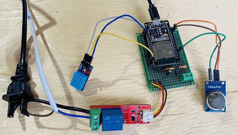
I assembled the circuit on a zero-PCB or a Vero Board. All the connections are done as per circuit diagram.
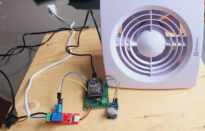
Finally connect a 110V/220V AC Exhaust Fan to the relay as per the circuit diagram. The hardware part of the project is done.
Blynk Dashboard Setup
To monitor the Gas Level, Temperature, and Humidity and also to control and observe the Exhaust Fan status we need to set up the Blynk Dashboard.

To set up the Blynk app for controlling and monitoring your ESP32 project with a gas sensor, DHT11 sensor, and a relay module, follow these steps:
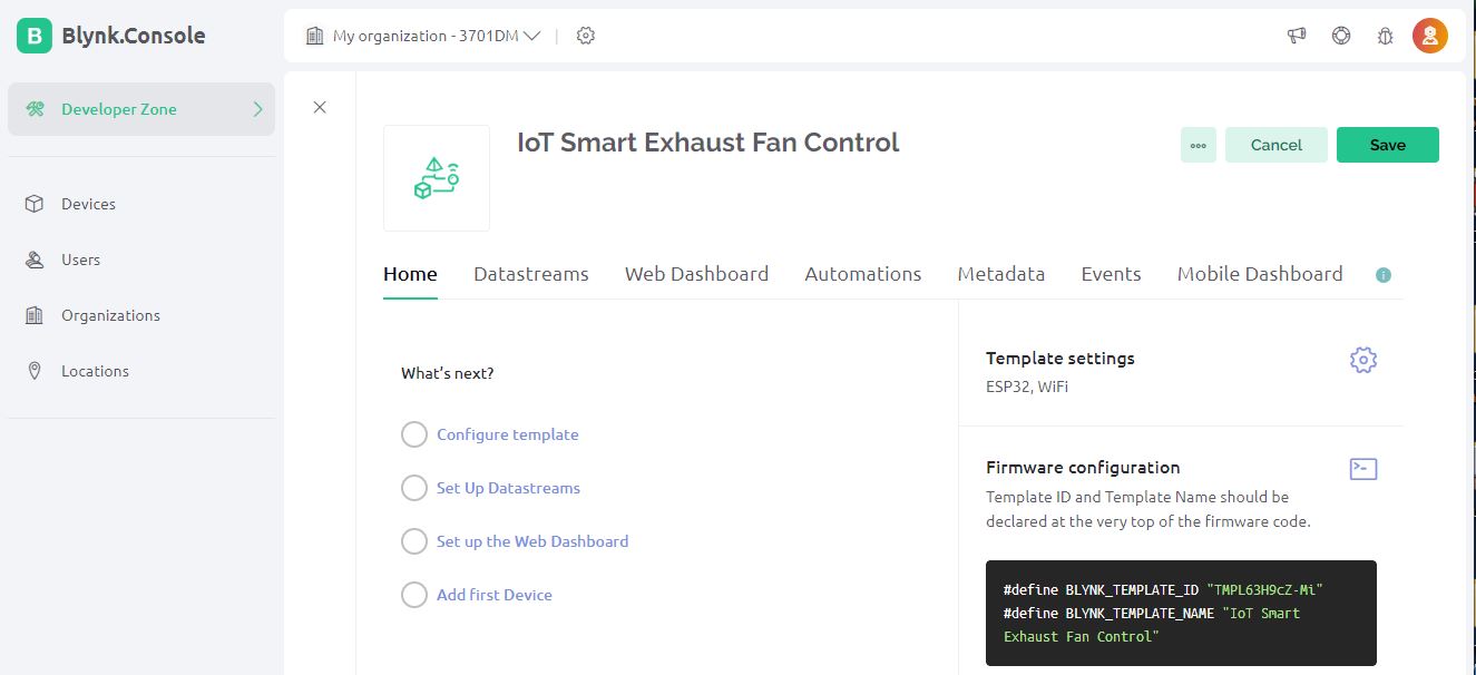
Open the Blynk 2.0 Web Dashboard in a browser or use the mobile app. Create an account or log in if you already have one.
Go to the Templates section and create a new template. Name your template and select ESP32 as the hardware model.
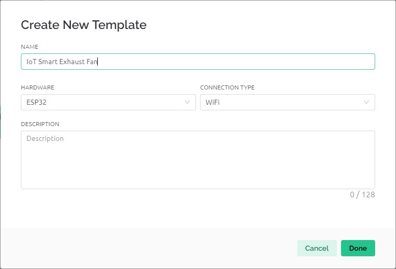
So a new template is created. You need to configure everything from here.
You will need to create data streams for each variable you want to monitor or control.
| Name | Virtual Pin | Data Type | Unit | Min/Max Values |
|---|---|---|---|---|
| Gas Percentage | V0 | Double | % | 0-100 |
| Temperature | V1 | Double | °C | 0-50 |
| Humidity | V2 | Double | % | 0-100 |
| Manual Control | V4 | Integer | – | 0-1 |
| Relay Status | V3 | Integer | – | 0-1 |
For each parameter (gas percentage, temperature, humidity, and relay control), create a data stream:
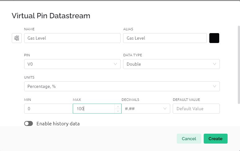
In the same way, create 5 different Data Streams.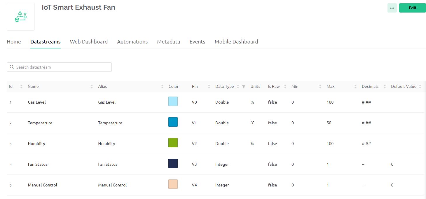
In the Dashboard section, start adding widgets and assign them to the respective data streams you created.
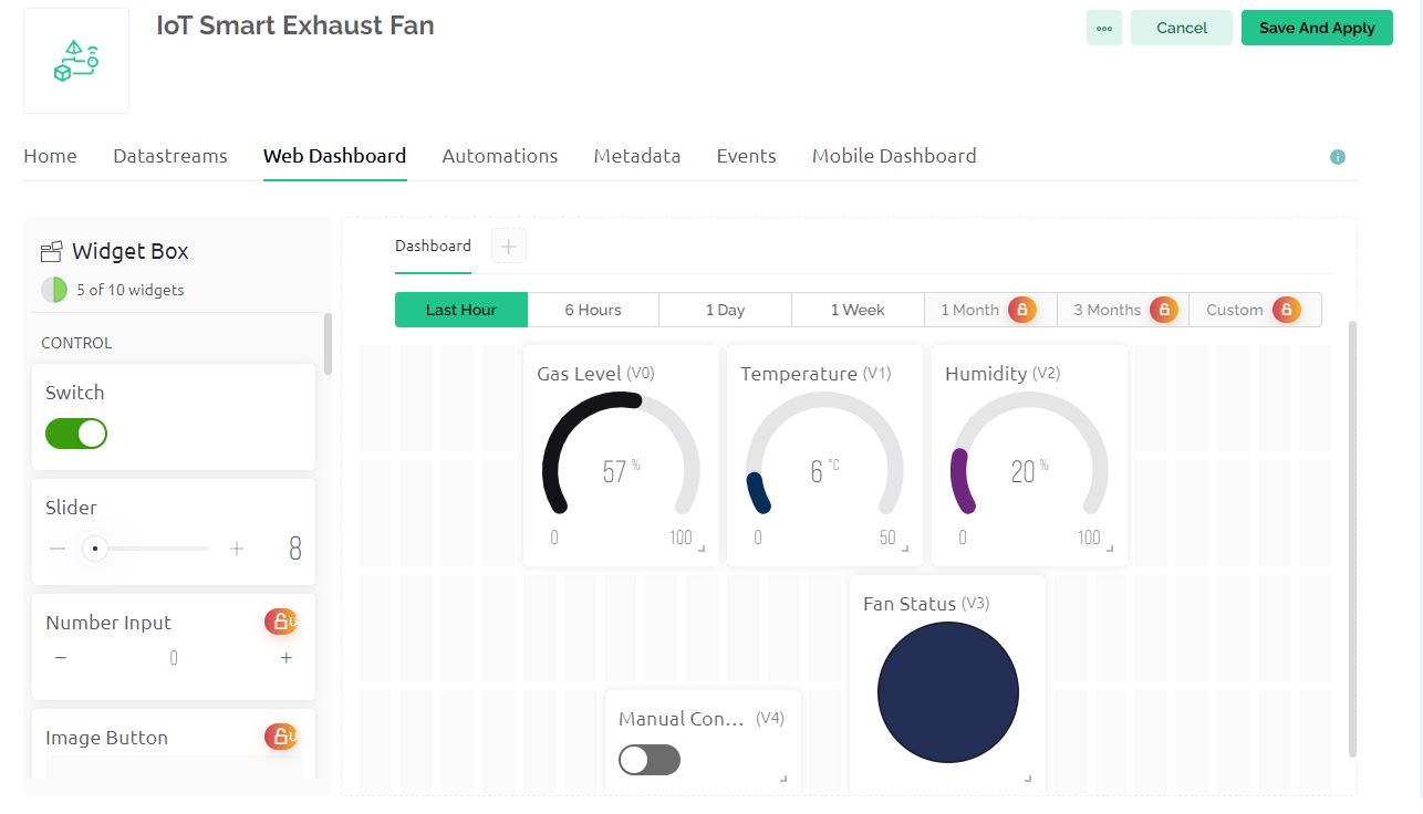
- For displaying data (temperature, humidity, gas percentage), use Value Display or Gauge widgets.
- For controlling the relay, use a Button widget (set it to Switch mode) linked to the Relay Control data stream.
- For displaying the relay status, use an LED widget linked to the Relay Status data stream.
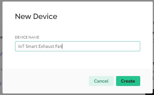
In the Devices section, add a new device using the template you created. Note down the Auth Token provided. This will be used in your ESP32 code.
Source Code/Program
Let us move to the programming part of the IoT Smart Exhaust Fan using ESP32 for Monitoring & Control. It connects to the Blynk platform for remote monitoring and control.
The ESP32 reads data from a DHT11 sensor (temperature and humidity) and an MQ-2 gas sensor, and controls a relay based on the gas levels or manual input from the Blynk app. The sensor data is sent to the Blynk app for real-time monitoring, and the relay can be controlled automatically or manually through the app.
The code requires DHT11 Library and Blynk ESP32 Library. Add these libraries to the Arduino library folder. Then copy the following code and upload it to the ESP32 Board.
|
1 2 3 4 5 6 7 8 9 10 11 12 13 14 15 16 17 18 19 20 21 22 23 24 25 26 27 28 29 30 31 32 33 34 35 36 37 38 39 40 41 42 43 44 45 46 47 48 49 50 51 52 53 54 55 56 57 58 59 60 61 62 63 64 65 66 67 68 69 70 71 72 73 74 75 76 77 78 79 80 81 82 83 84 85 86 87 88 89 90 91 92 93 94 95 96 97 98 99 100 101 102 103 104 105 106 107 108 109 110 111 112 113 114 115 116 |
// Template and device credentials for Blynk #define BLYNK_TEMPLATE_ID "TMPL6YAS5_ss3" #define BLYNK_TEMPLATE_NAME "IoT Smart Exhaust Fan" #define BLYNK_PRINT Serial // Directs Blynk messages to the serial port #include <WiFi.h> // Include WiFi library for ESP32 #include <BlynkSimpleEsp32.h> // Include Blynk ESP32 library #include "DHT.h" // Include DHT sensor library // Blynk and WiFi credentials const char auth[] = "*****************"; // Blynk authentication token const char ssid[] = "*****************"; // WiFi SSID const char pass[] = "*****************"; // WiFi password // Pin configuration #define DHTPIN 22 // DHT sensor pin #define DHTTYPE DHT11 // Type of DHT sensor const int gasSensorPin = 34; // Gas sensor pin const int relayPin = 23; // Relay module pin const int gasThreshold = 20; // Gas level threshold for triggering the relay DHT dht(DHTPIN, DHTTYPE); // Initialize DHT sensor bool manualMode = false; // Flag to track if the relay is in manual mode void setup() { Serial.begin(115200); // Start serial communication at 115200 baud rate dht.begin(); // Initialize DHT sensor Blynk.begin(auth, ssid, pass); // Connect to Blynk using WiFi pinMode(relayPin, OUTPUT); // Set relay pin as output pinMode(gasSensorPin, INPUT); // Set gas sensor pin as input digitalWrite(relayPin, LOW); // Ensure relay is off initially delay(2000); // Wait for 2 seconds before proceeding } // Function to handle manual relay control from Blynk app BLYNK_WRITE(V4) { int relayControl = param.asInt(); // Get value from Blynk app manualMode = (relayControl == 1); // Set manual mode based on app input if (manualMode) { digitalWrite(relayPin, HIGH); // Turn on relay in manual mode } else { digitalWrite(relayPin, LOW); // Turn off relay when exiting manual mode } Blynk.virtualWrite(V3, relayControl); // Update relay status on Blynk } void loop() { Blynk.run(); // Run Blynk int sensorValue = analogRead(gasSensorPin); // Read gas sensor value int gas_percentage = map(sensorValue, 0, 4095, 0, 100); // Convert to percentage float humidity = dht.readHumidity(); // Read humidity from DHT sensor float temperature = dht.readTemperature(); // Read temperature from DHT sensor // Check if sensor readings are valid if (isnan(humidity) || isnan(temperature)) { Serial.println(F("Failed to read from DHT sensor!")); return; } // Print sensor values to the Serial Monitor Serial.print("Humidity: "); Serial.print(humidity); Serial.println("%"); Serial.print("Temperature: "); Serial.print(temperature); Serial.println("°C "); Serial.print("Gas sensor value: "); Serial.println(sensorValue); Serial.print("Gas Percentage: "); Serial.print(gas_percentage); Serial.println("%"); Serial.println(); // Automatic control logic based on gas levels if (!manualMode) { if (gas_percentage > gasThreshold) { digitalWrite(relayPin, HIGH); // Activate relay if gas above threshold Blynk.virtualWrite(V3, HIGH); // Update Blynk app } else { digitalWrite(relayPin, LOW); // Deactivate relay if gas below threshold Blynk.virtualWrite(V3, LOW); // Update Blynk app } } // Send sensor values to Blynk Blynk.virtualWrite(V0, gas_percentage); // Send gas percentage Blynk.virtualWrite(V1, temperature); // Send temperature Blynk.virtualWrite(V2, humidity); // Send humidity delay(1000); // Wait for a second before next loop iteration } |
Testing & Working of IoT Smart Exhaust Fan using ESP32
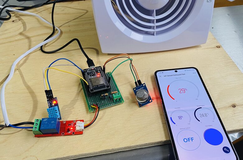
In your IoT Smart Exhaust Fan project, the Blynk app displays real-time data from the DHT11 and MQ-2 sensors connected to the ESP32. Specifically, it shows the Temperature and Humidity readings from the DHT11 sensor. It also shows the Gas Percentage readings from the MQ-2 gas sensor indicating the level of gas in the air.

The relay connected to the ESP32 controls the exhaust fan and operates in two modes:
- Automatic Mode: The relay turns on automatically when the gas percentage exceeds a predefined threshold, indicating high gas concentration. This activates the exhaust fan to clear the air.
- Manual Mode: You can manually control the relay (and thus the exhaust fan) via a button in the Blynk app. This allows you to override automatic control and turn the fan on or off as needed.
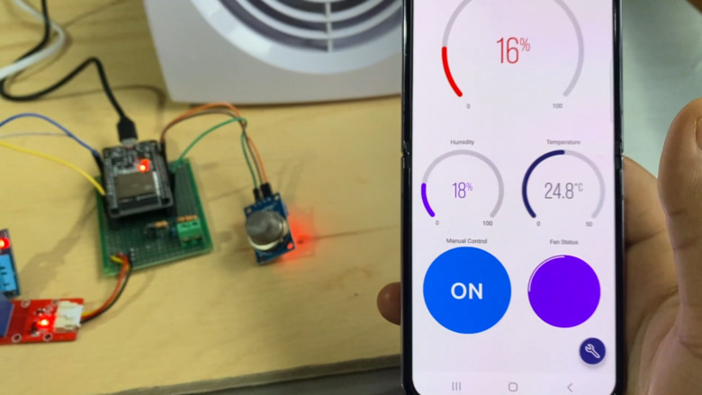
To test your system, particularly the functionality of the MQ-2 gas sensor and the relay, you can introduce a controlled amount of smoke or a safe gas source, such as butane from a lighter (ensuring it is not ignited), near the MQ-2 sensor.
Watch for an increase in the gas percentage reading on the Blynk app; this should automatically activate the relay to turn on the exhaust fan if the system is set to automatic mode.
Additionally, you can evaluate the manual mode functionality by using the Blynk app to independently control the relay, allowing you to turn the exhaust fan on and off at will, irrespective of the gas levels detected.
This setup allows you to monitor environmental conditions and control the exhaust fan effectively, either automatically in response to gas levels or manually through the app.
 & Live Dashboard")


1 Comment
is the fan you used have a power button and is it able to control it speed?