

Introduction
In this tutorial, we will be interfacing DHT11 Humidity Temperature Sensor with Arduino and a 16×2 LCD Display.
Understanding and monitoring environmental conditions are crucial for various applications, ranging from ensuring comfort in living spaces to optimizing conditions in controlled environments. In this project, we introduce a digital humidity and temperature meter, which leverages the capabilities of the DHT11 Humidity & Temperature Sensor in conjunction with an Arduino microcontroller. Not only will you gain insights into the precise temperature and humidity levels of your surroundings, but you’ll also be presented with these metrics on a user-friendly LCD display.
The DHT11 Temperature and Humidity Sensor is an advanced piece of equipment that boasts a calibrated digital signal output, thanks to its integrated temperature and humidity sensor complex. Engineered for utmost reliability, it ensures commendable long-term stability. At the heart of this sensor lies an efficient 8-bit microcontroller. The DHT11 sensor is meticulously designed, featuring a resistive element and a wet NTC temperature measuring component. With attributes like rapid response, stellar anti-interference capabilities, and exceptional value for money, it’s a top choice for DIY enthusiasts and professionals alike.
Components Required
The following are the components required for this tutorial
| S.N. | Components | Quantity | Purchase Link |
|---|---|---|---|
| 1 | Arduino UNO Board | 1 | Amazon | AliExpress | SunFounder |
| 2 | DHT11 Humidity Temperature Sensor | 1 | Amazon | AliExpress| SunFounder |
| 3 | 16X2 I2C LCD Display | 1 | Amazon | AliExpress | SunFounder |
| 4 | Breadboard | 1 | Amazon | AliExpress | SunFounder |
| 5 | Jumper Wires | 7 | Amazon | AliExpress | SunFounder |
DHT11 Humidity Temperature Sensor

The DHT11 is a commonly used and cost-effective sensor that provides readings of both temperature and humidity. Compact and cost-effective, it has become a popular choice in the electronics community for its relative accuracy and ease of integration. Operating on a simple one-wire communication protocol, the DHT11 can be seamlessly interfaced with a variety of microcontrollers, making it suitable for a wide range of applications.
Developed for digital systems, the DHT11 finds its applications in environments where there’s a need to monitor or control atmospheric conditions, such as in smart homes, weather stations, and agricultural monitoring systems.
Features/Specifications of DHT11 Sensor
- Power Supply: Typically operates from 3.3 to 5V DC, making it suitable for interfacing with most microcontrollers.
- Temperature Range: 0°C to 50°C with ±2°C accuracy.
- Humidity Range: 20% to 90% RH (Relative Humidity) with ±5% accuracy.
- Output: Calibrated digital signal. It employs a single-wire communication protocol which simplifies integration with microcontroller systems.
- Sampling Period: Suggested minimum time of 1 second between readings to ensure sensor accuracy.
- Dimensions: Compact size, often available in a 4-pin single-row package.
- Longevity: Offers excellent long-term stability, thanks to its calibrated digital output.
Construction of DHT11 Sensor
- Sensing Elements: The DHT11 integrates two primary components for its operations:
- A thermistor for temperature measurements.
- A capacitive humidity sensor for gauging atmospheric moisture.
- IC Integration: An 8-bit microcontroller reads the outputs from the two sensors and translates them into a format suitable for digital systems.
- Packaging: The sensor elements are often encased in a plastic casing, which ensures protection against environmental factors while still allowing for accurate readings.
Working of DHT11 Sensor

-
- Temperature Measurement: The core of the temperature sensing capability is the thermistor, a type of resistor whose resistance changes with temperature. As the temperature fluctuates, so does the resistance of the thermistor. This variance is then read and converted into temperature values by the onboard microcontroller.

- Humidity Measurement: The capacitive humidity sensor operates by having a dielectric material between two plates. As humidity changes, the dielectric constant of the material changes, leading to a variance in capacitance. This change in capacitance is then read and interpreted as a humidity percentage by the onboard microcontroller.
- Signal Output: After the microcontroller processes the readings, the data is sent as a digital signal through a single-wire communication protocol. This digital output can then be easily read by microcontrollers such as Arduino, making integration and data interpretation straightforward.
Pinout of DHT11 Sensor
The DHT11 typically comes with a 4-pin package, although only three of them are functionally used:

- VCC (Pin 1): This is the power supply pin, which can accept voltages from 3.3V to 5V, making it compatible with most microcontroller systems.
- Data (Pin 2): This is the pin through which the DHT11 communicates. It uses a proprietary single-wire protocol to transmit temperature and humidity data to the connected microcontroller.
- NC (Pin 3): Not connected or used.
- GND (Pin 4): Ground pin, used to complete the circuit.
Interfacing DHT11 Sensor with Arduino
Let us interface the DHT11 Humidity Temperature Sensor with Arduino UNO.
Hardware Connection
The connection diagram is pretty simple as shown in the image below.

Connect the VCC & GND Pin of DHT11 Sensor Module to 3.3V & GND pin of Arduino respectively. Similarly connect the DHT11 Data pin to Arduino Digital Pin 2.

You can use a jumper wire & connect the sensor with Arduino Board.
Source Code/Program
After hardware connection is done, you can move to the coding part of this project. First we need to install the DHT11 Sensor library. Download the DHT11 Sensor library from following link and add it to the Arduino Library Folder.
Here is a complete code for interfacing DHT11 Sensor with Arduino. Copy the following code and paste it on your Arduino IDE editor window.
|
1 2 3 4 5 6 7 8 9 10 11 12 13 14 15 16 17 18 19 20 21 22 23 24 25 26 27 28 29 30 31 32 33 34 35 36 37 38 39 40 41 42 43 44 45 46 47 48 |
#include "DHT.h" #define DHTPIN 2 // Digital pin connected to the DHT sensor #define DHTTYPE DHT11 // DHT 11 DHT dht(DHTPIN, DHTTYPE); void setup() { Serial.begin(9600); dht.begin(); } void loop() { // Wait a few seconds between measurements. delay(2000); // Reading temperature or humidity takes about 250 milliseconds! // Sensor readings may also be up to 2 seconds 'old' (its a very slow sensor) float h = dht.readHumidity(); // Read temperature as Celsius (the default) float t = dht.readTemperature(); // Read temperature as Fahrenheit (isFahrenheit = true) float f = dht.readTemperature(true); // Check if any reads failed and exit early (to try again). if (isnan(h) || isnan(t) || isnan(f)) { Serial.println(F("Failed to read from DHT sensor!")); return; } // Compute heat index in Fahrenheit (the default) float hif = dht.computeHeatIndex(f, h); // Compute heat index in Celsius (isFahreheit = false) float hic = dht.computeHeatIndex(t, h, false); Serial.print(F("Humidity: ")); Serial.print(h); Serial.print(F("% Temperature: ")); Serial.print(t); Serial.print(F("°C ")); Serial.print(f); Serial.print(F("°F Heat index: ")); Serial.print(hic); Serial.print(F("°C ")); Serial.print(hif); Serial.println(F("°F")); } |
To upload this code, Select Arduino UNO from Board Manager and the COM port. Then you can click on upload button to upload the code.
After uploading the code, open the Serial Monitor.
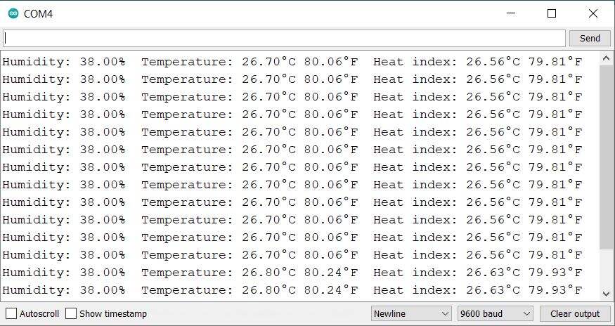
The Serial Monitor will display the temperature readings in degree Celcius as well as Fahrenheit. It will also show the value of Humidity and Heat Index.
Interfacing DHT11 Sensor with Arduino & LCD Display
Using the above code, we can display the temperature and humidity on Serial Monitor. Now lets modify the hardware as well as code to display the temperature and humidity value on 16×2 I2C LCD Display.
Hardware Connection
The hardware connection is very simple as shown in the schematic below.

Connect the SDA & SCL pin of LCD Display to Arduino A4 & A5 Pin respectively. Similarly connect the VCC & GND of LCD Display to 5V & GND of Arduino.

You may use the jumper wires again.
Source Code/Program
After LCD connection is done, you can move to the coding part of this project. We need to add LCD I2C Library to the Arduino library folder again
Here is a complete code for interfacing DHT11 Sensor with Arduino & 16×2 I2C LCD Display. Copy the following code and paste it on your Arduino IDE editor window.
|
1 2 3 4 5 6 7 8 9 10 11 12 13 14 15 16 17 18 19 20 21 22 23 24 25 26 27 28 29 30 31 32 33 34 35 36 37 38 39 40 41 42 43 44 45 46 47 48 49 50 51 52 53 54 55 56 57 58 59 60 61 62 63 |
#include <Wire.h> #include <LiquidCrystal_I2C.h> #include "DHT.h" LiquidCrystal_I2C lcd(0x27, 16, 2); #define DHTPIN 2 // Digital pin connected to the DHT sensor #define DHTTYPE DHT11 // DHT 11 DHT dht(DHTPIN, DHTTYPE); void setup() { Serial.begin(9600); lcd.init(); lcd.backlight(); dht.begin(); } void loop() { // Reading temperature or humidity takes about 250 milliseconds! // Sensor readings may also be up to 2 seconds 'old' (its a very slow sensor) float h = dht.readHumidity(); // Read temperature as Celsius (the default) float t = dht.readTemperature(); // Read temperature as Fahrenheit (isFahrenheit = true) float f = dht.readTemperature(true); // Check if any reads failed and exit early (to try again). if (isnan(h) || isnan(t) || isnan(f)) { Serial.println(F("Failed to read from DHT sensor!")); return; } // Compute heat index in Fahrenheit (the default) float hif = dht.computeHeatIndex(f, h); // Compute heat index in Celsius (isFahreheit = false) float hic = dht.computeHeatIndex(t, h, false); Serial.print(F("Humidity: ")); Serial.print(h); Serial.print(F("% Temperature: ")); Serial.print(t); Serial.print(F("°C ")); Serial.print(f); Serial.print(F("°F Heat index: ")); Serial.print(hic); Serial.print(F("°C ")); Serial.print(hif); Serial.println(F("°F")); lcd.setCursor(0, 0); lcd.print("Temp: "); lcd.print(t); lcd.print("*C"); lcd.setCursor(0, 1); lcd.print("Humi: "); lcd.print(h); lcd.print("%"); delay(2000); lcd.clear(); } |
Upload the code to your Arduino Board. After the code is uploaded, the LCD Display will show the value of Temperature and Humidity. The reading changes after every 2 seconds.

You may heat the sensor to observe the change in readings on the LCD Display.

")


