Close Menu
  • Articles
    • Learn Electronics
    • Product Review
    • Tech Articles
  • Electronics Circuits
    • 555 Timer Projects
    • Op-Amp Circuits
    • Power Electronics
  • Microcontrollers
    • Arduino Projects
    • STM32 Projects
    • AMB82-Mini IoT AI Camera
    • BLE Projects
  • IoT Projects
    • ESP8266 Projects
    • ESP32 Projects
    • ESP32 MicroPython
    • ESP32-CAM Projects
    • LoRa/LoRaWAN Projects
  • Raspberry Pi
    • Raspberry Pi Projects
    • Raspberry Pi Pico Projects
    • Raspberry Pi Pico W Projects
  • Electronics Calculator
Facebook X (Twitter) Instagram
  • About Us
  • Disclaimer
  • Privacy Policy
  • Contact Us
  • Advertise With Us
Facebook X (Twitter) Instagram Pinterest YouTube LinkedIn
How To Electronics
  • Articles
    • Learn Electronics
    • Product Review
    • Tech Articles
  • Electronics Circuits
    • 555 Timer Projects
    • Op-Amp Circuits
    • Power Electronics
  • Microcontrollers
    • Arduino Projects
    • STM32 Projects
    • AMB82-Mini IoT AI Camera
    • BLE Projects
  • IoT Projects
    • ESP8266 Projects
    • ESP32 Projects
    • ESP32 MicroPython
    • ESP32-CAM Projects
    • LoRa/LoRaWAN Projects
  • Raspberry Pi
    • Raspberry Pi Projects
    • Raspberry Pi Pico Projects
    • Raspberry Pi Pico W Projects
  • Electronics Calculator
How To Electronics
Home » Zero-Cross Detector Circuit using Transistor with waveform
Electronics Circuits

Zero-Cross Detector Circuit using Transistor with waveform

Mamtaz AlamBy Mamtaz AlamUpdated:February 2, 20251 Comment3 Mins Read
Share Facebook Twitter LinkedIn Telegram Reddit WhatsApp
Zero-Cross Detector Circuit using Transistor
Share
Facebook Twitter LinkedIn Pinterest Email Reddit Telegram WhatsApp

Zero-Cross Detector Circuit using Transistor

The figure below shows the circuit diagram of the Zero-Cross Detector Circuit using Transistor. The 230V AC mains is stepped down by transforme to deliver the secondary output of 6V, 500 mA. The transformer output is rectified by a full-wave bridge rectifier comprising diodes D1 through D4 and then regulated by IC 7805.

You can learn more about zero-cross detector here: Zero-Cross Detector Theory

Electrolytic capacitors C2= 470uF and ceramic disc C3=0.1 uF are used for bypassing the ripples present in the regulated 5V power supply. A capacitor above 10μF is connected across the output of the regulator IC, while diode D9 protects the regulator IC in case their input is short to ground. LED acts as the power-on indicator and resistor R1 limits the current through LED.

Zero-Cross Detector Circuit using Transistor


About the Circuit

The components required for the circuit are:
1. 230V AC Primary to 9V, 500 mA Secondary Transformer
2. D1-D8 1N4007 Diode
3. 7805 Voltage Regulator IC
4. Q1,Q2 – BC547 Transistor
5. LED
6. Electrolytic Capacitor- 1uF,25V & 470uF,16 V
7. Ceramic Disk – 1uF
8. Resistors – 1K, 4.7K, 470E, 330E, 1K

Assemble the circuit as seen in the circuit diagram or you can try in the Proteus for simulation.


Working of the Zero-Cross Detector Circuit

This regulated 5V is also used as biasing voltage for both transistors Q1 & Q2. A pulsating DC voltage is applied to the base of transistor Q1 through diode D5 and resistors R3 & R2.

When the pulsating voltage goes to zero, the collector of transistor Q1 goes high. This is used for detecting the pulse when the voltage is zero. Finally, the detected pulse from the collector of transistor Q2.

Zero-Cross Detector Circuit using Transistor
Figure: Output Terminal to DSO

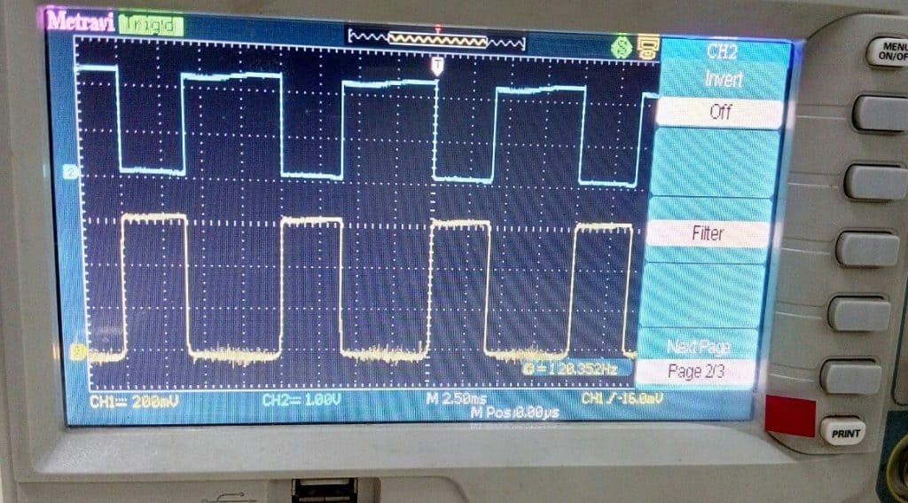
The complete operation can be well understood with the help of wave-forms in figure below:
1. The waveform before feeding into transistor Q1 is a fully rectified wave that is fed to its base.

  1. When the base voltage falls below transistor Q1 is switched off, pulling the output higher. This
    results in a very short positive pulse, which is available at the collector taken from the base of transistor Q2 as shown in the second waveform.

  2. As this positive pulse is inverted by transistor Q2, it produces one negative pulse of the same width
    at from collector of Q2 as shown in the third waveform.

    Fig: Waveform Output through different Terminal

Fig: Practical Output waveform from DSO
Share. Facebook Twitter Pinterest LinkedIn Tumblr Email Reddit Telegram WhatsApp
Previous ArticleInterfacing DHT11 Humdity & Temperature Sensor with Arduino & LCD
Next Article Dark/Light Detector using 555 Timer & LDR – Electronics Mini Project

Related Posts

Water Level Alert using Float Sensor & 555 Timer

Water Level Alert using Float Sensor & 555 Timer

2K
Adjustable Auto On Off Delay Timer Circuit Using 555 IC

555 Based Adjustable Auto On Off Delay Timer Circuit

Updated:February 14, 20252K

12V DC to 220V AC Inverter Circuit & PCB

Updated:February 2, 20251461K
DIY Smart Blind Stick using Op-Amp & IR Sensor

DIY Smart Blind Stick using Op-Amp & IR Sensor

Updated:February 2, 202515K
Square Wave Generator Circuit with Op Amp IC LM358

Square Wave Generator Circuit with Op Amp IC LM358

Updated:February 2, 202513K
Gas Leak Detection & Alarm using 555 Timer IC

Gas Leak Detection & Alarm using 555 Timer IC

Updated:February 2, 202525K
View 1 Comment

1 Comment

  1. Kali on December 28, 2021 10:24 PM

    Admin, there are a certain inaccuracies in the article. You wrote that:

    “The components required for the circuit are: … D1-D8 1N4007 Diode”. But on the schematic there is: D7 LED-GREEN diode (according to the description of D1-D8, these are the 1N4007 diodes).
    On the schematic there is D9 1N4007 diode but not exist in the required components.

    So it might be confusing to an electronics beginner 🙂

    Reply

CommentsCancel reply

Latest Posts

ESP32 Fingerprint Attendance System with Live Web Dashboard

June 14, 2026
IoT Based PM & Air Quality Monitoring System using ESP32

IoT Based PM & Air Quality Monitoring System using ESP32

June 14, 2026
DIY ESP32 MLX90640 IR Thermal Camera with Live Web Display

DIY ESP32 MLX90640 IR Thermal Camera with Live Web Display

May 10, 2026
IoT Activity Tracker with ESP32 & Accelerometer Gyroscope

IoT Activity Tracker with ESP32 & Accelerometer/Gyroscope

May 2, 2026
A Guide to Sourcing Obsolete ICs for Vintage Projects

Beyond AliExpress: A Guide to Sourcing Obsolete ICs for Vintage Projects

April 21, 2026

ESP32 IoT Vehicle Motion Analyzer with MPU6050 & LIS3MDL

April 27, 2026
Building a Smart Sensor Node with a BLE Microcontroller

Building a Smart Sensor Node with a BLE Microcontroller

February 26, 2026
High-Accuracy Pitch, Roll, Yaw with ESP32 & BNO08x IMU

High-Accuracy Pitch, Roll, Yaw with ESP32 & BNO08x IMU

April 27, 2026
Top Posts & Pages
  • IoT Based PM & Air Quality Monitoring System using ESP32
    IoT Based PM & Air Quality Monitoring System using ESP32
  • How to use LDR Sensor Module with Arduino
    How to use LDR Sensor Module with Arduino
  • 12V DC to 220V AC Inverter Circuit & PCB
    12V DC to 220V AC Inverter Circuit & PCB
  • Buck Converter: Basics, Working, Design & Application
    Buck Converter: Basics, Working, Design & Application
  • IoT AC Energy Meter with PZEM-004T & ESP32 WebServer
    IoT AC Energy Meter with PZEM-004T & ESP32 WebServer
  • How to use Modbus RTU with ESP32 to read Sensor Data
    How to use Modbus RTU with ESP32 to read Sensor Data
  • ECG Graph Monitoring with AD8232 ECG Sensor & Arduino
    ECG Graph Monitoring with AD8232 ECG Sensor & Arduino
  • Silicon Controlled Rectifier (SCR): Construction, Working & Applications
    Silicon Controlled Rectifier (SCR): Construction, Working & Applications
Categories
  • Arduino Projects (197)
  • Articles (60)
    • Learn Electronics (19)
    • Product Review (15)
    • Tech Articles (28)
  • Electronics Circuits (46)
    • 555 Timer Projects (21)
    • Op-Amp Circuits (7)
    • Power Electronics (13)
  • IoT Projects (205)
    • ESP32 MicroPython (7)
    • ESP32 Projects (82)
    • ESP32-CAM Projects (15)
    • ESP8266 Projects (76)
    • LoRa/LoRaWAN Projects (22)
  • Microcontrollers (38)
    • AMB82-Mini IoT AI Camera (4)
    • BLE Projects (18)
    • STM32 Projects (19)
  • Raspberry Pi (93)
    • Raspberry Pi Pico Projects (57)
    • Raspberry Pi Pico W Projects (12)
    • Raspberry Pi Projects (24)
Follow Us
  • Facebook
  • Twitter
  • Pinterest
  • Instagram
  • YouTube
About Us

“‘How to Electronics’ is a vibrant community for electronics enthusiasts and professionals. We deliver latest insights in areas such as Embedded Systems, Power Electronics, AI, IoT, and Robotics. Our goal is to stimulate innovation and provide practical solutions for students, organizations, and industries. Join us to transform learning into a joyful journey of discovery and innovation.

Copyright © How To Electronics. All rights reserved.
  • About Us
  • Disclaimer
  • Privacy Policy
  • Contact Us
  • Advertise With Us

Type above and press Enter to search. Press Esc to cancel.

Ad Blocker Enabled!
Ad Blocker Enabled!
Looks like you're using an ad blocker. Please allow ads on our site. We rely on advertising to help fund our site.