
Overview: GPS Vehicle Tracking System Arduino
In this project, we will learn about how to make GPS & GSM Based Vehicle Tracking System using Arduino. Most of the vehicle tracking system available in the market is too costly. So, I decided to make my own Tracking System. The vehicle tracking system will send you the location to your mobile phone along with the Google map coordinate. You can request the location at any time & view the location on Google Maps installed on your mobile phone.
This is a cheaper solution than a two-way GPS communication system where the communication is done in both ways with GPS satellites. This project uses only one GPS device and two-way communication is achieved using a GSM modem. The GSM modem with a 2G SIM card is used for communication between the device and mobile phone.
![]()
For this project, I have to select a proper low power GSM & GPS Module. So, I selected A9G GSM/GPRS/GPS Module. The device is very small and can fit anywhere & can be operated using a simple 3.7V Lithium-Ion Battery. The Board has a 32-bit ATSAMD21 controller from Atmel which can be programmed using Arduino IDE. You can also make this project using Neo-6M GPS Module & SIM 800/900 GSM Module with Arduino UNO Board. But this will make the device size large. We will discuss in detail about this Arduino GPS & GSM Based Vehicle Tracking System .
If you want to make a GPS tracker using a 4G internet connection instead of 2G, you can use SIM7600 4G LTE modem.
Bill of Materials
The Arduino based GPS Tracker Project can be done in 2 ways. The first way is using a single integrated device that has a combined GSM + GPS + Microcontroller. The second way is using the different available GSM & GPS Modules available in the market along with the Arduino Board.
I prefer the first method due to the compact size, low power consumption, and faster response. You can buy the combined module from the following link.
| S.N. | Components Name | Description | Quantity | Purchase Links |
|---|---|---|---|---|
| 1 | Maduino Zero Board | Maduino Zero GPRS/GPS A9G | 1 | https://makerfabs.com/maduino-zero-a9g.html |
| 2 | Battery | 3.7V 1000 mah Lithium-Ion Battery | 1 | Amazon | AliExpress |
If you want to make this GPS tracker using Arduino by the second method, you can buy the components separately and assemble on the breadboard or a PCB Board. All these components can be purchased from Amazon. The components purchase link is given below.
| S.N. | Components Name | Quantity | Purchase Links |
|---|---|---|---|
| 1 | Arduino UNO Board | 1 | Amazon | AliExpress |
| 2 | 16x2 LCD Display | 1 | Amazon | AliExpress |
| 3 | SIM800/900 GSM Module | 1 | Amazon | AliExpress |
| 4 | Neo-6M GPS Module | 1 | Amazon | AliExpress |
| 5 | Potentiometer 10K | 1 | Amazon | AliExpress |
| 6 | Connecting Jumper Wires | 10 | Amazon | AliExpress |
| 7 | Breadboard | 1 | Amazon | AliExpress |
Maduino Zero A9G GPRS/GPS Board
This is a low power A9G GSM+GPS+GPRS Module integrated with 32-bit Atmel’s SAMD21 Microcontroller. Its front side and backside look something like this.

The developer of the A9G GSM GPS Module is Ai-Thinker. The module can be programmed via micro USB Port and can be powered via 3.7V Lithium-Ion Battery. It has a switch to turn ON & OFF. The digital Input-Output pins are there which can be used to connect any other modules or sensors.
Arduino has an 8-bit controller but it has a 32 bit Atmel ATSAMD21G18 controller, which makes the device super fast. It has a voltage regulator IC to control the excess voltage. Similarly, there are two antennas, one is the GSM Antenna & another one the GPS Antenna. The signal problem is not seen in this module because of its best design. You can insert a micro sim here. Remember this is a 2G Modem only, so only 2G Sim can be used according to the frequency band. It also has a Micro-SD Port. You can also use an SD Card to save the data in text format.

The board doesn’t need any external DC Jack or higher power supply. It can be powered using a 3.7V, 100mah Lithium-Ion Battery. There are two battery ports in the module, one port is for the Battery charging and the other for the Battery power supply. Once the battery is connected, you can slide the switch to turn on the device. Two LEDs are there which indicated the status of the power.
This board is assembled and manufactured by Makerfabs, one of the best startup companies in China. You can directly purchase this board from the following link.
If you want to learn the basic interfacing and how to use AT Commands with the A9G Module, you can follow the following previous projects below. Apart from that, you can also learn about the GPS Tracker Project along with SMS Project & Cellular IoT Connectivity.
1. Basic A9G GPRS/GSM Module Arduino Tutorial: Check Here
2. GPS Tracker using Arduino & A9G: Check Here
3. Cellular IoT using Arduino & A9G: Check Here
Now let us move towards our main project, i.e. GPS+GSM Based Vehicle Tracking System using Arduino.
GPS+GSM Based Vehicle Tracking System using Arduino
You don’t need any external hardware part except connecting the Battery. All the documentation part is explained above. Now let us set up directly to the Arduino IDE setup part.
The Arduino IDE doesn’t have any pre-installed support for SAMD Board. So you need to add the Board first to the Arduino IDE. So, go to the board manager and search for Arduino Zero.
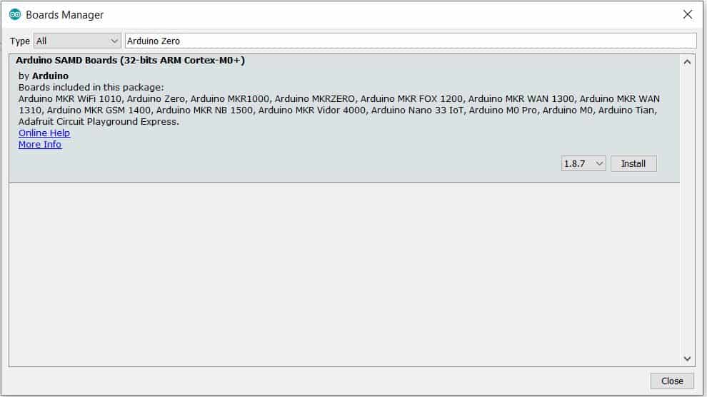
So here is the 32 bit ARM Cortex Board. You can install this board.
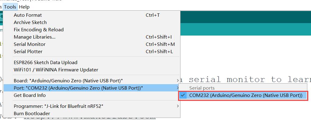
On the hardware part, connect the micro USB cable to the Maduino Zero Board. And also connect the other end to the computer USB port.
Now go to the tools, here you will find the Arduino SAMD Board. So from the list select the Arduino Zero Native USB Port. Also from the list select the com port.
Source Code/Program
So, you can see the program here. It is a little bit different compared to other GSM GPS Module & Arduino Boards. The AT Command AT+GPS=1 will turn on the GPS of the board. Similarly, AT+LOCATION =2 will retrieve the GPS Location as Latitude & Longitude Code.
Copy the complete code and upload it to the Arduino Zero Board.
|
1 2 3 4 5 6 7 8 9 10 11 12 13 14 15 16 17 18 19 20 21 22 23 24 25 26 27 28 29 30 31 32 33 34 35 36 37 38 39 40 41 42 43 44 45 46 47 48 49 50 51 52 53 54 55 56 57 58 59 60 61 62 63 64 65 66 67 68 69 70 71 72 73 74 75 76 77 78 79 80 81 82 83 84 85 86 87 88 89 90 91 92 93 94 95 96 97 98 99 100 101 102 103 104 105 106 107 108 109 110 111 112 113 114 115 116 117 118 119 120 121 122 123 124 125 126 127 128 129 130 131 132 133 134 135 136 137 138 139 140 141 142 143 144 145 146 147 148 149 150 151 152 153 154 155 156 157 158 159 160 161 162 163 164 165 166 167 168 169 170 171 172 173 174 175 176 177 178 179 180 181 182 183 184 185 186 187 188 189 190 191 192 193 194 195 196 197 198 199 200 201 202 203 204 |
#include<string.h> #define DEBUG true int PWR_KEY = 9; int RST_KEY = 6; int LOW_PWR_KEY = 5; String msg = String(""); int SmsContentFlag = 0; String mob; String loct; void setup() { pinMode(PWR_KEY, OUTPUT); pinMode(RST_KEY, OUTPUT); pinMode(LOW_PWR_KEY, OUTPUT); digitalWrite(RST_KEY, LOW); digitalWrite(LOW_PWR_KEY, HIGH); digitalWrite(PWR_KEY, HIGH); // String msg = String(""); // int SmsContentFlag = 0; SerialUSB.begin(115200); Serial1.begin(115200); //modulePowerOn(); delay(2000); SerialUSB.println("Checking Module..."); int i = 1; String res; while (i) { Serial1.println("AT"); while (Serial1.available() > 0) { if (Serial1.find("OK")) i = 0; } delay(500); } SerialUSB.println("Module Connected"); //GprsTextModeSMS(); SerialUSB.print("Text Mode: "); i = 1; while (i) { Serial1.println("AT+CMGF=1\r"); while (Serial1.available() > 0) { if (Serial1.find("OK")) i = 0; } delay(500); } SerialUSB.println("ON"); Serial1.println("AT+GPS=1"); SerialUSB.println("GPS Intializing..."); delay(5000); SerialUSB.println("GPS Initialized"); SerialUSB.flush(); i = 1; String str; while (i) { Serial1.println("AT+LOCATION=2"); delay(100); while (Serial1.available() <= 0); if (Serial1.find("AT+LOCATION=2")) { str = Serial1.readString(); //SerialUSB.println(str); i = 0; } delay(500); } loct = str.substring(4, 23); SerialUSB.print("Location: "); SerialUSB.println(loct); //while(1); SerialUSB.println("Send sms to get the location"); } void loop() { char SerialInByte; if (Serial1.available()) { //char SerialInByte; SerialInByte = (unsigned char)Serial1.read(); if ( SerialInByte == 13 ) //0x0D { ProcessGprsMsg(); } if ( SerialInByte == 10 ) { } else { //EN: store the current character in the message string buffer msg += String(SerialInByte); } } if (SmsContentFlag == 1) { int i; SerialUSB.println("Flag Cleared"); SerialUSB.print("Message: "); SerialUSB.println(msg); if (msg.indexOf("Location")) { SerialUSB.println("Message Received"); i = msg.indexOf("+91"); //SerialUSB.print("index: "); //SerialUSB.println(i); //SerialUSB.println(msg[i+1]); i = i + 3; for (int j = 0; j < 10; j++, i++) { mob += msg[i]; } SerialUSB.print("Mobile: "); SerialUSB.println(mob); String cmd = "AT+CMGS=\""; cmd += mob; cmd += "\""; cmd += "\r"; Serial1.println(cmd); delay(100); Serial1.print("Your Vehicle Current Location "); Serial1.print(loct); Serial1.print("\n"); Serial1.print("Check Map: \n"); Serial1.print(" https://www.google.com/maps/@"); Serial1.println(loct); Serial1.println((char)26); delay(1000); } ClearGprsMsg(); SmsContentFlag = 0; msg.remove(0); mob.remove(0); } delay(100); } // EN: Request Text Mode for SMS messaging void GprsTextModeSMS() { Serial1.println( "AT+CMGF=1" ); } void GprsReadSmsStore( String SmsStorePos ) { // Serial.print( "GprsReadSmsStore for storePos " ); // Serial.println( SmsStorePos ); Serial1.print( "AT+CMGR=" ); Serial1.println( SmsStorePos ); } // EN: Clear the GPRS shield message buffer void ClearGprsMsg() { msg = ""; } // EN: interpret the GPRS shield message and act appropiately void ProcessGprsMsg() { SerialUSB.println(""); // Serial.print( "GPRS Message: [" ); SerialUSB.print( msg ); // Serial.println( "]" ); if ( msg.indexOf( "Call Ready" ) >= 0 ) { SerialUSB.println( "*** GPRS Shield registered on Mobile Network ***" ); GprsTextModeSMS(); } //EN: unsolicited message received when getting a SMS message if ( msg.indexOf( "+CIEV" ) >= 0 ) { SerialUSB.println( "*** SMS Received ***" ); } //EN: SMS store readed through UART (result of GprsReadSmsStore request) if ( msg.indexOf( "+CMT:" ) >= 0 ) { // EN: Next message will contains the BODY of SMS SmsContentFlag = 1; // EN: Following lines are essentiel to not clear the flag! //ClearGprsMsg(); return; } // EN: +CMGR message just before indicate that the following GRPS Shield message // (this message) will contains the SMS body if ( SmsContentFlag == 1 ) { SerialUSB.println( "*** SMS MESSAGE CONTENT ***" ); SerialUSB.println( msg ); SerialUSB.println( "*** END OF SMS MESSAGE ***" ); //ProcessSms( msg ); } /*ClearGprsMsg(); //EN: Always clear the flag SmsContentFlag = 0; */ } |
Working of the Arduino GPS+GSM Vehicle Tracking
After uploading the code, open the Serial Monitor. The Serial Monitor will display the initialization message. If the location is fixed Serial Monitor will display the Latitude and Longitude. If the location is still not retrieved, the Serial Monitor will still display Checking Module.
![]()
Now you can send the SMS to get the Location. So, on your mobile phone open the messaging app and then enter the phone number of the SIM used in the Arduino Zero board. After that, type the word “Location”, and then simply send it.
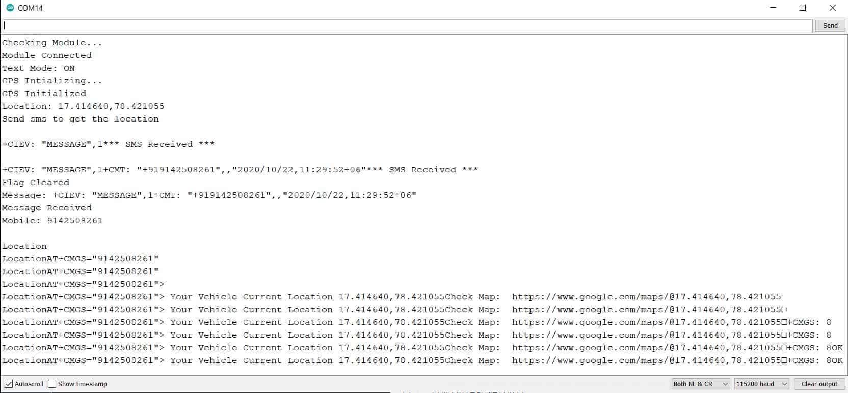
Within a while, the Serial Monitor will display the message received status and also tells about the date time, and mobile number. Similarly, you will receive an SMS on your mobile phone with the Latitude Longitude coordinate. Along with the coordinate, you will receive a link to google maps. You can click the link and open it either using google maps or using a Chrome browser.
![]()
So, you can see it’s pointing to the same location where I am right now. This is really a great project and can be implemented in your vehicles for a vehicle tracking project. It can be used for controlling the theft of the vehicle. Or it can be used in finding the location of someone who is using your vehicle.
Arduino based GPS Tracker Project using SIM800/900 & NEO-6M GPS Module
The same project can be done using Arduino UNO Board, SIM900 or SIM800 GSM Module, and also NEO-6M GPS Tracker Module. An extra LCD is also added to the circuit for displaying the status.
![]()
Source Code/Program
Here is the Source for the above circuit that is based on SIM800/900 GSM Module & NEO-6M GPS Module. This code a little bit smaller and requires a little modification like replacing a mobile phone number. Thus, GPS Based Vehicle Tracking System using Arduino can be easily tested.
|
1 2 3 4 5 6 7 8 9 10 11 12 13 14 15 16 17 18 19 20 21 22 23 24 25 26 27 28 29 30 31 32 33 34 35 36 37 38 39 40 41 42 43 44 45 46 47 48 49 50 51 52 53 54 55 56 57 58 59 60 61 62 63 64 65 66 67 68 69 70 71 72 73 74 75 76 77 78 79 80 81 82 83 84 85 86 87 88 89 90 91 92 93 94 95 96 97 98 99 100 101 102 103 104 105 106 107 108 109 110 111 112 113 114 115 116 117 118 119 120 121 122 123 124 125 126 127 128 129 130 131 132 133 134 135 136 137 138 139 140 141 142 143 144 145 146 147 148 149 150 151 152 153 154 155 156 157 158 159 160 161 162 163 164 165 166 167 168 169 170 171 172 173 174 175 176 177 178 |
#include <TinyGPS++.h> #include <SoftwareSerial.h> #include<LiquidCrystal.h> LiquidCrystal lcd(13, 12, 11, 10, 9, 8); static const int RXPin = 4, TXPin = 3; static const uint32_t GPSBaud = 9600; // The TinyGPS++ object TinyGPSPlus gps; int temp=0,i; // The serial connection to the GPS device SoftwareSerial ss(RXPin, TXPin); String stringVal = ""; void setup(){ Serial.begin(9600); ss.begin(GPSBaud); lcd.begin(16,2); pinMode(13,OUTPUT); digitalWrite(13,LOW); lcd.print("Vehicle Tracking"); lcd.setCursor(0,1); lcd.print(" System "); delay(2000); gsm_init(); lcd.clear(); Serial.println("AT+CNMI=2,2,0,0,0"); lcd.print("GPS Initializing"); lcd.setCursor(0,1); lcd.print(" No GPS Range "); delay(2000); lcd.clear(); lcd.print("GPS Range Found"); lcd.setCursor(0,1); lcd.print("GPS is Ready"); delay(2000); lcd.clear(); lcd.print("System Ready"); temp=0; } void loop() { serialEvent(); while(temp) { while (ss.available() > 0) { gps.encode(ss.read()); if (gps.location.isUpdated()) { temp=0; digitalWrite(13,HIGH); tracking(); } if(!temp) break; } } digitalWrite(13,LOW); } void serialEvent() { while(Serial.available()>0) { if(Serial.find("Track Vehicle")) { temp=1; break; } else { temp=0; } } } void gsm_init() { lcd.clear(); lcd.print("Finding Module.."); boolean at_flag=1; while(at_flag) { Serial.println("AT"); delay(1); while(Serial.available()>0) { if(Serial.find("OK")) at_flag=0; } delay(1000); } lcd.clear(); lcd.print("Module Connected.."); delay(1000); lcd.clear(); lcd.print("Disabling ECHO"); boolean echo_flag=1; while(echo_flag) { Serial.println("ATE0"); while(Serial.available()>0) { if(Serial.find("OK")) echo_flag=0; } delay(1000); } lcd.clear(); lcd.print("Echo OFF"); delay(1000); lcd.clear(); lcd.print("Finding Network.."); boolean net_flag=1; while(net_flag) { Serial.println("AT+CPIN?"); while(Serial.available()>0) { if(Serial.find("+CPIN: READY")) net_flag=0; } delay(1000); } lcd.clear(); lcd.print("Network Found.."); delay(1000); lcd.clear(); } void init_sms() { Serial.println("AT+CMGF=1"); delay(400); Serial.println("AT+CMGS=\"850xxxxxxx\""); // use your 10 digit cell no. here delay(400); } void send_data(String message) { Serial.print(message); delay(200); } void send_sms() { Serial.write(26); } void lcd_status() { lcd.clear(); lcd.print("Message Sent"); delay(2000); lcd.clear(); lcd.print("System Ready"); return; } void tracking() { init_sms(); send_data("Vehicle Tracking Alert:"); Serial.println(" "); send_data("Your Vehicle Current Location is:"); Serial.println(" "); Serial.print("Latitude: "); Serial.print(gps.location.lat(), 6); Serial.print("\n Longitude: "); Serial.println(gps.location.lng(), 6); // https://www.google.com/maps/@8.2630696,77.3022699,14z Serial.print("https://www.google.com/maps/@"); Serial.print(gps.location.lat(), 6); Serial.print(','); Serial.print(gps.location.lng(), 6); Serial.print(",14z"); send_sms(); delay(2000); lcd_status(); } |
Video Tutorial & Guide

You may refer to some previous GPS Tracker-based projects:
- Real Time GPS Tracker using ESP8266 & Blynk with Maps
- GPS Tracker using A9G GPRS/GPS Module & Arduino
- ESP32 GPS Tracker using L86 GPS Module & OLED Display
- LoRa Based Low Power GPS Tracker with Arduino & ESP8266

")


19 Comments
hi, i already buy the A9G same as yours…which line in coding do i need to put the mobile number to received the message?
thank you!
There is no need to put mobile number for 1st code
Need to know the location by sending an SMS to this device every time?
Or by clicking on the link which the device first sent, can we find out continuously where the device location is and where it is going by which road?
so for arduino project what i need to type in sms section like in your device you typed LOCATION. if i use your code do i need to write LOCATION ?
Hi I read your article about the GPS+GMS tracking system and I really liked it, I have a project to do It about making a wrist worn watch for the visually impaired and I did with my friend a module containing ultrasonic sensor that detect obstacles with a distance of 50 cm and I would like and appreciate it if you will help me add this GPS+GMS module tracking with my ultrasonic module please contact me
Hi i’m developing GPS+GSM tracking system using the source code you provided, i get the following output from serial monitor: Module Connected
Text Mode: ON
GPS Intializing…
GPS Initialized
Location:
Send sms to get the location
i tried to send an sms i dont get a location i’m not sure what can be a problem
Hi why you used potentiometer in arudino is it for lcd display?? Please answer
Yes for adjusting lcd contrast.
I’m using a Maduino V3.5 SIM808 module and uploaded the code.
Serial monitor shows 3 lines:
GPS Initilaized
Location:
Send SMS to get the loation
I sent an SMS but did not get a reply.
What am I doing wrong?
Do I need to initialize the GPS using AT+GPS=1 ?
Please help!
Hello sir …. i have a problem when making this project … hope you can guide and give some advise to me….. I using arduino uno , sim900 and gps neo6… When i open serial moniter and set baud rate to 9600 it show me “AT” again again and again… How can i solve this error? very appreciated to ur project sir .. THANKS >>>
hallo sir i got a problem when making this project using arduino uno and gsm 900a same like code given. but im still got AT command in serial monitor in loop.. As i know it is finding module. how to solve this please if somebody know let me know.. very2 appreciate if someone can help me finish my final year project
The lcd is displaying ‘Finding Network” for the second code. What does this mean and how do I fix this?
Thanks @Alex Newton for this great articles about GPS Tracking.
I have the Maduino Zero A9G GPRS/GPS Board, but I don’t want to use battery, only 12v from car battery (also when the car is off, configuring the board with a SLEEP to low battery usage).
There are any consideration about converting the 12v to the board required input voltage (3.4-4.2V).
Also, on car ignition the power voltage can up to 14v some moments (and down to 10v after that).
Thanks!
Lito.
irsyad I want to contact with you related to GPS And GSM
hey did you got the solution to above problem even i am facing same issue
hey did you find the solution to this problem i am facing same issue with sim800l
Hello sir …. i have a problem when making this project … hope you can guide and give some advise to me….. I using arduino nano , sim800L and gps neo6… When i open serial moniter and set baud rate to 9600 it show me “AT” again again and again… How can i solve this error? very appreciated to ur project sir .. THANKS >>>
If you find a solution, please contact me
I am also getting same error