

Overview: A9G GSM/GPRS+GPS Module with Arduino
In this project, we will learn about A9 or A9G Low Power GSM/GPRS+GPS Module with Arduino. We will go through the product details and learn about its specifications. We will then interface this Module with Arduino Zero, based on 32-bit Atmel’s SAMD21 microcontroller. We will then go through few of the AT Commands, get the GPS Location, Receive an SMS, connect to the Internet, etc.
The A9G GPS Tracker is an IoT (Internet of things) Solution-based product that integrates a micro Controller ATSAMD21G18, GRRS/GSM+GPS module A9G with best power management and storage. The A9G Module is best suited for real IoT projects such as smart-home, outdoor monitoring, long-distance monitoring, GPS Tracker, etc. The module can be operated using 3.7V Lithium Ion Battery as it requires 3.5~4.2V typical 4.0V supply. The power consumption of this module ranges between 1.03mA to 1.14mA depending upon the application.
If you are from the region where 2G connectivity is not available, then you can use SIM7600 4G LTE for IoT applications. Compared to A9G the SIM7600 has so many features and advnatages but is very expensive.
Bill of Materials
Following are the list of materials required for learning in details about this Module. All the components can easily be purchased and well documented.
| S.N. | Components Name | Quantity | Purchase Link |
|---|---|---|---|
| 1 | A9/A9G Module | 1 | Makerfabs |
| 2 | 2G Sim Card | 1 | - |
| 3 | OLED Display | 1 | Amazon | AliExpress |
| 4 | DHT11 Sensor | 1 | Amazon | AliExpress |
| 5 | 3.7V Battery | 1 | Amazon | AliExpress |
| 6 | Data Cable | 1 | Amazon | AliExpress |
A9G GPRS/GSM+GPS Module

The A9/A9G is a complete quad-band GSM/GPRS module that combines GPRS and GPS technologies and integrates it in a compact SMD package, saving customers time and money in developing GNSS applications. The A9G can be used in a wide range of IoT applications and is ideal for IoT applications for home automation, industrial wireless control, wearable electronics, wireless location sensing devices, wireless location system signals, and other IoT applications.
Features
– Complete quad-band GSM / GPRS module, 800/900/1800 /1900MHz
– SMD package for easy MP & testing
– Low power mode, average current 2mA or less
– support GPS, BD
– Supports digital audio and analog audio, supports HR, FR, EFR, AMR voice coding
– Support voice calls and SMS messages
– Embedded network service protocol stack
– Support standard GSM07.07,07.05AT command and Anxin expandable command set
– Support PBCCH
– Supports firmware upgrade via serial port
You can go through the A9G Datasheet, if you want to learn more about this module.
Maduino Zero A9G GPRS/GPS Board
The A9G Module needs a microcontroller interface for operation. Hence any microcontroller including Arduino can be used with it.

One of the best board i found while browsing through the internet is Maduino Zero Board. Maduino Zero A9G is an IoT (Internet of things) Solution based on the 32-bit Atmel’s SAMD21 MCU and GPRS/GSM GPS module A9G. It integrates a Microcontroller ATSAMD21G18, GRRS/GSM GPS module A9G. The ATSAMD21G18 is a low-power, high-performance Microchip’s ARM® Cortex®-M0+ based flash microcontroller ideal for a wide range of home automation, consumer, metering, and industrial applications.
The Maduino Zero A9G is based on the Arduino & users can program it with Arduino IDE, which is very easy especially suit for the none-programmers. With this board, it is easy to add text, SMS, and data to your project. It is good for your smart home project or GPS tracker and so on.
To learn more about this board and to buy this board follow this link below:
Powering the Board
The best part about this board is you can program the device directly through Micro-USB data cable. You can use a 3.7V Lithium-Ion Battery to power it up if you need a portable solution. While MicroUSB connected, the board will be powered by MicroUSB first, while micro USB removed, it will switch to battery automatically. The power consumption is lesser than 2mA, so the device battery can last very long, and hence it is an ideal solution compared to SIM800, SIM900 Modules.
At the back of this module, it has a Micro SIM Card Holder and Micro SD Card Holder. You can use any 2G SIM for IoT Project.
Features
– BAT Input Voltage: 3.4-4.2V
– ATSAMD21G18, 32-Bit ARM Cortex M0+
– Micro SIM connector
– Integrated Power Control System
– Support AT Command
– Quad-Band: 850/900/1800/1900Mz
– Support GPS
– Support GPRS data traffic, the maximum data rate, download 85.6Kbps, upload 42.8Kbps
– Support SMS Text Messaging
– Support USB Power Charge
– Support Micro SD Card
– Interface: I2C/SPI/UART/18GPIO
– Arduino Compatible
– Working Temperature: -40 – 85℃
– Default Baud Rate: 115200
– Size: 40mm55mm
Installing Board to the Arduino IDE
The Maduino Zero A9G GPRS/GSM+GPS Board doesn’t have pre-installed Board in the Arduino IDE. So, we need to install “Arduino Zero Board” from the Board Manager.
Open the Boards Manager From the top Arduino IDE menu, select Tools-> Board-> Boards Manager… to open the Boards Manager dialog box. Then install Arduino SAMD Boards(32-bits ARM Cortex-M0+).

Once, installation is completed, you can now select the Arduino Zero board as shown in the image below. To program this Board you need to connect MicroUSB Data Cable.

Preparing the Hardware
Now its time to prepare the Board before starting any project. Solder all the male headers and the female header pins to the Board.

- Plug a MicroSIM card.
- Plug a GPS Antenna to the designator which shows GPS.
- Plug a GSM Antenna to designator which shows GSM.
- Plug a Micro USB Cable to Maduino Zero A9/A9G.
- (Optional in v3.3)Plug a 3.7V lithium battery
Programming the Maduino A9G GSM/GPRS+GPS with Arduino IDE
Now let us program the Board. We will first do a basic level programming and using AT Commands we will retrieve some information.
Copy the following code and upload it to the Maduino A9G Board.
|
1 2 3 4 5 6 7 8 9 10 11 12 13 14 15 16 17 18 19 20 21 22 23 24 25 26 27 28 29 30 31 32 33 34 35 36 37 38 39 40 41 42 43 44 45 46 47 48 49 50 51 52 53 54 55 56 57 58 59 60 61 62 63 64 65 66 67 68 69 70 71 72 73 74 75 76 77 78 79 80 81 82 83 84 85 86 87 88 89 90 91 92 93 94 95 96 97 98 99 100 |
#include <stdio.h> #include <string.h> #define DEBUG true int PWR_KEY = 9; int RST_KEY = 6; int LOW_PWR_KEY = 5; bool ModuleState=false; void setup() { pinMode(PWR_KEY, OUTPUT); pinMode(RST_KEY, OUTPUT); pinMode(LOW_PWR_KEY, OUTPUT); digitalWrite(RST_KEY, LOW); digitalWrite(LOW_PWR_KEY, HIGH); digitalWrite(PWR_KEY, HIGH); Serial1.begin(115200); digitalWrite(PWR_KEY, LOW); delay(3000); digitalWrite(PWR_KEY, HIGH); delay(10000); SerialUSB.begin(115200); //while (!SerialUSB) { ; // wait for serial port to connect } ModuleState=moduleStateCheck(); if(ModuleState==false)//if it's off, turn on it. { digitalWrite(PWR_KEY, LOW); delay(3000); digitalWrite(PWR_KEY, HIGH); delay(10000); SerialUSB.println("Now turnning the A9/A9G on."); } //sendData("AT+CCID", 3000, DEBUG); //sendData("AT+CREG?", 3000, DEBUG); //sendData("AT+CGATT=1", 1000, DEBUG); //sendData("AT+CGACT=1,1", 1000, DEBUG); //sendData("AT+CGDCONT=1,\"IP\",\"CMNET\"", 1000, DEBUG); //sendData("AT+CIPSTART=\"TCP\",\"www.mirocast.com\",80", 2000, DEBUG); SerialUSB.println("Maduino A9/A9G Test Begin!"); } void loop() { while (Serial1.available() > 0) { SerialUSB.write(Serial1.read()); yield(); } while (SerialUSB.available() > 0) { Serial1.write(SerialUSB.read()); yield(); } } bool moduleStateCheck() { int i = 0; bool moduleState=false; for (i = 0; i < 5; i++) { String msg = String(""); msg = sendData("AT", 1000, DEBUG); if (msg.indexOf("OK") >= 0) { SerialUSB.println("A9/A9G Module had turned on."); moduleState=true; return moduleState; } delay(1000); } return moduleState; } String sendData(String command, const int timeout, boolean debug) { String response = ""; Serial1.println(command); long int time = millis(); while ((time + timeout) > millis()) { while (Serial1.available()) { char c = Serial1.read(); response += c; } } if (debug) { SerialUSB.print(response); } return response; } |
A9G GSM/GPRS+GPS Module AT Commands
Once the code is uploaded, open the Serial Monitor. Select “Both NL & CR”, and baud rate 115200, it will show the board begin to work.
You can type AT & send. You will receive OK as response.

If you want to get information about the CCID number you can send the following command.
|
1 |
AT+CCID |
If you want to report GSM/GPRS signal quality, you can send the following command.
|
1 |
AT+CSQ |
To turn ON/OFF the GPS, you can send the following command.
|
1 2 3 |
AT+GPS=1 //Turn ON GPS AT+GPS=0 //Turn OFF GPS |

The following AT Command is used to read NEMA information every 10 seconds.
|
1 |
AT+GPSRD=10 |

Note: To get this command working, first turn on the GPS using “AT+GPS=1” command.
To stop retrieving NEMA information every 10 seconds, you can use send the following command.
|
1 |
AT+GPSRD=0 |
To get the GPS information in terms of Latitude & Longitude, you can use send the following command.
|
1 |
AT+LOCATION=2 |

A9G SMS Function
Now let us test SMS Feature for A9G GSM/GPRS+GPS Module. For doing this we will take one example Project.
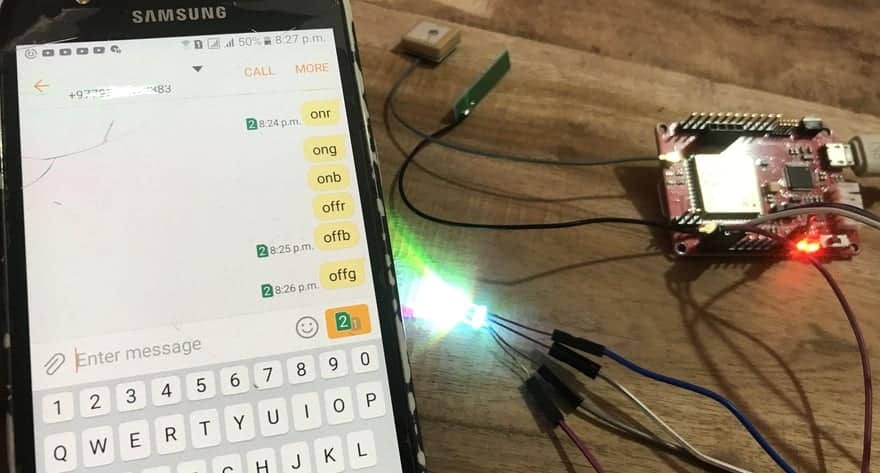
We will send SMS from our Smartphone and Turn ON/OFF the LED. To do that we will need an RGB LED and connect it to the Maduino A9G Board as shown below.

Connect the R, G, B Pins to the D2, D3, D4 of Maduino A9G Board. Connect the RGB LED VCC pin to 3.3V.
Now copy the following code and upload it to the Maduino Zero A9G Board.
|
1 2 3 4 5 6 7 8 9 10 11 12 13 14 15 16 17 18 19 20 21 22 23 24 25 26 27 28 29 30 31 32 33 34 35 36 37 38 39 40 41 42 43 44 45 46 47 48 49 50 51 52 53 54 55 56 57 58 59 60 61 62 63 64 65 66 67 68 69 70 71 72 73 74 75 76 77 78 79 80 81 82 83 84 85 86 87 88 89 90 91 92 93 94 95 96 97 98 99 100 101 102 103 104 105 106 107 108 109 110 111 112 113 114 115 116 117 118 119 120 121 122 123 124 125 126 127 128 129 130 131 132 133 134 135 136 137 138 139 140 141 142 143 144 145 146 147 148 149 150 151 152 153 154 155 156 157 158 159 160 161 162 163 164 165 166 167 168 169 170 171 172 173 174 175 176 177 178 179 180 181 182 183 184 185 186 187 188 189 190 191 192 193 194 195 196 197 198 199 200 201 202 203 204 205 |
#include<stdio.h> #include<string.h> #define DEBUG true int PWR_KEY=9; int RST_KEY=6; int LOW_PWR_KEY=5; int LED_R = 2; //D2 RED int LED_G = 3; //D3 GREEN int LED_B = 4; //D4 BLUE String msg = String(""); int SmsContentFlag = 0; void setup() { pinMode(PWR_KEY, OUTPUT); pinMode(RST_KEY, OUTPUT); pinMode(LOW_PWR_KEY, OUTPUT); digitalWrite(RST_KEY, LOW); digitalWrite(LOW_PWR_KEY, HIGH); digitalWrite(PWR_KEY, HIGH); pinMode(LED_R, OUTPUT); pinMode(LED_G, OUTPUT); pinMode(LED_B, OUTPUT); digitalWrite(LED_R, HIGH); digitalWrite(LED_G, HIGH); digitalWrite(LED_B, HIGH); // String msg = String(""); // int SmsContentFlag = 0; SerialUSB.begin(115200); while (!SerialUSB) { ; // wait for Arduino serial port to connect } Serial1.begin(115200); modulePowerOn(); GprsTextModeSMS(); } void loop() { char SerialInByte; if(SerialUSB.available()) { Serial1.print((unsigned char) SerialUSB.read()); } else if(Serial1.available()) { //char SerialInByte; SerialInByte = (unsigned char)Serial1.read(); if( SerialInByte == 13 )//0x0D { ProcessGprsMsg(); } if( SerialInByte == 10 ) { } else { //EN: store the current character in the message string buffer msg += String(SerialInByte); } } } void modulePowerOn() { int i=0; boolean result = false; digitalWrite(PWR_KEY, LOW); delay(3000); digitalWrite(PWR_KEY, HIGH); delay(15000); result = Serial1.find("OK"); if(result) SerialUSB.println( "Please send sms to control your device!" ); else { for(i=0;i<10;i++) { Serial1.println("AT"); delay(500); result = Serial1.find("OK"); if(result) { SerialUSB.println( "Please send sms to control your device!" ); return; } } } } void ProcessSms( String sms ) { SerialUSB.print( "ProcessSms for [" ); SerialUSB.print( sms ); SerialUSB.println( "]" ); if( sms.indexOf("onr") >= 0) { digitalWrite(LED_R, LOW); SerialUSB.println( "LED Red ON" ); //return; } if( sms.indexOf("ong") >= 0) { digitalWrite( LED_G, LOW); SerialUSB.println( "LED Green ON"); //return; } if( sms.indexOf("onb") >= 0 ) { digitalWrite(LED_B, LOW); SerialUSB.println( "LED Blue ON" ); //return; } if( sms.indexOf("offr") >= 0 ) { digitalWrite(LED_R,HIGH); SerialUSB.println( "LED Red OFF" ); //return; } if(sms.indexOf("offg") >= 0 ) { digitalWrite(LED_G, HIGH ); SerialUSB.println( "LED Green OFF" ); //return; } if( sms.indexOf("offb") >= 0 ) { digitalWrite(LED_B, HIGH ); SerialUSB.println( "LED Blue OFF" ); //return; } } // EN: Request Text Mode for SMS messaging void GprsTextModeSMS() { Serial1.println( "AT+CMGF=1" ); } void GprsReadSmsStore( String SmsStorePos ) { // Serial.print( "GprsReadSmsStore for storePos " ); // Serial.println( SmsStorePos ); Serial1.print( "AT+CMGR=" ); Serial1.println( SmsStorePos ); } // EN: Clear the GPRS shield message buffer void ClearGprsMsg() { msg = ""; } // EN: interpret the GPRS shield message and act appropiately void ProcessGprsMsg() { SerialUSB.println(""); // Serial.print( "GPRS Message: [" ); SerialUSB.print( msg ); // Serial.println( "]" ); if( msg.indexOf( "Call Ready" ) >= 0 ) { SerialUSB.println( "*** GPRS Shield registered on Mobile Network ***" ); GprsTextModeSMS(); } //EN: unsolicited message received when getting a SMS message if( msg.indexOf( "+CIEV" ) >= 0 ) { SerialUSB.println( "*** SMS Received ***" ); } //EN: SMS store readed through UART (result of GprsReadSmsStore request) if( msg.indexOf( "+CMT:" ) >= 0 ) { // EN: Next message will contains the BODY of SMS SmsContentFlag = 1; // EN: Following lines are essentiel to not clear the flag! ClearGprsMsg(); return; } // EN: +CMGR message just before indicate that the following GRPS Shield message // (this message) will contains the SMS body if( SmsContentFlag == 1 ) { SerialUSB.println( "*** SMS MESSAGE CONTENT ***" ); SerialUSB.println( msg ); SerialUSB.println( "*** END OF SMS MESSAGE ***" ); ProcessSms( msg ); } ClearGprsMsg(); //EN: Always clear the flag SmsContentFlag = 0; } |
Now the code is uploaded, so you can send the SMS to turn ON/OFF the LED. The message format according to the code is given below.
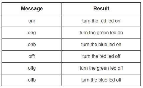
Now using any smartphone you can send ‘onr’ to turn the red led on, ‘offr’ to turn the red led off. Similarly, you can send ‘ong’ to turn the green led on, ‘offg’ to turn the green led off. The same thing applies for Blue LED as well.
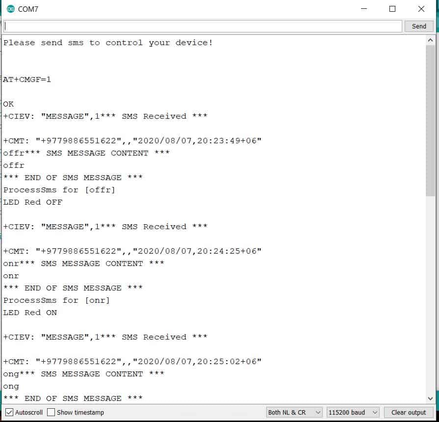
You can also open your Serial Monitor in Arduino IDE. You can monitor every happening displayed on Screen.
Well that’s all from the basic getting started tutorial for A9G GSM/GPRS+GPS Module with Arduino IDE.
Video Tutorial & Complete Guide

Visit this post to learn about GPS Tracker and GPRS Connectivity.
1. GPS Tracker using A9G GPRS/GPS Module & Arduino
2. Internet with A9G Low Power GPRS+GPS Module & Arduino

")


6 Comments
How to play an audio file during a call? The audio file is a .WAV file.
how are you able to make the AT+LOCATION=2 command to output the coordinates to the 12.345678, 12.345678 format? In my setup, it shows 1234.5678, 1234.5678.
Can you send an MMI Code with it?
eg:
1003*2#
Hi. Kindly guide me on how to send a pre-formatted sms by connecting a NO switch between two pins and triggering by pressing the switch. Any help will be appreciated.
‘Serial1’ was not declared in this scope
I am following the instruction from this tutorial: https://wiki.makerfabs.com/Maduino_Zero_A9G.html
However the command By using the official “AT+LOCATION=2” I always receive the following issue in the debug window:
+LOCATION: GPS NOT FIX NOW
+CME ERROR: 52
Can you please help to resolve this issue please ?