

Overview
In this article we will learn how to use SIM7600 GSM GPS 4G LTE Module with Arduino & use AT Commands to make receive call or send receive SMS or Internet Connection.
Earliier we use 2G GSM Module like SIM800/900 and also A9G GSM GPS module. As we know the 2G GSM/GPRS is in the stage of closing in most countries or regions like Australia & Canada. But there are indeed some projects that need remotely GSM wireless communication where WiFi is not available. In such regions, the project requires access to the Internet, such as remote environmental monitoring. Considering the investment/risk, for most cases, the LTE 4G is still a proper solution by now.
One of the most popular GSM GPS 4G LTE Module is SIM7600. The SIM7600 series is the LTE module that supports wireless communication modes of LTE. It also integrates multiple satellite high-accuracy positioning GNSS systems, with multiple built-in network protocols.
One of the readymade customized SIM7600 & Arduino board is designed by Makerfabs. This Maduino Zero 4G LTE module uses the SIMCOM7600(E/A)CAT4 module, to help Makers to achieve the 4G connection easily. Besides, this module can be a fully 4G access to your computer or Raspberry Pi, and also for call or SMS.
SIM7600 GSM GPS 4G LTE Module
The SIM7600 Series is Multi-Band LTE-TDD/LTE-FDD/HSPA+/TD-SCDMA and Dual-Band GSM/GPRS/EDGE module solution in a SMT type which supports LTE CAT4 up to 150Mbps for downlink data transfer.
It has strong extension capability with rich interfaces including UART, USB2.0, SPI, I2C, GPIO, etc. With abundant application capabilities like TCP/UDP/FTP/FTPS/HTTP/HTTPS/SMTP/POP3 and MMS, the module provides much flexibility and ease of integration for customers’ applications. To learn more about SIM7600 refer to SIM7600 Datasheet.
General features
- Quad-Band TDD-LTE B38/B39/B40/B41
- Tri-Band FDD-LTE B1/B3/B8
- Dual-Band TD-SCDMA B34/B39
- Dual-Band WCDMA/HSDPA/HSPA+ B1/B8
- GSM/GPRS/EDGE 900/1800 MHz
- Control Via AT Commands
- GNSS gpsOne Gen 8B; Standalone; Assisted, XTRA;
- Data Transfer: LTE CAT4 with Uplink up to 50Mbps & Downlink up to 150Mbps
- Interfaces: USB2.0, UART, SIM Card, SPI, I2C, GPIO, ADC, PCM, SDIO
Maduino Zero 4G LTE(SIM7600X) Board
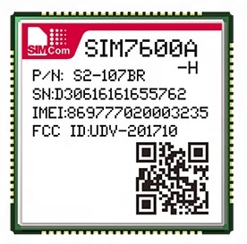
The Maduino Zero 4G LTE integrated two types of the 4G LTE CAT4 module SIM7600A-H or SIM7600E-H. The SIM7600A-H/SIM7600E-H is a complete multi-band LTE-FDD/LTE- TDD/HSPA+/UMTS/EDGE/GPRS/GSM module solution in LCC type. It supports LTE CAT4 up to 150Mbps for downlink and 50Mbps for uplink data transfer, much faster and popular than 2G/3G.

You can purchase this board from Maduino Zero 4G LTE(SIM7600X) as it is manufactured by Makerfabs.
Interface
Makerfabs Maduino Zero 4G LTE module is based on ATSAMD21G18A microcontroller, which is Arduino compatible. Hence you can use Arduino IDE to operate and program the SIM7600 Module. The front and back side of the board looks something like this.

On the front side you can connect a 3.7V Lithium-Ion Battery to the battery connector. The switch can be used to turn ON/OFF the module. There are two USB TypeC ports, one for microcontroller and the other for LTE. There are two pushbuttons used for MCU & LTE reset. The stat LED indicates the network connectivity status. You can connect 3 antennas to the board which are the main antenna, auxiliary antenna, and a GPS antenna. A 3.5mm Jack can be used to connect mic or earphones and an audio jack can be used for connecting speakers.
On the backside, there is a micro-sim slot for inserting a 4G SIM Card. There is a pair of SD Card slots, one for Microcontroller and the other for SIM7600.
Don’t plug or unplug the Antenna, SIM Cars, SD Card when the device is powered on. It may result in short-circuiting that may burn the IC down.
Features
- Supports dial-up, phone, SMS, TCP, UDP, DTMF, HTTP, FTP, and so on
- Dual USB Type C port
- Control Via AT Commands
- Board USB supply voltage range: 4.8~5.5V, 5.0V Typical
- Board Battery supply voltage range: 3.4~4.2V, 3.7V Typical
- 3GPP E-UTRA Release 11
- Onboard charger, up to 1A charge current
- Overcharge protection(OCP), 4.3V
- Over-discharge protection(ODP), 2.5V
- Power Manager, the board can be supplied by USB or battery.
- IPEX Antenna, GSM/UMTS/LTE main antenna. UMTS/LTE auxiliary antenna. GNSS antenna
- SMS support
- Audio support
- On boarder controller: ATSAMD21G18A
- Audio Codec: NAU8810
- Level Shifter: TXS0108E
- Windows and Raspberry Pi support
- Qualcomm MDM9x07 Chipset
Using SIM7600 GSM GPS 4G LTE with Arduino
Now let us see how we can use the SIM7600 GSM GPS 4G LTE with Arduino to use AT Commands for Call & SMS features.

- Plug the SIM card into the board.
- Plug the GPS antenna into the interface.
- Plug two 4G-GSM antennas into the main antenna interface and auxiliary one.
- Plug the headphone with the microphone.
- Plug the SD card into the SD card slot for SIM7600.
When powering the board and the SIM7600 module working, the onboard STA LED(blue) will turn on.
Setting up Arduino IDE
The ATSAMD21G18A board isn’t pre-installed in the Arduino IDE. So, we need to install “Arduino Zero Board” from the Board Manager.
Open the Boards Manager From the top Arduino IDE menu, select Tools-> Board-> Boards Manager… to open the Boards Manager dialog box. Then install Arduino SAMD Boards(32-bits ARM Cortex-M0+).

Once, installation is completed, you can now select the Arduino Zero board as shown in the image below. To program this Board you need to connect USB TypeC Data Cable.

Source Code/Program
Now open the Arduino IDE and paste the following sketches below.Verify the code and upload.
|
1 2 3 4 5 6 7 8 9 10 11 12 13 14 15 16 17 18 19 20 21 22 23 24 25 26 27 28 29 30 31 32 33 34 35 36 37 38 39 40 41 42 43 44 45 46 47 48 49 50 51 52 53 54 55 56 57 58 59 60 61 62 63 64 65 66 67 68 69 70 71 72 73 74 75 76 77 78 79 80 81 82 83 84 85 86 87 88 89 90 91 92 93 94 95 96 97 98 99 100 101 102 103 104 105 106 107 108 109 110 111 112 113 114 115 116 117 118 119 120 121 122 123 124 125 126 127 128 129 130 131 |
#include <stdio.h> #include <string.h> #define DEBUG true #define MODE_1A #define DTR_PIN 9 #define RI_PIN 8 #define LTE_PWRKEY_PIN 5 #define LTE_RESET_PIN 6 #define LTE_FLIGHT_PIN 7 String from_usb = ""; void setup() { SerialUSB.begin(115200); //while (!SerialUSB) { ; // wait for Arduino serial Monitor port to connect } delay(100); Serial1.begin(115200); //Serial1.begin(UART_BAUD, SERIAL_8N1, MODEM_RXD, MODEM_TXD); pinMode(LTE_RESET_PIN, OUTPUT); digitalWrite(LTE_RESET_PIN, LOW); pinMode(LTE_PWRKEY_PIN, OUTPUT); digitalWrite(LTE_RESET_PIN, LOW); delay(100); digitalWrite(LTE_PWRKEY_PIN, HIGH); delay(2000); digitalWrite(LTE_PWRKEY_PIN, LOW); pinMode(LTE_FLIGHT_PIN, OUTPUT); digitalWrite(LTE_FLIGHT_PIN, LOW); //Normal Mode // digitalWrite(LTE_FLIGHT_PIN, HIGH);//Flight Mode SerialUSB.println("Maduino Zero 4G Test Start!"); sendData("AT+CGMM", 3000, DEBUG); } void loop() { while (Serial1.available() > 0) { SerialUSB.write(Serial1.read()); yield(); } while (SerialUSB.available() > 0) { #ifdef MODE_1A int c = -1; c = SerialUSB.read(); if (c != '\n' && c != '\r') { from_usb += (char)c; } else { if (!from_usb.equals("")) { sendData(from_usb, 0, DEBUG); from_usb = ""; } } #else Serial1.write(SerialUSB.read()); yield(); #endif } } bool moduleStateCheck() { int i = 0; bool moduleState = false; for (i = 0; i < 5; i++) { String msg = String(""); msg = sendData("AT", 1000, DEBUG); if (msg.indexOf("OK") >= 0) { SerialUSB.println("SIM7600 Module had turned on."); moduleState = true; return moduleState; } delay(1000); } return moduleState; } String sendData(String command, const int timeout, boolean debug) { String response = ""; if (command.equals("1A") || command.equals("1a")) { SerialUSB.println(); SerialUSB.println("Get a 1A, input a 0x1A"); //Serial1.write(0x1A); Serial1.write(26); Serial1.println(); return ""; } else { Serial1.println(command); } long int time = millis(); while ((time + timeout) > millis()) { while (Serial1.available()) { char c = Serial1.read(); response += c; } } if (debug) { SerialUSB.print(response); } return response; } |
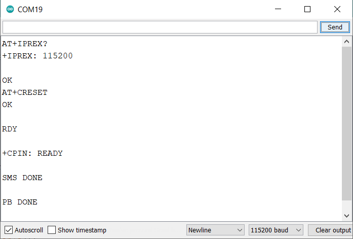
After uploading the code, open the serial monitor. You can now send the AT command to the board, and it will print the module response. There are some demos that show how to use the AT commands.
SIM7600 AT Commands Test
These are some basic functions to test AT Commands.
|
1 2 3 4 |
AT+CGMI // Request manufacturer identification AT+CGMM // Request model identification AT+CGSN // Request product serial number identification AT+CSUB // Request the module version and chip |

|
1 2 3 4 5 |
AT+CPIN? // Request the state of the SIM card AT+CICCID // Read ICCID from SIM card AT+CNUM // Request the subscriber number AT+CNMP? // Preferred mode selection AT+COPS? // Check the current network operator |

|
1 2 |
AT+IPREX? // Check local baud rate AT+CRESET // Reset the module |
Get the GNSS location
To get the GNSS Location from SIM7600, use the following AT Commands.
|
1 2 3 |
AT+CGPS=1 // Start GPS session AT+CGPSINFO // Get GPS fixed position information AT+CGPS=0 // Stop GPS session |

Send and receive SMS
We can send SMS using SIM7600 & Arduino. Is recommended to use other serial monitors not the Arduino IDE one to send the AT command for this demo.
|
1 2 3 |
AT+CSCA="XXXXXX" // Set the SMS service centre address AT+CMGF=1 // Select SMS message format AT+CMGS="xxxxxx" // Send message to "xxxxxx"(the receiver number). |
After sending the above AT commands, it will show “>” and then you can send your message. When you finish your message, you need to send “1A” with the hexadecimal for confirming or send “1B” with the hexadecimal for cancel. This is why it is recommended to use other serial monitor.

|
1 2 |
AT+CMGR=3 // Read message AT+CMGD=3 // Delete message |
Make a call
You can make or receive a call with SIM7600 using following AT Commands.
|
1 2 3 |
AT+CSDVC // Switch voice channel device AT+CSDVC=1 // 1-Handset, 3-Speaker phone AT+CLVL=2 // Set loudspeaker volume level to 2, the level range is 0 to 5 |

|
1 2 3 4 |
ATDxxxxx; // Call to xxxxx AT+CHUP // Hang up the call AT+CLIP=1 // Calling line identification presentation ATA // Call answer |
HTTP test
You can test the SIM7600 LTE HTTP request using following commands.
|
1 2 3 4 5 |
AT+HTTPINIT // Initialize and start the HTTP AT+HTTPPARA="URL","http://www.makerfabs.com" // Set the URL AT+HTTPACTION=0 // Connect the HTTP. (0-get, 1-post, 2-head) AT+HTTPHEAD // Read the response's header. AT+HTTPREAD=0,3 // Read the content (“3” means the number of the reading data) |

A detailed guide on how to make HTTP Post with SIM7600 is discussed on this article: Send Data with HTTP Post Method.
Test the SD card for SIM7600
When you plug an SD card into the SD card slot for SIM7600, You can use the following commands to check it.
|
1 2 3 4 |
AT+FSCD=D: // Select SD card directory as current directory AT+FSLS // List directories/files in current directory AT+CFTRANRX="D: TEST.txt",10 // Transfer a file to EFS AT+CFTRANTX="D: TEST.txt" // Transfer a file from EFS to host |
Surfing the Internet using SIM7600
The SIM7600 Arduino Modem can be a wireless networking device to support the PC or Raspberry PI surfing the internet. Use Type-C USB cable to connect the board(USB-LTE) and PC.

For surfing the internet you need to install the SIM7600 driver to the PC. The driver is available on resources.

Open Device Manager – > Other equipment – >“SimTech,Incorporated”- > Update the driver – > Browse my computer to find driver files – > Select a path for saving the driver file based on the system- >The installation is complete.
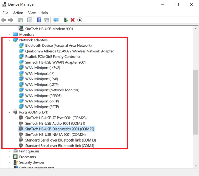
Install all the drivers that show as the yellow exclamation marks.
If the PC does not connect to the internet through this device, please open the serial monitor and send the AT command to start the networking.
|
1 |
AT$QCRMCALL=1,1 |
The network icon will then appear as a cellular network.

If have are still not able to connect to the internet, please use the PPP dial-up connection way to start networking. More info you can get from GitHub.
Video Tutorial & Guide


")


13 Comments
Hi , is it possible to use tinygsm library instead of sending all the AT command ?
The Tinygsm library might not work with this module. But you can give a try
Hi Admin!
I get error message “SerialUSB” was not declared in this scope.
It is ugrent that I fix this for work. Do you kindly have a solution?
Thank you!
SerialUSB command is not supported by Arduino UNO or ATmega328 based board. SerialUSB command is for ATSAMD based 32 bit controller.
Hi Admin
I used SIM7600GH and Andruino Uno R3 but when I open the Arduino IDE and paste the following sketches below.Verify the code, It’s indicated: ‘SerialUSB’ was not declared in this scope
So how to fix t, please?
Hi Tuan! I have the same issue, and it is ugent to fix it for work. Did you get a solution?
Thank you, have a good day!
No questions – this is just a brilliant web page. Congradualtions!
Am also getting the same error as shown in your call image.
No Carrier Found.
Where you able to fix it ?
Hi My GPS is showing no info just ””’
Very good post!
Let me ask you something…
You define a “1A” token from serial port and you answer to the SIMCOM Serial1.write(26);
Why ASCII 26, I guess It’s SUB ASCII simbol? shouldn’t it be “>” simbol?
Thanks!
You have to include this line of code on the top of the sketch:
#define SerialUSB Serial
Arduino always load Serial ports and some other stuff, you only have to access it through his new name!
Best!
Hi! Did you ever find a solution to this? I am getting empty GPS values as well.
AT+CMGS = “+2348023411675”
This is used to send SMS from the IDE monitor.
But how do you send this same statement as part of the Arduino code?