

Overview
In this article, we will learn the Interfacing of DS18B20 Temperature Sensor with Raspberry Pi Pico using MicroPython. Earlier we read the inbuilt temperature sensor data from Raspberry Pi Pico. But we will interface the external sensor like DS18B20 to the circuit.
The DS18B20 is a 1-wire programmable temperature sensor from Maxim integrated that requires only one data line for communication with a central microprocessor. Since the communication protocol is digital, hence you can use any digital pin of the RP2040 microcontroller.
The micropython code requires few DS18B20 libraries like onewire & ds18x20. In first example we will simply read the temperature value from DS18B20 & Raspberry Pi Pico in Thonny IDE Shell. In the second example, we will use a 0.96″ I2C OLED Display to display the temperature reading.
Bill of Materials
| S.N. | Components Name | Quantity | Purchase Links |
|---|---|---|---|
| 1 | Raspberry Pi Pico | 1 | Amazon | AliExpress |
| 2 | 0.96" I2C OLED Display | 1 | Amazon | AliExpress |
| 3 | DS1820 Temperature Sensor | 1 | Amazon | AliExpress |
| 4 | Resistor 4.7K | 1 | Amazon | AliExpress |
| 5 | Connecting Wires | 5 | Amazon | AliExpress |
| 6 | Breadboard | 1 | Amazon | AliExpress |
DS18B20 Waterproof Digital Temperature Sensor
This is a pre-wired and waterproofed version of the DS18B20 sensor. Handy for when you need to measure something far away, or in wet conditions. The Sensor can measure the temperature between -55 to 125°C (-67°F to +257°F). The cable is jacketed in PVC.
Because it is digital, there is no signal degradation even over long distances. These 1-wire digital temperature sensors are fairly precise, i.e ±0.5°C over much of the range. It can give up to 12 bits of precision from the onboard digital-to-analog converter. They work great with any microcontroller using a single digital pin.

The only downside is they use the Dallas 1-Wire protocol, which is somewhat complex and requires a bunch of code to parse out the communication. We toss in a 4.7k resistor, which is required as a pullup from the DATA to the VCC line when using the sensor.
To learn more about this sensor you can go through the DS18B20 Sensor Datasheet.
Interfacing DS18B20 Temperature Sensor with Raspberry Pi Pico
Now let us Interface DS18B20 Sensor with Raspberry Pi Pico RP2040 Board. The connection digram is given below.

The Sensor is powered by a 3.3V pin of Raspberry Pi Pico & GND is connected to GND. Similarly, the digital Pin is connected to GPIO22 of Pi Pico. The digital pin is pulled via 4.7K Resistor.

Library & Source Code
I used the thonny IDE that supports Micropython on the Raspberry Pi Pico. You need to import DS18B20 libraries. It requires OneWire and DS18X20 libraries. Download the libraries from following links.
DS18B20 MicroPython Library
OneWire MicroPython Library
Click on the file present inside the downloaded folder and then copy the contents of the entire file.
Click on the “New” button on the Thonny IDE to open a blank script and paste the following code.
|
1 2 3 4 5 6 7 8 9 10 11 12 13 14 15 16 17 18 19 20 21 22 23 |
import machine, onewire, ds18x20, time ds_pin = machine.Pin(22) ds_sensor = ds18x20.DS18X20(onewire.OneWire(ds_pin)) roms = ds_sensor.scan() print('Found DS devices: ', roms) while True: ds_sensor.convert_temp() time.sleep_ms(750) for rom in roms: print(rom) print(ds_sensor.read_temp(rom)) time.sleep(5) |
We used GP22 Pin of Raspberry Pi Pico for connecting the DS18B20 Sensor digital pin. Save the above file with .py extension. Then you can run the code.
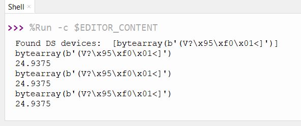
You can see output into Thonny Shell.
You must execute the convert_temp() function to initiate a temperature reading, then wait at least 750ms before reading the value. You use the read_temp function to return a value and we then pause for 5 seconds and run this again.
Temperature Display on OLED with DS18B20 & Raspberry Pi Pico
Now let us write an additional code to display the temperature value on OLED Screen. Here is the connection diagram. Connect the SDA & SCL Pin of OLED Display to PICO GP8 & GP9 Pin respectively. Connect the VCC & GND pin of OLED Display to 3.3V & GND Pin of Pico. You can use a breadboard to Assemble the entire circuit.

For this we need to write a OLED Driver code first as SSD1306 Driver is not available. The whole code is divided into 2 part:
1. ssd1306.py
2. Main.py
ssd1306.py
Open a New Tab & copy the following code. Save the file by the name SSD1306.py.
|
1 2 3 4 5 6 7 8 9 10 11 12 13 14 15 16 17 18 19 20 21 22 23 24 25 26 27 28 29 30 31 32 33 34 35 36 37 38 39 40 41 42 43 44 45 46 47 48 49 50 51 52 53 54 55 56 57 58 59 60 61 62 63 64 65 66 67 68 69 70 71 72 73 74 75 76 77 78 79 80 81 82 83 84 85 86 87 88 89 90 91 92 93 94 95 96 97 98 99 100 101 102 103 104 105 106 107 108 109 110 111 112 113 114 115 116 117 118 119 120 121 122 123 124 125 126 127 128 129 130 131 132 133 134 135 136 137 138 139 140 141 142 143 144 145 146 147 148 149 150 151 152 153 154 155 |
# MicroPython SSD1306 OLED driver, I2C and SPI interfaces from micropython import const import framebuf # register definitions SET_CONTRAST = const(0x81) SET_ENTIRE_ON = const(0xA4) SET_NORM_INV = const(0xA6) SET_DISP = const(0xAE) SET_MEM_ADDR = const(0x20) SET_COL_ADDR = const(0x21) SET_PAGE_ADDR = const(0x22) SET_DISP_START_LINE = const(0x40) SET_SEG_REMAP = const(0xA0) SET_MUX_RATIO = const(0xA8) SET_COM_OUT_DIR = const(0xC0) SET_DISP_OFFSET = const(0xD3) SET_COM_PIN_CFG = const(0xDA) SET_DISP_CLK_DIV = const(0xD5) SET_PRECHARGE = const(0xD9) SET_VCOM_DESEL = const(0xDB) SET_CHARGE_PUMP = const(0x8D) # Subclassing FrameBuffer provides support for graphics primitives # http://docs.micropython.org/en/latest/pyboard/library/framebuf.html class SSD1306(framebuf.FrameBuffer): def __init__(self, width, height, external_vcc): self.width = width self.height = height self.external_vcc = external_vcc self.pages = self.height // 8 self.buffer = bytearray(self.pages * self.width) super().__init__(self.buffer, self.width, self.height, framebuf.MONO_VLSB) self.init_display() def init_display(self): for cmd in ( SET_DISP | 0x00, # off # address setting SET_MEM_ADDR, 0x00, # horizontal # resolution and layout SET_DISP_START_LINE | 0x00, SET_SEG_REMAP | 0x01, # column addr 127 mapped to SEG0 SET_MUX_RATIO, self.height - 1, SET_COM_OUT_DIR | 0x08, # scan from COM[N] to COM0 SET_DISP_OFFSET, 0x00, SET_COM_PIN_CFG, 0x02 if self.width > 2 * self.height else 0x12, # timing and driving scheme SET_DISP_CLK_DIV, 0x80, SET_PRECHARGE, 0x22 if self.external_vcc else 0xF1, SET_VCOM_DESEL, 0x30, # 0.83*Vcc # display SET_CONTRAST, 0xFF, # maximum SET_ENTIRE_ON, # output follows RAM contents SET_NORM_INV, # not inverted # charge pump SET_CHARGE_PUMP, 0x10 if self.external_vcc else 0x14, SET_DISP | 0x01, ): # on self.write_cmd(cmd) self.fill(0) self.show() def poweroff(self): self.write_cmd(SET_DISP | 0x00) def poweron(self): self.write_cmd(SET_DISP | 0x01) def contrast(self, contrast): self.write_cmd(SET_CONTRAST) self.write_cmd(contrast) def invert(self, invert): self.write_cmd(SET_NORM_INV | (invert & 1)) def show(self): x0 = 0 x1 = self.width - 1 if self.width == 64: # displays with width of 64 pixels are shifted by 32 x0 += 32 x1 += 32 self.write_cmd(SET_COL_ADDR) self.write_cmd(x0) self.write_cmd(x1) self.write_cmd(SET_PAGE_ADDR) self.write_cmd(0) self.write_cmd(self.pages - 1) self.write_data(self.buffer) class SSD1306_I2C(SSD1306): def __init__(self, width, height, i2c, addr=0x3C, external_vcc=False): self.i2c = i2c self.addr = addr self.temp = bytearray(2) self.write_list = [b"\x40", None] # Co=0, D/C#=1 super().__init__(width, height, external_vcc) def write_cmd(self, cmd): self.temp[0] = 0x80 # Co=1, D/C#=0 self.temp[1] = cmd self.i2c.writeto(self.addr, self.temp) def write_data(self, buf): self.write_list[1] = buf self.i2c.writevto(self.addr, self.write_list) class SSD1306_SPI(SSD1306): def __init__(self, width, height, spi, dc, res, cs, external_vcc=False): self.rate = 10 * 1024 * 1024 dc.init(dc.OUT, value=0) res.init(res.OUT, value=0) cs.init(cs.OUT, value=1) self.spi = spi self.dc = dc self.res = res self.cs = cs import time self.res(1) time.sleep_ms(1) self.res(0) time.sleep_ms(10) self.res(1) super().__init__(width, height, external_vcc) def write_cmd(self, cmd): self.spi.init(baudrate=self.rate, polarity=0, phase=0) self.cs(1) self.dc(0) self.cs(0) self.spi.write(bytearray([cmd])) self.cs(1) def write_data(self, buf): self.spi.init(baudrate=self.rate, polarity=0, phase=0) self.cs(1) self.dc(1) self.cs(0) self.spi.write(buf) self.cs(1) |
main.py
After uploading the SSD1306.py, create a new tab again and copy the following code. Save this code as a name main.py.
|
1 2 3 4 5 6 7 8 9 10 11 12 13 14 15 16 17 18 19 20 21 22 23 24 25 26 27 28 29 30 31 32 33 34 35 36 37 38 39 40 41 42 43 44 45 46 47 48 49 50 |
# Display Image & text on I2C driven ssd1306 OLED display from machine import Pin, I2C from ssd1306 import SSD1306_I2C import machine import utime import onewire, ds18x20, time ds_pin = machine.Pin(22) ds_sensor = ds18x20.DS18X20(onewire.OneWire(ds_pin)) roms = ds_sensor.scan() print('Found DS devices: ', roms) WIDTH = 128 # oled display width HEIGHT = 64 # oled display height i2c = I2C(0, scl=Pin(9), sda=Pin(8), freq=200000) # Init I2C using pins GP8 & GP9 (default I2C0 pins) print("I2C Address : "+hex(i2c.scan()[0]).upper()) # Display device address print("I2C Configuration: "+str(i2c)) # Display I2C config oled = SSD1306_I2C(WIDTH, HEIGHT, i2c) # Init oled display while True: ds_sensor.convert_temp() time.sleep_ms(750) for rom in roms: print(rom) print(ds_sensor.read_temp(rom)) # Clear the oled display in case it has junk on it. oled.fill(0) # Add some text oled.text("Temperature: ",12,8) oled.text(str(round(ds_sensor.read_temp(rom),2)),30,30) oled.text("*C",75,30) utime.sleep(2) # Finally update the oled display so the image & text is displayed oled.show() |
Once you run the code, the OLED Display will start displaying the temperature value on OLED Screen.

This is how you can read the temperature data using DS18B20 Temperature Sensor MicroPython Code for Raspberry Pi Pico Board.


16 Comments
How can you use multiple ds18b20 sensors on a Pi Pico?
Thanks for tutorial.
I have my sensor wired as per your diagram, but didn’t work until I changed ds_pin to 17
Wire them in parallel, all three pins. The code will already read the temp from all the sensors found by the scan, the ids in the roms list. It prints them out and displays each one in turn if there are more than one.
Hi,
I followed your tutorial above but I can not get it to work. I have a Raspberry Pico W and also a DS18B20. I copied your code to Thonny but when running it I get a error message like this:
Traceback (most recent call last):
File “”, line 3, in
ImportError: can’t import name DS18X20
I looked for the ds18x20 library but can not find it anywhere.
Any suggestion how to solve this?
Regards,
Mats
Mats
Looks like they moved the onwire and ds18x20 libraries into micropython-lib.
onewire can be found here: https://github.com/micropython/micropython-lib/tree/master/micropython/drivers/bus/onewire
and
ds18x20 can be found here: https://github.com/micropython/micropython-lib/tree/master/micropython/drivers/sensor/ds18x20
Hi,
Thank’s for help. I found it now on the links you send me.
Regads,
Mats Bengtsson
Hi, I copied the code and installed the libraries (following the links given in your reply dd 30 Sept. However it doesn’t work. I get the following error messages:
Found DS devices: []
Traceback (most recent call last):
File “”, line 17, in
File “ds18x20.py”, line 20, in convert_temp
File “onewire.py”, line 23, in reset
OneWireError:
Any suggestions how to solve this?
Regards, Petra
Thats because the wiring diagram above is connected to pin number 22, not to GPIO 22.
The pin numbers are not equal to the GPIO numbering. GPIO 22 is located at pin number 29. So to get the code above to work, either change the pin number in the code to 17 as you did, or move the wire to pin 29.
I did connect another sensor. Just wire the red and black to 3.3V and GND as the first sensor, then the last wire to GP26 (physical pin 31).
Change the main.py like this:
import machine, onewire, ds18x20, time
ds_pin = machine.Pin(22)
ds2_pin = machine.Pin(26)
ds_sensor = ds18x20.DS18X20(onewire.OneWire(ds_pin))
ds2_sensor = ds18x20.DS18X20(onewire.OneWire(ds2_pin))
roms = ds_sensor.scan()
roms2 = ds2_sensor.scan()
print(‘Found DS devices: ‘, roms)
print(‘Found DS devices: ‘, roms2)
while True:
ds_sensor.convert_temp()
ds2_sensor.convert_temp()
time.sleep_ms(750)
for rom in roms:
for rom in roms2:
print(rom)
print(ds2_sensor.read_temp(rom))
time.sleep(5)
Hello, I am having a similar issue to others, I have copied the code and tried to run it but it resulted in this:
Found DS devices: []
Traceback (most recent call last):
File “”, line 13, in
File “ds18x20.py”, line 1, in convert_temp
File “onewire.py”, line 1, in reset
OneWireError:
I currently do not have a resistor but my wiring is:
Red > 3v3(out) (physical pin 36)
Black > Ground (physical pin 38)
Yellow > GP17 (Physical pin 22)
I have attempted to change the code to use pin 17 instead but I still get the same error, could it all be caused by the lack of resistor?
I agree you have to use the GPIO pin numbers in this case 17, not the physical ones, it then works fine
Bonjour,
Plus que novice. une ptite question: Comment augmenter la taille des caractère sur l’afficheur Oled.. D’avance MERCI
Yeah, amazing this hasn’t been corrected.
I’m having similar issues as others, my DS18 cables are white, red & yellow.
White connected to ground (physical pin 38)
Red connected to 3.3 (Physical pin 36)
Yellow connected to GP17 (Physical pin 22)
Resistor connected between red & yellow.
and it doesn’t detect any device:
import machine, onewire, ds18x20, time
ds_pin = machine.Pin(17)
ds_sensor = ds18x20.DS18X20(onewire.OneWire(ds_pin))
roms = ds_sensor.scan()
print(‘Found DS devices: ‘, roms)
Output:
Found DS devices: []
Appreciate your help.
As an alternative to the Raspberry Pi Pico, I can recommend trying ESP8266 boards, like NodeMCU or the D1 Mini v3.0.0. These can be found very cheap at sites like aliexpress. They can be used with the DS18B20 sensor, or if you dont need a waterproof sensor you can set it up with a BME280 sensor which monitors temperature, humidity and pressuse as well. There are lots of tutorials available. I followed a few of these and used D1 mini (clones) for a project to set up 8 wireless sensors (battery operated) together with a NodeMCU board as a server that upload all the sensor data to a google firebase database and allows me to monitor it via a web-app. The NodeMCU board also have a 8-channel solidstate relay board connected so I can use the relays for temperature control.
I had the same problem, change pin 22 to pin 17 on main.py and in the first code.