

Overview
In this guide, we will be Interfacing HMC5883L Triple Axis Digital Magnetometer with Arduino & OLED to our own Digital Compass. A digital compass using the HMC5883L magnetometer is possible as it’s a 3-axis magnetometer, which is often used to measure the strength and direction of the magnetic field. It can also be used as a compass to determine the Earth’s magnetic north.
The HCM5883L magnetometer will get the Compass reading and display the Magnetic Field of X, Y, Z axis in Microtesla (µT). Using this reading we can also calculate heading in degree. All these parameters can be displayed on 0.96″ OLED Display.
Bill of Materials
We need following components to work on this project.
| S.N. | Components | Quantity | Purchase Link |
|---|---|---|---|
| 1 | Arduino Nano | 1 | Amazon | AliExpress | SunFounder |
| 2 | HMC5883L Magnetometer | 1 | Amazon | AliExpress | SunFounder |
| 3 | 0.96" I2C OLED Display | 1 | Amazon | AliExpress | SunFounder |
| 4 | Jumper Wires | 10 | Amazon | AliExpress | SunFounder |
| 5 | Breadboard | 1 | Amazon | AliExpress | SunFounder |
What is a Magnetic Compass & Magnetometer?
A magnetic compass is a navigational instrument used to determine direction relative to Earth’s magnetic poles. It operates on the principle of magnetism, consisting of a small, lightweight magnet balanced on a nearly frictionless pivot point, often referred to as the compass needle.

The needle, which can rotate freely, aligns itself with Earth’s magnetic field, with its ends pointing towards magnetic north and magnetic south. This fundamental function allows users to establish their orientation in relation to the cardinal directions—north, south, east, and west.
A magnetometer is a passive instrument that measures changes in the Earth’s magnetic field, providing valuable insights for ocean exploration, including the survey of cultural heritage sites such as ship and aircraft wrecks, and the characterization of geological features on the seafloor.

Its operation is based on Earth’s core, which contains an outer liquid layer of magnetic iron and nickel. As Earth spins, the electric currents of these metals generate a magnetic field. This field’s strength varies across Earth’s surface and can be detected using a magnetometer.
HMC5883L 3-Axis Compass/Magnetometer
The HMC5883L is a digital compass designed by Honeywell. It’s a surface-mount, multi-chip module designed for low-field magnetic sensing. It’s particularly useful for providing directional information, which is why it’s often used in navigation and positioning systems.
The HMC5883L is built around anisotropic magnetoresistive (AMR) technology, which enables precision measurement of magnetic fields. It has three-axis sensors with fields ranging from ±1.3 to ±8.1 Gauss. This means it can measure magnetic fields on three different axes (X, Y, and Z), giving it the ability to sense the direction of the Earth’s magnetic field in three dimensions.
The HMC5883L comes with several built-in features that make it easy to integrate into various systems. These include a built-in ADC (Analog-to-Digital Converter) which provides 12-bit data output and a I2C serial bus interface. This interface is used for communicating with the device, allowing it to send data to a microcontroller or other processing unit.
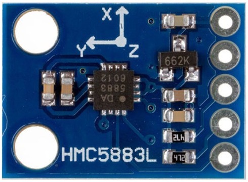
This HMC5883L Magnetometer Module consists of an HMC5883L Magnetometer IC, Voltage Regulator IC, resistors, and capacitors in an integrated circuit. It uses a voltage regulator IC XC6206P332MR (662K).
Refer to HMC5883L datsheets to learn more: Download HMC5883L Datasheet
Specifications of HMC5883L
- Operating Voltage: 3V to 6V DC
- Operating Current: 100-130 μA
- I2C interface
- 1-2 degree heading accuracy
- Integrated 12-bit ADC
- 160Hz max data rate
- Range of -8 to +8 Gauss
- Data Output Rate: 0.75, 1.5, 3, 7.5, 15 Hz
Pinout of HMC5883L
The HMC5883L module has five pins as shown in this image below:
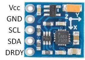
Here is a basic description of the typical pinout for an HMC5883L module.
- VCC: This is the power supply pin. It requires a DC voltage, typically 3V -6V.
- GND: This is the ground pin.
- SCL: This is the clock line for the I2C interface. It’s connected to the microcontroller’s I2C clock line.
- SDA: This is the data line for the I2C interface. It’s connected to the microcontroller’s I2C data line.
- DRDY: Data Ready. This pin goes low when new data is available. It’s optional and isn’t always used in basic applications.
Register Mapping & I2C Communication
| Register Address | Name | Access |
|---|---|---|
| 00 | Configuration Register A | Read/Write |
| 01 | Configuration Register B | Read/Write |
| 02 | Mode Register | Read/Write |
| 03 | Data Output X MSB Register | Read |
| 04 | Data Output X LSB Register | Read |
| 05 | Data Output Z MSB Register | Read |
| 06 | Data Output Z LSB Register | Read |
| 07 | Data Output Y MSB Register | Read |
| 08 | Data Output Y LSB Register | Read |
| 09 | Status Register | Read |
| 10 | Identification Register A | Read |
| 11 | Identification Register B | Read |
| 12 | Identification Register C | Read |
The HMC5883L magnetometer uses various internal registers to configure and receive data:
- Configuration Register A (0x00): Configures device operation, including output data rate and measurement configuration.
- Configuration Register B (0x01): Sets the device gain and sensitivity.
- Mode Register (0x02): Selects the operating mode, such as continuous measurement, single measurement, or idle mode.
- Data Output X Registers (0x03 and 0x04): Hold X-axis sensor readings.
- Data Output Y Registers (0x05 and 0x06): Hold Y-axis sensor readings.
- Data Output Z Registers (0x07 and 0x08): Hold Z-axis sensor readings.
- Status Register (0x09): Contains status flags about data output.
- Identification Registers (0x0A, 0x0B, 0x0C): Used to identify the device.
The HMC5883L employs the I2C communication protocol, functioning as a slave device. Its designated I2C device address is 0x1E. The corresponding addresses for its read and write operations are as follows:
- For write operations (SLA+W), the address is 0x3C.
- For read operations (SLA+R), the address is 0x3D.
Applications of HMC5883L
Some of the applications of HMC5883L Magnetometer in various fields are:
- Smart Devices: Auto-rotate and orientation features.
- GPS: Enhanced directional accuracy.
- Robotics: Improved navigation.
- Drones: Guidance and control.
- Gaming: Advanced motion tracking.
- AR/VR: Real-time orientation.
- Industrial Use: Satellite positioning, antenna tracking.
Interfacing HMC5883L Magnetometer with Arduino
Let us interface the HMC5883L Magnetometer with Arduino and read the magnetometer data for X, Y, Z axis along with the heading information.
Wiring Diagram
The connection diagram is very simple.

Connect the VCC & GND pin of magnetometer to 3.3V & GND Pin of Arduino. Similarly, connect the SDA & SCL pin of Magnetometer to A5 & A4 of Arduino.

I used Arduino Nano instead of Arduino UNO Board and connected HMC5883L with Arduino on breadboard using jumper wires.
Source Code/Program
Here is a basic source code for Arduino IDE that can read compass reading and display on Serial Monitor. Before compiling code, you need to install Adafruit HMC5883L library to the Arduino IDE.
Here is a complete code.
|
1 2 3 4 5 6 7 8 9 10 11 12 13 14 15 16 17 18 19 20 21 22 23 24 25 26 27 28 29 30 31 32 33 34 35 36 37 38 39 40 41 42 43 44 45 46 47 48 49 50 51 52 53 54 55 56 57 58 59 60 61 62 63 64 65 66 67 68 69 70 71 72 73 74 75 76 77 78 |
#include <Wire.h> #include <Adafruit_Sensor.h> #include <Adafruit_HMC5883_U.h> /* Assign a unique ID to this sensor at the same time */ Adafruit_HMC5883_Unified mag = Adafruit_HMC5883_Unified(12345); void displaySensorDetails(void) { sensor_t sensor; mag.getSensor(&sensor); Serial.println("------------------------------------"); Serial.print ("Sensor: "); Serial.println(sensor.name); Serial.print ("Driver Ver: "); Serial.println(sensor.version); Serial.print ("Unique ID: "); Serial.println(sensor.sensor_id); Serial.print ("Max Value: "); Serial.print(sensor.max_value); Serial.println(" uT"); Serial.print ("Min Value: "); Serial.print(sensor.min_value); Serial.println(" uT"); Serial.print ("Resolution: "); Serial.print(sensor.resolution); Serial.println(" uT"); Serial.println("------------------------------------"); Serial.println(""); delay(500); } void setup(void) { Serial.begin(9600); Serial.println("HMC5883 Magnetometer Test"); Serial.println(""); /* Initialise the sensor */ if(!mag.begin()) { /* There was a problem detecting the HMC5883 ... check your connections */ Serial.println("Ooops, no HMC5883 detected ... Check your wiring!"); while(1); } /* Display some basic information on this sensor */ displaySensorDetails(); } void loop(void) { /* Get a new sensor event */ sensors_event_t event; mag.getEvent(&event); /* Display the results (magnetic vector values are in micro-Tesla (uT)) */ Serial.print("X: "); Serial.print(event.magnetic.x); Serial.print(" "); Serial.print("Y: "); Serial.print(event.magnetic.y); Serial.print(" "); Serial.print("Z: "); Serial.print(event.magnetic.z); Serial.print(" ");Serial.println("uT"); // Hold the module so that Z is pointing 'up' and you can measure the heading with x&y // Calculate heading when the magnetometer is level, then correct for signs of axis. float heading = atan2(event.magnetic.y, event.magnetic.x); // Once you have your heading, you must then add your 'Declination Angle', which is the 'Error' of the magnetic field in your location. // Find yours here: http://www.magnetic-declination.com/ // Mine is: -13* 2' W, which is ~13 Degrees, or (which we need) 0.22 radians // If you cannot find your Declination, comment out these two lines, your compass will be slightly off. float declinationAngle = 0.22; heading += declinationAngle; // Correct for when signs are reversed. if(heading < 0) heading += 2*PI; // Check for wrap due to addition of declination. if(heading > 2*PI) heading -= 2*PI; // Convert radians to degrees for readability. float headingDegrees = heading * 180/M_PI; Serial.print("Heading (degrees): "); Serial.println(headingDegrees); delay(500); } |
Open the Serial Monitor once the code uploading is done.

The Serial Monitor will display the Magnetometer reading in X, Y, Z axis in micro-Tesla (uT) and also the heading angle in degrees.
Displaying HMC5883L Magnetometer Reading on OLED Display
Instead of displaying the HMC5883L Magnetometer Reading on Serial Monitor, lets display the reading on 0.96″ I2C OLED Display.
Wiring Diagram
The wiring diagram is very simple again.

Connect the OLED Display to I2C Pin of the Arduino.

Source Code/Program
Here is code to display the HMC5883L Digital Compass reading on OLED Display using the Arduino Nano Board. Before compiling code, you need to install Adafruit SSD1306 and Adafruit GFX libraries to the Arduino IDE.
Here is a complete code.
|
1 2 3 4 5 6 7 8 9 10 11 12 13 14 15 16 17 18 19 20 21 22 23 24 25 26 27 28 29 30 31 32 33 34 35 36 37 38 39 40 41 42 43 44 45 46 47 48 49 50 51 52 53 54 55 56 57 58 59 60 61 62 63 64 65 66 67 68 69 70 71 72 73 74 75 76 77 78 79 80 81 82 83 84 85 86 87 88 89 90 91 92 93 94 95 96 97 98 99 100 101 102 103 104 105 106 107 108 109 110 111 112 113 114 115 116 117 118 119 120 121 122 |
#include <Wire.h> #include <Adafruit_SSD1306.h> #include <Adafruit_Sensor.h> #include <Adafruit_HMC5883_U.h> #define SCREEN_WIDTH 128 // OLED display width, in pixels #define SCREEN_HEIGHT 64 // OLED display height, in pixels #define OLED_RESET -1 //Reset pin # (or -1 if sharing Arduino reset pin) #define SCREEN_ADDRESS 0x3C //See datasheet for Address Adafruit_SSD1306 display(SCREEN_WIDTH, SCREEN_HEIGHT, &Wire, OLED_RESET); /* Assign a unique ID to this sensor at the same time */ Adafruit_HMC5883_Unified mag = Adafruit_HMC5883_Unified(12345); void displaySensorDetails(void) { sensor_t sensor; mag.getSensor(&sensor); Serial.println("------------------------------------"); Serial.print ("Sensor: "); Serial.println(sensor.name); Serial.print ("Driver Ver: "); Serial.println(sensor.version); Serial.print ("Unique ID: "); Serial.println(sensor.sensor_id); Serial.print ("Max Value: "); Serial.print(sensor.max_value); Serial.println(" uT"); Serial.print ("Min Value: "); Serial.print(sensor.min_value); Serial.println(" uT"); Serial.print ("Resolution: "); Serial.print(sensor.resolution); Serial.println(" uT"); Serial.println("------------------------------------"); Serial.println(""); delay(500); } void setup(void) { Serial.begin(9600); Serial.println("HMC5883 Magnetometer Test"); Serial.println(""); /* Initialise the sensor */ if(!mag.begin()) { /* There was a problem detecting the HMC5883 ... check your connections */ Serial.println("Ooops, no HMC5883 detected ... Check your wiring!"); while(1); } /* Display some basic information on this sensor */ displaySensorDetails(); // SSD1306_SWITCHCAPVCC = generate display voltage from 3.3V internally if (!display.begin(SSD1306_SWITCHCAPVCC, SCREEN_ADDRESS)) { Serial.println(F("SSD1306 allocation failed")); for (;;); // Don't proceed, loop forever } display.clearDisplay(); display.display(); delay(500); } void loop(void) { /* Get a new sensor event */ sensors_event_t event; mag.getEvent(&event); /* Display the results (magnetic vector values are in micro-Tesla (uT)) */ Serial.print("X: "); Serial.print(event.magnetic.x); Serial.print(" "); Serial.print("Y: "); Serial.print(event.magnetic.y); Serial.print(" "); Serial.print("Z: "); Serial.print(event.magnetic.z); Serial.print(" "); Serial.println("uT"); display.clearDisplay(); display.setTextColor(SSD1306_WHITE); display.setCursor(25, 0); display.setTextSize(1); display.print("X: "); display.print(event.magnetic.x); display.print(" uT"); display.setCursor(25, 15); display.setTextSize(1); display.print("Y: "); display.print(event.magnetic.y); display.print(" uT"); display.setCursor(25, 30); display.setTextSize(1); display.print("Z: "); display.print(event.magnetic.z); display.print(" uT"); // Hold the module so that Z is pointing 'up' and you can measure the heading with x&y // Calculate heading when the magnetometer is level, then correct for signs of axis. float heading = atan2(event.magnetic.y, event.magnetic.x); float declinationAngle = 0.22; heading += declinationAngle; // Correct for when signs are reversed. if(heading < 0) heading += 2*PI; // Check for wrap due to addition of declination. if(heading > 2*PI) heading -= 2*PI; // Convert radians to degrees for readability. float headingDegrees = heading * 180/M_PI; Serial.print("Heading (degrees): "); Serial.println(headingDegrees); display.setCursor(0, 50); display.setTextSize(1); display.print("Heading: "); display.print(headingDegrees); display.print(" deg."); display.display(); delay(500); } |
After uploading the code, the OLED Display will show the reading of Magnetometer reading in X, Y, Z axis in micro-Tesla (uT) and also the heading angle in degrees.

You may rotate the Magnetometer or introduce some magnet near around HMC5883L to observe the change in the readings.
Making Digital Compass with HMC5883L Magnetometer & Arduino
By modifying the Arduino Code and using some OLED library functions we can make a Digital Compass with HMC5883L. Here is a complete code for this project.
|
1 2 3 4 5 6 7 8 9 10 11 12 13 14 15 16 17 18 19 20 21 22 23 24 25 26 27 28 29 30 31 32 33 34 35 36 37 38 39 40 41 42 43 44 45 46 47 48 49 50 51 52 53 54 55 56 57 58 59 60 61 62 63 64 65 66 67 68 69 70 71 72 73 74 75 76 77 78 79 80 81 82 83 84 85 86 87 88 89 90 91 92 93 94 95 96 97 98 99 100 101 102 103 104 105 106 107 |
#include <Wire.h> #include <Adafruit_SSD1306.h> #include <Adafruit_Sensor.h> #include <Adafruit_HMC5883_U.h> #define SCREEN_WIDTH 128 // OLED display width, in pixels #define SCREEN_HEIGHT 64 // OLED display height, in pixels #define OLED_RESET -1 // Reset pin # (or -1 if sharing Arduino reset pin) #define SCREEN_ADDRESS 0x3C // See datasheet for Address Adafruit_SSD1306 display(SCREEN_WIDTH, SCREEN_HEIGHT, &Wire, OLED_RESET); /* Assign a unique ID to this sensor at the same time */ Adafruit_HMC5883_Unified mag = Adafruit_HMC5883_Unified(12345); void setup(void) { Serial.begin(9600); Serial.println("HMC5883 Magnetometer Test"); /* Initialise the sensor */ if (!mag.begin()) { /* There was a problem detecting the HMC5883 ... check your connections */ Serial.println("Ooops, no HMC5883 detected ... Check your wiring!"); while (1); } // SSD1306_SWITCHCAPVCC = generate display voltage from 3.3V internally if (!display.begin(SSD1306_SWITCHCAPVCC, SCREEN_ADDRESS)) { Serial.println(F("SSD1306 allocation failed")); for (;;); // Don't proceed, loop forever } display.clearDisplay(); display.display(); delay(500); } void loop(void) { /* Get a new sensor event */ sensors_event_t event; mag.getEvent(&event); // Calculate heading when the magnetometer is level, then correct for signs of axis. float heading = atan2(event.magnetic.y, event.magnetic.x); float declinationAngle = 0.22; heading += declinationAngle; // Correct for when signs are reversed. if (heading < 0) heading += 2 * PI; // Check for wrap due to addition of declination. if (heading > 2 * PI) heading -= 2 * PI; // Convert radians to degrees for readability. float headingDegrees = heading * 180 / M_PI; display.clearDisplay(); display.setTextColor(SSD1306_WHITE); // Display angle in degrees display.setTextSize(2); display.setCursor(10, 10); display.print(headingDegrees, 0); display.print((char)247); // Display direction in bold letters display.setTextSize(3); display.setCursor(10, 40); if (headingDegrees >= 337.5 || headingDegrees < 22.5) display.print("N"); else if (headingDegrees >= 22.5 && headingDegrees < 67.5) display.print("NE"); else if (headingDegrees >= 67.5 && headingDegrees < 112.5) display.print("E"); else if (headingDegrees >= 112.5 && headingDegrees < 157.5) display.print("SE"); else if (headingDegrees >= 157.5 && headingDegrees < 202.5) display.print("S"); else if (headingDegrees >= 202.5 && headingDegrees < 247.5) display.print("SW"); else if (headingDegrees >= 247.5 && headingDegrees < 292.5) display.print("W"); else if (headingDegrees >= 292.5 && headingDegrees < 337.5) display.print("NW"); // Draw compass int centerX = SCREEN_WIDTH - 35; int centerY = SCREEN_HEIGHT / 2; int radius = min(centerX, centerY) - 3; // Increase the radius value for a larger circle display.drawCircle(centerX, centerY, radius, SSD1306_WHITE); display.fillCircle(centerX, centerY, 2, SSD1306_WHITE); // Added small dot at the center display.drawLine(centerX, centerY, centerX + radius * cos(heading - PI / 2), centerY + radius * sin(heading - PI / 2), SSD1306_WHITE); display.display(); delay(500); } |
After uploading the code, the Digital Compass is reading to use. The compass will show the arrow of the heading direction. The direction will also be displayed in degress along with the angle.

You may rotate the HMC5883L in different direction to observe the change in the reading of degress and direction.

The OLED can shows all the 8 direction like N, NE, E, SE, S, SW, W, NW.

You can rotate it to different different angles and observe the reading on OLED. The same project can also be implemented using MicroPython Code.
Conclusion
In conclusion, this guide has effectively shown how to interface an HMC5883L Triple Axis Digital Magnetometer with Arduino & OLED to create a fully functional digital compass. By utilizing the HMC5883L’s ability to measure the strength and direction of magnetic fields, we can precisely determine the Earth’s magnetic north. The compass readings are displayed in Microtesla (µT) for the X, Y, Z axes, and by processing these readings, we can calculate heading in degrees. All this information is seamlessly visualized on a 0.96″ OLED Display, enhancing the usability of this digital compass. By following this guide, anyone can develop a personalized, accurate, and highly informative digital compass.

")


2 Comments
How far can the sensor be from the Arduino? I need to make an antenna heading indicator but the antenna is 20 meters away from where the Arduino would be. Thanks for any help.
Hello, I would like to know what the code is but using a 1.5″ OLED screen. Thanks.