

Overview
In this project, we will build an IoT Based Water Level Control & Monitoring System with ESP8266 and Waterproof Ultrasonic Sensor. We can monitor the water level on Blynk Dashboard. Earlier we built Water level alert using 555 Timer IC.
An Internet of Things (IoT) water level control and monitoring system is a smart, automated solution to manage and maintain water levels in various applications such as tanks, reservoirs, and swimming pools. These systems use IoT devices, sensors, and cloud-based platforms to collect, process, and analyze data. This information is used to optimize water usage, prevent wastage, and provide real-time monitoring of water levels.
This project effectively addresses the issue of water wastage and maintains optimal water levels. Utilizing the ESP8266 WiFi Module as the primary controller, the system manages all electronic components and executes actions based on WiFi network connectivity. The JSN-SR04T waterproof ultrasonic sensor, positioned at the top of the tank, measures water levels. A 0.96″ I2C OLED screen displays these water levels for easy monitoring.
The device can operate in either manual or automatic mode, with a relay included in the circuit to control the water pump’s on/off state. Users can observe and manage the water level and mode control functions through the Blynk application, ensuring efficient water usage and conservation.
You may check some water level projects we build earlier:
Bill of Materials
We need the following components to build this IoT based Water Level Monitoring and Control project. You can purchase all the components from the given links.
| S.N. | Components | Quantity | Purchase Link |
|---|---|---|---|
| 1 | NodeMCU ESP8266 WiFi Module | 1 | Amazon | AliExpress |
| 2 | JSN-SR04T Ultrasonic Sensor | 1 | Amazon | AliExpress |
| 3 | 0.96" I2C OLED Display | 1 | Amazon | AliExpress |
| 4 | Hi-Link 220V AC to 5V DC Converter | 1 | Amazon | AliExpress |
| 5 | 5V Relay Module | 1 | Amazon | AliExpress |
| 6 | Push Button Switch | 2 | Amazon | AliExpress |
| 7 | AC Water Pump | 1 | Amazon | AliExpress |
| 8 | Pipes 2 meter or more | 1 | - |
| 9 | Zero PCB Board | 1 | Amazon | AliExpress |
The main controller used in this project is NodeMCU ESP8266 WiFi Module. For detecting the Water level of the tank, we can use Ultrasonic Sensor HC-SR04. But in this case, JSN-SR04T Waterproof Ultrasonic Sensor is a better choice.

The JSN-SR04T is an ultrasonic distance sensor which is a waterproof version of the popular HC-SR04 sensor. It is designed to work in harsher environmental conditions where water or moisture might be present. The module uses ultrasonic sound waves to determine the distance to an object by emitting a sound wave, and then measuring the time it takes for the echo to return.
For displaying Water level, we can use 0.96″ SSD1306 OLED Display. The SSD1306 0.96″ OLED Display is a popular and compact display module used in many DIY electronics projects. It is based on the SSD1306 driver chip, which is designed to drive monochrome OLED screens.
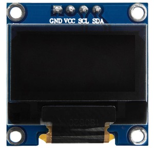
The display has a resolution of 128×64 pixels and provides a crisp, high-contrast image, making it suitable for various applications, such as displaying text, graphics, and icons. The module typically communicates with microcontrollers like Arduino, ESP8266, or Raspberry Pi using the I2C (Inter-Integrated Circuit) protocol.
For supplying power and controlling the relay, we used HLK-PM01 AC to 5V DC converter Module. The Hi-Link AC to 5V DC converter is a compact and efficient power supply module that converts AC mains voltage (typically 90V-264V AC) to a stable 5V DC output.
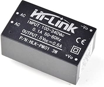
These modules are widely used in various electronics and IoT projects that require a 5V DC supply from the main power.
Circuit Design & Connection
The following is the IoT Based Water Level Control & Monitoring System circuit designed using Waterproof Ultrasonic Sensor & NodeMCU ESP8266 Board. I used Fritzing Software to design the Schematic.

The Waterproof Ultrasonic Sensor has 4 pins. The ECHO & TRIG Pin is connected to the D7 & D6 pin of ESP8266. It is powered by 5V from ESP8266. The OLED Display is an I2C Module, therefore its I2C Pins SDA & SCL is connected to D2 & D1 of NodeMCU ESP8266.
There are 3 push buttons used in this project. They are used as Mode Selection, Buzzer, and Relay operation. The Push Buttons are connected to D0, D3 & D4 pins respectively.
For the supply unit, HLK-PM01 AC to 5V DC converter Module can be used here. The 220V AC is fed as input and the 5V DC output is fed to the Vin pin of ESP8266. The Relay is controlled via Digital Pin D5 of ESP8266. To control the AC Motor Pump, the Relay plays a crucial role. When the Relay turns on, the Motor also turns on and when it goes off, the Motor turns off as well.
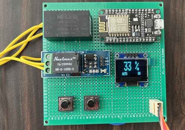
I used Zero PCB to assemble the circuit. All components fit perfectly on the board.

For my project I am only using 2 push buttons as I am not using the Buzzer on my board. You may use a buzzer in the PCB and activate via Push Button.
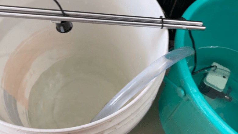
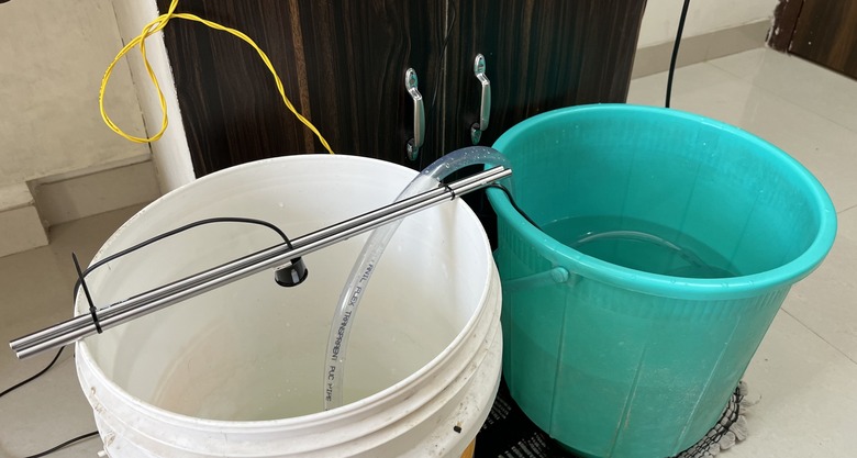
The Ultrasonic Sensor can be placed at the top of the tank and the motor can be placed inside the tank. Here in my project, I used two buckets. One bucket is like a tank and the other is a water source from where the motor pulls water.
You may use any AC Water Pump or just a 12V Output pump and connect at the output terminal of the Relay.
Setting up Blynk 2.0 Application
To control & monitor the Water Level, you need to create a Blynk project and set up a dashboard in the mobile or web application. Here’s how you can set up the dashboard:
Visit blynk.cloud and create a Blynk account on the Blynk website. Or you can simply sign in using the registered Email ID.
Click on +New Template. Then give any name to the Hardware. Choose the Hardware type as ESP8266 and the connection type as WiFi. The template is created successfully.
Now we need to add New Devices here.

Select the device from a template that you created earlier. Give any name and click on Create. A device authentication token is generated now. Copy this token as this will be used in the code.

Now go to the Web Dashboard. In the Web Dashboard, drag and drop 3 widgets as Gauge and 2 switches on the dashboard. Then set the Dashboard as per following Screenshots.


The Blynk Dashboard setup is successfully completed now.
Source Code/Program
The follow is the complete code for IoT ESP8266 Based Ultrasonic Water Level Monitoring System. The code is written in Arduino IDE.
There are few changes that you need to make before uploading this code to the Esp8266 Board.
From the following lines change the Blynk Authentication Token.
|
1 2 3 |
#define BLYNK_TEMPLATE_ID "***************" #define BLYNK_TEMPLATE_NAME "**********************" #define BLYNK_AUTH_TOKEN "*************************" |
Replace the WiFi SSID and Password from the following lines.
|
1 2 |
char ssid[] = "****************"; char pass[] = "**************"; |
After making these changes, you can now upload the code to the ESP8266 Board.
|
1 2 3 4 5 6 7 8 9 10 11 12 13 14 15 16 17 18 19 20 21 22 23 24 25 26 27 28 29 30 31 32 33 34 35 36 37 38 39 40 41 42 43 44 45 46 47 48 49 50 51 52 53 54 55 56 57 58 59 60 61 62 63 64 65 66 67 68 69 70 71 72 73 74 75 76 77 78 79 80 81 82 83 84 85 86 87 88 89 90 91 92 93 94 95 96 97 98 99 100 101 102 103 104 105 106 107 108 109 110 111 112 113 114 115 116 117 118 119 120 121 122 123 124 125 126 127 128 129 130 131 132 133 134 135 136 137 138 139 140 141 142 143 144 145 146 147 148 149 150 151 152 153 154 155 156 157 158 159 160 161 162 163 164 165 166 167 168 169 170 171 172 173 174 175 176 177 178 179 180 181 182 183 184 185 186 187 188 189 190 191 192 193 194 195 196 197 198 199 200 201 202 203 204 205 206 207 208 209 210 211 212 213 214 215 216 217 218 219 220 221 222 223 224 225 226 227 228 229 230 231 232 233 234 235 |
#include <Adafruit_SSD1306.h> #include <ESP8266WiFi.h> #include <BlynkSimpleEsp8266.h> #include <AceButton.h> #define BLYNK_TEMPLATE_ID "***************" #define BLYNK_TEMPLATE_NAME "**********************" #define BLYNK_AUTH_TOKEN "*************************" char ssid[] = "****************"; char pass[] = "**************"; int emptyTankDistance = 160; int fullTankDistance = 20; int triggerPer = 20; using namespace ace_button; #define TRIG 12 //D6 #define ECHO 13 //D7 #define Relay 14 //D5 #define BP1 2 //D0 #define BP2 13 //D3 #define BP3 15 //D4 #define V_B_1 V1 #define V_B_3 V3 #define V_B_4 V4 #define SCREEN_WIDTH 128 #define SCREEN_HEIGHT 32 #define OLED_RESET -1 Adafruit_SSD1306 display(SCREEN_WIDTH, SCREEN_HEIGHT, &Wire, OLED_RESET); float duration; float distance; int waterLevelPer; bool toggleRelay = false; bool modeFlag = true; String currMode; char auth[] = BLYNK_AUTH_TOKEN; ButtonConfig config1; AceButton button1(&config1); ButtonConfig config2; AceButton button2(&config2); ButtonConfig config3; AceButton button3(&config3); void handleEvent1(AceButton*, uint8_t, uint8_t); void handleEvent2(AceButton*, uint8_t, uint8_t); void handleEvent3(AceButton*, uint8_t, uint8_t); BlynkTimer timer; void checkBlynkStatus() { bool isconnected = Blynk.connected(); if (isconnected == false) { } if (isconnected == true) { } } BLYNK_WRITE(VPIN_BUTTON_3) { modeFlag = param.asInt(); if (!modeFlag && toggleRelay) { digitalWrite(Relay, LOW); toggleRelay = false; } currMode = modeFlag ? "AUTO" : "MANUAL"; } BLYNK_WRITE(VPIN_BUTTON_4) { if (!modeFlag) { toggleRelay = param.asInt(); digitalWrite(Relay, toggleRelay); } else { Blynk.virtualWrite(V_B_4, toggleRelay); } } BLYNK_CONNECTED() { Blynk.syncVirtual(V_B_1); Blynk.virtualWrite(V_B_3, modeFlag); Blynk.virtualWrite(V_B_4, toggleRelay); } void displayData() { display.clearDisplay(); display.setTextSize(3); display.setCursor(30, 0); display.print(waterLevelPer); display.print(" "); display.print("%"); display.setTextSize(1); display.setCursor(20, 25); display.print(currMode); display.setCursor(95, 25); display.print(toggleRelay ? "ON" : "OFF"); display.display(); } void measureDistance() { digitalWrite(TRIG, LOW); delayMicroseconds(2); digitalWrite(TRIG, HIGH); delayMicroseconds(20); digitalWrite(TRIG, LOW); duration = pulseIn(ECHO, HIGH); distance = ((duration / 2) * 0.343) / 10; if (distance > (fullTankDistance - 15) && distance < emptyTankDistance) { waterLevelPer = map((int)distance, emptyTankDistance, fullTankDistance, 0, 100); Blynk.virtualWrite(V_B_1, waterLevelPer); if (waterLevelPer < triggerPer) { if (modeFlag) { if (!toggleRelay) { digitalWrite(Relay, HIGH); toggleRelay = true; Blynk.virtualWrite(V_B_4, toggleRelay); } } } if (distance < fullTankDistance) { if (modeFlag) { if (toggleRelay) { digitalWrite(Relay, LOW); toggleRelay = false; Blynk.virtualWrite(V_B_4, toggleRelay); } } } } displayData(); delay(100); } void setup() { Serial.begin(9600); pinMode(ECHO, INPUT); pinMode(TRIG, OUTPUT); pinMode(Relay, OUTPUT); pinMode(BP1, INPUT_PULLUP); pinMode(BP2, INPUT_PULLUP); pinMode(BP3, INPUT_PULLUP); digitalWrite(Relay, HIGH); config1.setEventHandler(button1Handler); config2.setEventHandler(button2Handler); config3.setEventHandler(button3Handler); button1.init(BP1); button2.init(BP2); button3.init(BP3); currMode = modeFlag ? "AUTO" : "MANUAL"; if (!display.begin(SSD1306_SWITCHCAPVCC, 0x3C)) { Serial.println(F("SSD1306 allocation failed")); for (;;) ; } delay(1000); display.setTextSize(1); display.setTextColor(WHITE); display.clearDisplay(); WiFi.begin(ssid, pass); timer.setInterval(2000L, checkBlynkStatus); timer.setInterval(1000L, measureDistance); Blynk.config(auth); delay(1000); Blynk.virtualWrite(V_B_3, modeFlag); Blynk.virtualWrite(V_B_4, toggleRelay); delay(500); } void loop() { Blynk.run(); timer.run(); button1.check(); button3.check(); if (!modeFlag) { button2.check(); } } void button1Handler(AceButton* button, uint8_t eventType, uint8_t buttonState) { Serial.println("EVENT1"); switch (eventType) { case AceButton::kEventReleased: if (modeFlag && toggleRelay) { digitalWrite(Relay, LOW); toggleRelay = false; } modeFlag = !modeFlag; currMode = modeFlag ? "AUTO" : "MANUAL"; Blynk.virtualWrite(V_B_3, modeFlag); break; } } void button2Handler(AceButton* button, uint8_t eventType, uint8_t buttonState) { Serial.println("EVENT2"); switch (eventType) { case AceButton::kEventReleased: if (toggleRelay) { digitalWrite(Relay, LOW); toggleRelay = false; } else { digitalWrite(Relay, HIGH); toggleRelay = true; } Blynk.virtualWrite(V_B_4, toggleRelay); delay(1000); break; } } void button3Handler(AceButton* button, uint8_t eventType, uint8_t buttonState) { Serial.println("EVENT3"); switch (eventType) { case AceButton::kEventReleased: break; } } |
Testing & Demo
After uploading the code, you may start testing the project. Pu the device at the appropriate location and power it using the 220V AC Supply.
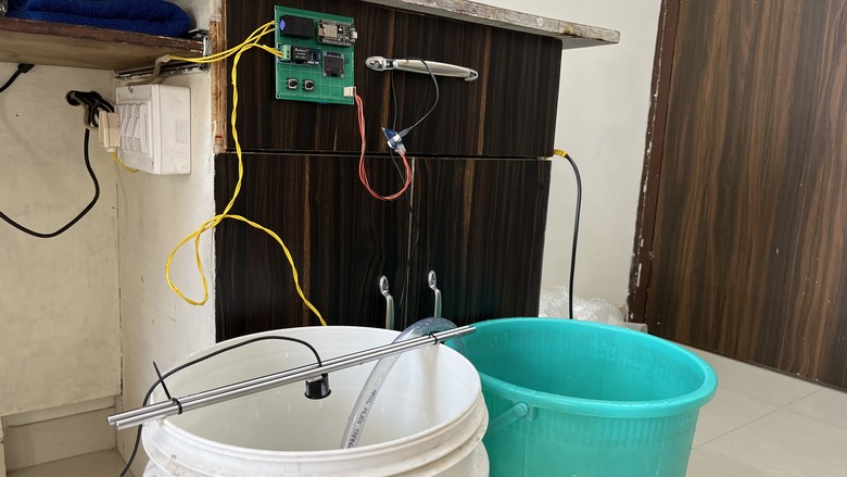
Submerge the motor in the Water source and put the Ultrasonic Sensor on the top of the tank. You may use Bucket for this propose.
The ESP8266 will connect to the WiFi Network. The OLED will display the Water level based on the level of Water available in the tank.

The Water level will change from 0-100% based on the level of water.
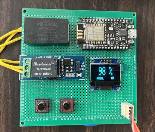
When the Water level reaches almost full, the tank will display 100% and motor will turn off.
The same thing can be observed online on Blynk Application. You can monitor the Water level of tank from any part of the world.
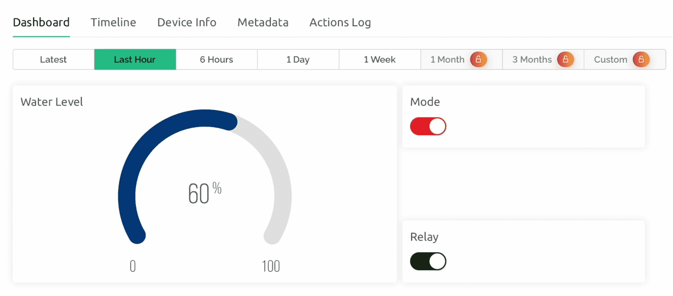
The Auto Mode and the Manual Mode can be selected from the Blynk Dashboard. You can force the Relay to turn on/off as well from the Dashboard. When manual mode button is pressed the Relay will turn on the motor despite whatever the water level is.
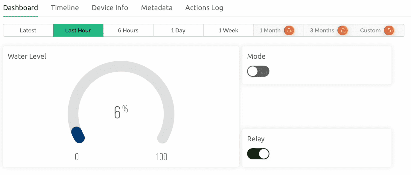
The Blynk Dashboard is available for both desktop and Mobile App. Everytime it shows Water Level in Gague and also allows the option to turn on the Relay from Dashboard and also by using Push Button on PCB. The Auto and Manual mode can be selected the same way.
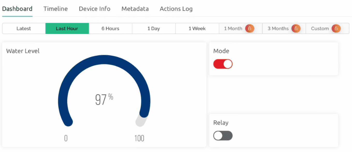
You can also configure the Blynk Dashboard to show the notification when the water level drops down certain level. The level can assigned in the code. The default is 20%.
Video Tutorial & Guide

 & Live Dashboard")


4 Comments
Thanks (:
What software do you use to make schematic drawings
you did not mention how to create DataStream for Switch’s and gauge.
Can you modifie this project
1 use lcd display
raj kumar 9815434100