

Overview
In this guide we will make a Voltage Doubler Circuit using 555 Timer IC. A voltage doubler is a type of circuit designed to produce an output voltage that is twice the input voltage. For example, when provided with a 3.3V input, the output will be 6.6V.
Earlier we build 12 to 24V Voltage Doubler Circuit using transformer and some capacitors. Although transformers are commonly used for voltage step-up or step-down, they may not always be suitable due to their size and expense. In such situations, a convenient, efficient, and cost-effective alternative is to use a 555-timer IC to achieve voltage doubling.
A voltage doubler circuit utilizing a 555 timer IC is an effective way to generate an output voltage that is double the input voltage. The 555 timer IC is a versatile and widely-used integrated circuit, which can be employed in this application to achieve voltage doubling without the need for bulky and costly transformers. Below is a basic outline of how to create a voltage doubler circuit using a 555 timer IC.
Components Required
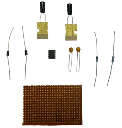
- 555 Timer IC
- 1N4007 Diode -2
- Resistors 10K
- Resistor 33K
- Capacitor 22uF – 2
- Capacitor 0.01uF – 2
- 3V-12V Battery
Voltage Doubler Circuit using 555 Timer IC
Here is a simple schematic of a Voltage Doubler Circuit designed using 555 Timer IC, some active passive components like Diodes, resistors, capacitors, etc.

We have set up the 555 Timer IC in Astable multivibrator mode to produce a square wave with an approximate frequency of 2 kHz. The frequency is determined by the values of resistors R1 and R2, as well as capacitor C1.
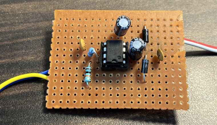
You may assemble the circuit on a breadboard or on a Zero PCB.
Working of the Voltage Doubler Circuit
The working of a voltage doubler circuit using a 555 timer IC can be understood by breaking it down into two main parts: the 555 timer IC in astable mode and the voltage doubler section.
- 555 Timer IC in Astable Mode:
In astable mode, the 555 timer IC generates a continuous square wave output with a specific frequency and duty cycle. The frequency and duty cycle are determined by the resistors R1 and R2 and capacitor C1 connected to pins 2, 6, and 7 of the IC.
When power is applied, the capacitor C1 starts charging through resistors R1 and R2. As the voltage across C1 increases, it reaches a threshold value (2/3 of the supply voltage) recognized by the internal comparator of the 555 timer IC. At this point, the output at pin 3 goes LOW, and the capacitor begins to discharge through resistor R2. When the voltage across C1 falls below another threshold value (1/3 of the supply voltage), the output at pin 3 goes HIGH again, and the charging cycle restarts. This process repeats indefinitely, producing a square wave output.
- Voltage Doubler Section:
The voltage doubler section consists of two diodes (D1 and D2) and two capacitors (C2 and C3). The square wave output from the 555 timer IC is used to charge and discharge these capacitors in a specific sequence, effectively doubling the voltage across capacitor C3.
During the positive half-cycle of the square wave output, diode D1 conducts, charging capacitor C2 to the input voltage level (minus the diode’s forward voltage drop). Diode D2 is reverse-biased during this time, preventing current flow through it. As a result, capacitor C3 does not charge during the positive half-cycle.
During the negative half-cycle of the square wave output, diode D1 becomes reverse-biased, and diode D2 conducts. Capacitor C2 discharges its stored voltage into capacitor C3, effectively charging C3 to twice the voltage level of C2 (minus the voltage drop across D2).
The output voltage, which is double the input voltage, can be obtained across capacitor C3. When a load is connected in parallel with C3, the doubled voltage can be utilized for various applications.
Applications of the Voltage Doubler Circuit
Voltage doubler circuits are commonly used in various applications where a higher voltage output is needed while using a lower voltage input. Some of these applications include:
- Power supplies: Used in electronic devices like amplifiers, TVs, and radios to generate higher output voltages.
- High-voltage DC systems: Found in devices like photomultiplier tubes, X-ray machines, and laser systems.
- Electrostatic devices: Utilized in electrostatic air cleaners, ion generators, and electrostatic precipitators.
- CRT displays: Employed to generate high voltage for electron gun acceleration in cathode ray tube displays.
- Piezoelectric devices: Used to drive actuators, sensors, and transducers requiring higher voltage levels.
- Flashlights and strobe lights: Increase voltage to create brighter and more intense light.
- Electric fences: Generate high-voltage pulses for effective deterrence.
- Renewable energy systems: Step up voltage from low-voltage sources in solar and wind energy systems.
These are just a few examples of the diverse applications of voltage doubler circuits. They offer a simple and cost-effective solution for increasing voltage levels in various electronic devices and systems.


