

Overview
In this project, we will build Water Level Monitoring System Project using Arduino & GSM Network. In one of our previous projects, we build Inductive Water Level Indicator using some ICs and transistor and we also build IoT Water Level Indicator. But this is a different project that uses Arduino as a processing unit. Earlier we built Water level alert using 555 Timer IC.
The water level is one of the most commonly measured parameters, as accurate level data are essential for many applications. While climate change, pollution monitoring, and industrial water usage are broad reasons for monitoring water levels, more specific applications are discussed throughout this page. The level is perceived as one of the most straightforward water parameters. In general, it is the level of water in a body of water, in groundwater, in a tank, etc.
This project utilizes a flow switch to determine whether the tank is full or not. It utilizes a SIM800L GSM Module to send an SMS. When the device is turned on and the motor is started, the GSM module will send an SMS to the preferred mobile number. When the tank is full, it again sends the SMS again indicating the tank is full. At this moment the motor will stop automatically. Apart from the SMS part, the ON/OFF Status of the Motor and water level are also displayed on a 16×2 LCD Display.
Bill of Materials
The Arduino Water Level Monitoring Project requires the following components. You can purchase all these components from Amazon.
| S.N. | Components | Quantity | Purchase Links |
|---|---|---|---|
| 1 | Arduino Nano Board | 1 | Amazon | AliExpress |
| 2 | GSM Module SIM800L | 1 | Amazon | AliExpress |
| 3 | 16x2 LCD Module | 1 | Amazon | AliExpress |
| 4 | Resistor 560-ohm | 2 | Amazon | AliExpress |
| 5 | Potentiometer 10K | 1 | Amazon | AliExpress |
| 6 | Buzzer 5V | 1 | Amazon | AliExpress |
| 7 | LED 5mm Green Color | 1 | Amazon | AliExpress |
| 8 | LED 5mm Red Color | 1 | Amazon | AliExpress |
| 9 | LM2596 Buck Converter | 1 | Amazon | AliExpress |
| 10 | 5V Single Channel Relay Module | 1 | Amazon | AliExpress |
| 11 | Liquid Level Float Switch | 1 | Amazon | AliExpress |
Circuit Diagram & Setup
Here is the circuit for GSM Based Water Level Monitoring System with Arduino. All the active-passive components are connected to the digital pins of Arduino.

The power supply is the most important part of this project. We are using the LM2596 DC-to-DC Buck Converter Module to power the Arduino SIM800L GSM Module. The LM2596 input voltage is between 3V-40 but its output voltage should be adjusted between 3.4V to 4.4V using a potentiometer on it. Similarly the TX & RX pin of SIM800L is connected to Arduino D2 & D3 pin.
There are two LEDs, green and red which are connected to the D4 & D6 pin of the Arduino board via a 560-ohm resistor. The green LED indicates motor ON status as the tank is not full. Similarly, the red LED indicates OFF status as the tank is full. The buzzer is connected to the D5 pin of the Arduino Board as it turns ON when the tank is full.

The float sensor is a device used to detect the level of liquid within a tank. The magnet inside the bulb structure is an electromagnetic ON/OFF switch that helps to sense the level of water present in the overhead tank or sump. You can use any type of float sensor switch such as a reed float switch or anything else. In this project, the positive terminal of the float switch is connected to A0 of the Arduino which is the digital pin 14.
Similarly the relay is connected to Analog pin A1 which is the digital pin 15 of Arduino. You can connect the water pump to the Relay. The water pump will turn ON based on the float sensor’s ON/OFF status. The 16X2 LCD Display is powered via a 5V of Arduino Board. The LCD 4,6,11,12,13,14 pin is connected to Arduino 12, 11, 10, 9, 8, 7 digital pin.

You can assemble the circuit on a breadboard or Vero board or use your own custom PCB for commercial applications.
Project PCB Gerber File & PCB Ordering Online
If you don’t want to assemble the circuit on a breadboard and you want PCB for the project, then here is the PCB for you. I used EasyEDA to design the Schematic & PCB. The Schematic & PCB Board for Arduino Water Level Monitoring System looks something like the one below.


The Gerber File for the PCB is given below. You can simply download the Gerber File and order the PCB from ALLPCB at 1$ only.
You can use this Gerber file to order high quality PCB for this project. To do that visit the ALLPCB official website by clicking here: https://www.allpcb.com/.

You can now upload the Gerber File by choosing the Quote Now option. From these options, you can choose the Material Type, Dimensions, Quantity, Thickness, Solder Mask Color and other required parameters.

After filling all details, select your country and shipping method. Finally you can place the order.
You can assemble the components on the PCB Board.

Source Code/Program
The source code for Water Level Monitoring System is written in Arduino IDE. Copy the code below and upload it to the Arduino Nano Board.
But before uploading the code, insert your mobile number in the following lines under the SendMessageTankFull function.
|
1 |
sim800.println("AT+CMGS=\"+91xxxxxxxxxx\"\r"); |
The complete code is given below.
|
1 2 3 4 5 6 7 8 9 10 11 12 13 14 15 16 17 18 19 20 21 22 23 24 25 26 27 28 29 30 31 32 33 34 35 36 37 38 39 40 41 42 43 44 45 46 47 48 49 50 51 52 53 54 55 56 57 58 59 60 61 62 63 64 65 66 67 68 69 70 71 72 73 74 75 76 77 78 79 80 81 82 83 84 85 86 87 88 89 90 91 92 93 94 95 96 97 98 99 100 101 102 103 104 105 |
#include<LiquidCrystal.h> #include<Wire.h> #include <SoftwareSerial.h> #define rxPin 2 #define txPin 3 SoftwareSerial sim800(rxPin, txPin); LiquidCrystal lcd(12, 11, 10, 9, 8, 7); int FloatSensor = 14; int red = 6; int green = 4; int relay = 15; int buzzer = 5; int buttonState = 1; void setup() { Serial.begin(9600); sim800.begin(9600); Serial.println("SIM800L software serial initialize"); sim800.println("AT"); pinMode(FloatSensor, INPUT_PULLUP); pinMode (red, OUTPUT); pinMode (relay, OUTPUT); pinMode (green, OUTPUT); pinMode (buzzer, OUTPUT); lcd.begin(16, 2); lcd.setCursor(0, 0); lcd.print(" Welcome To"); lcd.setCursor(0, 1); lcd.print(" Our Projects"); delay(3000); lcd.setCursor(0, 0); lcd.print("REPRESENTED BY:- "); lcd.setCursor(0, 1); lcd.print("HowToElectronics"); delay(3000); lcd.clear(); } void loop() { buttonState = digitalRead(FloatSensor); if (buttonState == HIGH) { digitalWrite(red, LOW); digitalWrite(green, HIGH); digitalWrite(buzzer, LOW); digitalWrite(relay, LOW); Serial.println("WATER LEVEL - LOW"); lcd.setCursor(0, 0); lcd.print("W-Level:- Normal "); lcd.setCursor(0, 1); lcd.print(" Motor ON."); SendMessageTankNotFull(); } else { digitalWrite(red, HIGH); digitalWrite(green, LOW); digitalWrite(buzzer, HIGH); digitalWrite(relay, HIGH); Serial.println("WATER LEVEL - HIGH"); lcd.setCursor(0, 0); lcd.print("W-Level:- FULL.. "); lcd.setCursor(0, 1); lcd.print(" Motor OFF"); SendMessageTankFull();; } delay(1000); } void SendMessageTankFull() { sim800.println("AT+CMGF=1"); delay(1000); sim800.println((char)26); delay(100); sim800.println("AT+CMGS=\"+91xxxxxxxxxx\"\r"); delay(1000); sim800.println("Water tank is full, please check pump!"); delay(1000); } void SendMessageTankNotFull() { sim800.println("AT+CMGF=1"); delay(1000); sim800.println((char)26); delay(100); sim800.println("AT+CMGS=\"+91xxxxxxxxxx\"\r"); delay(1000); sim800.println("Water level monitoring started"); delay(1000); } |
Testing Water Level Monitoring & Control System

Once the code is uploaded, the board is ready for testing. But before testing, you should insert any 2G SIM into the tray of SIM800L as SIM800L only works with a 2G network.
Then power the device to start the device. The SIM800L will also be active after a few minutes as it acquires network connectivity. Initially the motor is off.

When the tank is empty or not full (detected by float switch), the motor starts automatically and keeps filling the tank until the tank is full.

The motor will turn off automatically when the tank is full. At this moment the float sensor switch indicates the off position which is detected by Arduino digital pin.
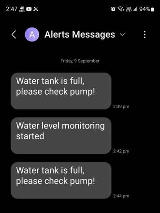
The SMS is sent when the motor starts as well as when the motor stops. You can set your own custom message in the above code.
Thats all about GSM Based Water Level Monitoring System using Arduino with SMS Notification. You can use this project for your industrial application or as a demo college project.
Video Tutorial & Guide

The advance version of this project can be sending the water tank level data to the Blynk dashboard using the GSM/GPRS network. You may refer to GSM/GPRS Water Level Monitor Project.

")


1 Comment
Is it possible to get the schematic as a file, i have noticed some fault in the pcb layout, i whis to korrekt. Regards Søren