

Overview
This is a Getting Started tutorial on Seeed XIAO RP2040 Board from Seeed Studio. Recently Seeed Studio launched the world’s smallest RP2040 Board called XIAO RP2040 which is similar to Raspberry Pi Pico. Its signature values of high performance, low cost, ease of use, and tiny thumb size make it perfect for TinyML, smart wearable devices, and IoT projects.
The board size is similar to that of XIAO BLE NRF52840 and XIAO ESP32-C3 Board. Seeed Studio XIAO RP2040 has supported Arduino, MicroPython, and CircuitPython programming.

In this guide we will learn about the overview of the XIAO RP2040 Board along with its features, capabilities, pin details, and applications. First, we will go through basic usage like the blinking of LED and using the inbuilt Neopixel LED. Then we will control the LED blinking with the help of an analog pin & potentiometer. Later we will read the sensor value from DHT11 Sensor and also display some text on OLED Screen.
Bill of Materials
Purchase the following components from the given link if you wanna get started with XIAO RP2040 Board.
| S.N. | Components | Quantity | Purchase Links |
|---|---|---|---|
| 1 | Seeed Studio RP2040 Board | 1 | Amazon | AliExpress |
| 2 | LED 5mm Any Color | 1 | Amazon | AliExpress |
| 3 | Resistor 200-ohm | 1 | Amazon | AliExpress |
| 4 | DHT11 Sensor | 1 | Amazon | AliExpress |
| 5 | 0.96" I2C OLED Display | 1 | Amazon | AliExpress |
| 6 | Jumper Wires | 10 | Amazon | AliExpress |
| 7 | Breadboard | 1 | Amazon | AliExpress |
Seeed Studio XIAO RP2040 Board

Seeed Studio XIAO RP2040 is an Arduino-compatible microcontroller featuring the Raspberry Pi Pico RP2040 chip. It carries the powerful Dual-core RP2040 processor that can flexible clock running up to 133 MHz which is a low-power microcontroller. The board also have 264KB of SRAM, and 2MB of onboard Flash memory which can provide more program to save and run. On the other hand, this little board has good performance in processing but needs less power.
The board is designed in a tiny size as small as a thumb(20×17.5mm) and can be used for wearable devices and small projects. There are 14 GPIO PINs on Seeed Studio XIAO RP2040, on which there are 11 digital pins, 4 analog pins, 11 PWM Pins,1 I2C interface, 1 UART interface, 1 SPI interface, and 1 SWD Bonding pad interface.
Seeed Studio XIAO RP2040 is friendly to the communities for its strong software compatibilities, which support Arduino, Micropython, and CircuitPython. Except for the software, flexible I/O allows it to speak to almost any external device. You can also use the Thonny editor to program as if you were using Raspberry Pi Pico. With two fast cores, plenty of on-chip RAM, and a port of TensorFlow Lite, RP2040 is a great platform for machine learning applications.

The top side of the Board has an RP2040 Chip embedded in the PCB. Like other boards, it has two buttons, one as a reset and the other as a boot button. It also has a red power LED & an on-board RGB LED. A Neopixel LED is also available on the Board which can be programmed. The Board has a type C USB interface for programming and Serial Communication.
Features
- Powerful MCU: Dual-core ARM Cortex M0+ processor, flexible clock running up to 133 MHz
- Rich on-chip resources: 264KB of SRAM, and 2MB of on-board Flash memory
- Flexible compatibility: Support Micropython/Arduino/CircuitPython
- Easy project operation: Breadboard-friendly & SMD design, no components on the back
- Small size: As small as a thumb(20×17.5mm) for wearable devices and small projects.
- Multiple interfaces: 11 digital pins, 4 analog pins, 11 PWM Pins,1 I2C interface, 1 UART interface, 1 SPI interface, 1 SWD Bonding pad interface.
Pinout
There are 14 GPIO PINs on Seeed Studio XIAO RP2040, on which there are 11 digital pins, 4 analog pins, 11 PWM Pins,1 I2C interface, 1 UART interface, 1 SPI interface, and 1 SWD Bonding pad interface.

The working voltage of the microcontroller is 3.3V. Voltage input connected to general I/O pins may cause chip damage if it is higher than 3.3V. The board can be powered via a 5V external power supply. The built-in DC-DC converter circuit able to change 5V voltage into 3.3V allows power to the device with a 5V supply via VIN-PIN and 5V-PIN.
Enter Bootloader Mode
Sometimes the Seeed Studio XIAO RP2040 port may disappear when the user programming process fails. we can solve this problem by the following operation:
- Long press the “B” button.
- Connect the Seeed Studio XIAO PR2040 to your computer.
- The computer will appear as a disk driver.
At this point, the chip enters Bootloader mode and the burn port appears again. Because the RP2040 chip has two partitions, one is the Bootloader and the other is the user program. The product will burn a bootloader code in the system memory when it leaves the factory. We can switch modes by performing the above steps.
Reset
If you want to reset the Seeed Studio XIAO RP2040, perform the following steps:
- Connect the Seeed Studio XIAO RP2040 to your computer.
- Press the “R” pins once.
Please note: The behavior of the built-in programmable Single-colour LEDs(two are blue, one is green) is reversed to the one on an Arduino. On the Seeed Studio XIAO RP2040, the pin has to be pulled low to enable it.
Getting Started with Seeed XIAO RP2040 Board
Before using XIAO RP2040 Board, we need to set up the Arduino IDE. The Arduino IDE doesn’t have a pre-installed XIAO RP2040 Board. So we need to install the board first.
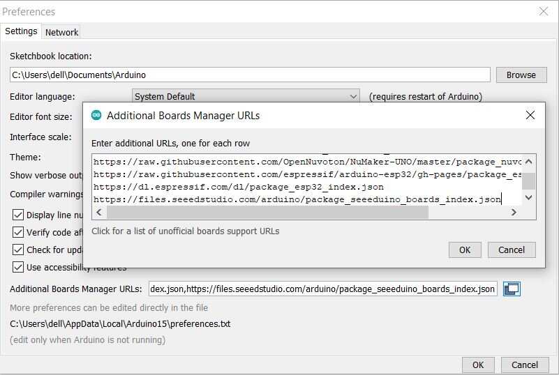
First open your Arduino IDE & Navigate to File > Preferences, and fill “Additional Boards Manager URLs” with the url below:
Navigate to Tools > Board > Boards Manager, type the keyword “RP2040” in the search box, select the latest version of and install it.

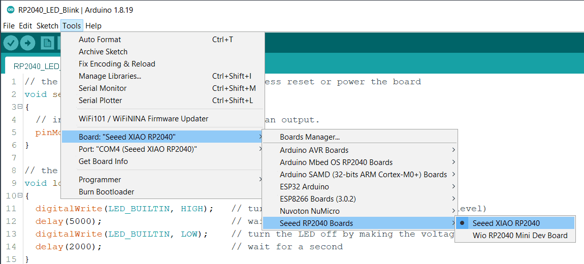
Once the board get installed, navigate to Tools > Board > Seeed RP2040 Boards and select “Seeed XIAO RP2040“.
Navigate to Tools > Port and select the serial port name of the connected Seeed XIAO RP2040.

Now your Board is ready for programming and starting the project.
Blinking of LED
The first program we are going to implement is the blinking of LED. The board has on-board RGB LED connected to Pin 25. We will use the example code to blink the LED for 1 second.
Source Code/Program
Copy the following code and upload it to the RP2040 Board.
|
1 2 3 4 5 6 7 8 9 10 11 12 13 14 15 |
// the setup function runs once when you press reset or power the board void setup() { // initialize digital pin LED_BUILTIN as an output. pinMode(LED_BUILTIN, OUTPUT); } // the loop function runs over and over again forever void loop() { digitalWrite(LED_BUILTIN, HIGH); // turn the LED on (HIGH is the voltage level) delay(5000); // wait for a second digitalWrite(LED_BUILTIN, LOW); // turn the LED off by making the voltage LOW delay(2000); // wait for a second } |
Once uploaded, you should be able to see the pin 25 Green (USER) LED on the board blinks once a second. If it does, congratulations!

This means the connection is successful and now you can explore more projects with the Seeed Studio XIAO RP2040!
Nexopixel RGB LED Usage
The Pin 11 of the XIAO RP2040 Board is the enable pin of RGB LED. You can light up the RGB LED by setting the Pin 11 high. Here we are going to make it go flash. First, we need to add a third-party library.
Open Arduino IDE, navigate to Sketch > Include Library > Manage Libraries; to search the library. Type the keyword “Adafruit_NeoPixel” library in Ardunio library Manager and install the latest version.
![]()
Source Code/Program
Now Copy the following code to Arduino IDE and click the Upload button to upload.
|
1 2 3 4 5 6 7 8 9 10 11 12 13 14 15 16 17 18 19 20 21 22 23 24 25 26 27 28 29 30 31 32 33 34 35 36 37 38 39 |
#include <Adafruit_NeoPixel.h> int Power = 11; int PIN = 12; #define NUMPIXELS 1 Adafruit_NeoPixel pixels(NUMPIXELS, PIN, NEO_GRB + NEO_KHZ800); void setup() { pixels.begin(); pinMode(Power,OUTPUT); digitalWrite(Power, HIGH); } void loop() { pixels.clear(); pixels.setPixelColor(0, pixels.Color(15, 25, 205)); delay(400); pixels.show(); pixels.clear(); pixels.setPixelColor(0, pixels.Color(103, 25, 205)); delay(400); pixels.show(); pixels.clear(); pixels.setPixelColor(0, pixels.Color(233, 242, 205)); delay(400); pixels.show(); pixels.clear(); pixels.setPixelColor(0, pixels.Color(233, 23, 23)); delay(400); pixels.show(); pixels.clear(); pixels.setPixelColor(0, pixels.Color(12, 66, 101)); delay(400); pixels.show(); delay(500); } |
Once the code is uploaded, the RGB will display the rainbow color.
![]()
Analog Pin Usgae to control LED
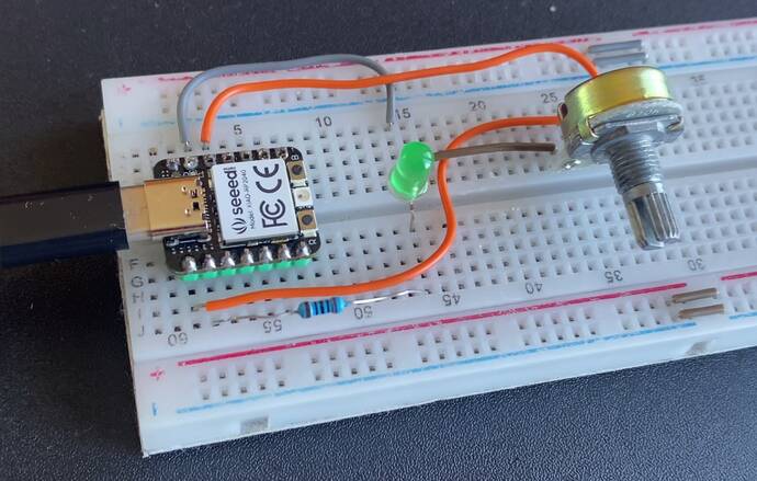
Now lets see how we can use the Analog Pin of XIAO RP2040 Board to control the LED. For this connect the potentiometer to an A0 pin and a 5mm LED to pin27 via 200-ohm resistor.

I used a breadboard for Assembly. You also design your custom PCB for this part.
Source Code/Program
Upload the following code to control the blinking interval of the LED by rotating the potentiometer knob.
|
1 2 3 4 5 6 7 8 9 10 11 12 13 14 15 16 17 18 19 20 21 22 23 24 25 |
const int sensorPin = A0; const int ledPin = 27; void setup() { // declare the ledPin as an OUTPUT: pinMode(sensorPin, INPUT); pinMode(ledPin, OUTPUT); } void loop() { // read the value from the sensor: int sensorValue = analogRead(sensorPin); // turn the ledPin on digitalWrite(ledPin, HIGH); // stop the program for <sensorValue> milliseconds: delay(sensorValue); // turn the ledPin off: digitalWrite(ledPin, LOW); // stop the program for for <sensorValue> milliseconds: delay(sensorValue); } |
DHT11 Sensor with RP2040
Now lets connect a DHT11 Sensor to XIAO RP2040 Board. Connect the VCC, GND & output pin of the DHT11 Sensor to the 3.3V, GND and pin 27 of the XIAO Board.

I used a simple breadboard connection again as shown in the image below.

Source Code/Program
The code requires DHT11 Sensor library. Open Arduino IDE, navigate to Sketch > Include Library > Manage Libraries; to search the library. Type the keyword “DHT11” library in Ardunio library Manager and install the latest version.
Copy the following code to Arduino IDE and click the Upload button to upload.
|
1 2 3 4 5 6 7 8 9 10 11 12 13 14 15 16 17 18 19 20 21 22 23 24 25 26 27 28 29 30 31 32 33 34 |
#include "DHT.h" #define DHTPIN 27 // Digital pin connected to the DHT sensor #define DHTTYPE DHT11 // DHT 11 DHT dht(DHTPIN, DHTTYPE); void setup() { Serial.begin(115200); Serial.println(F("DHTxx test!")); dht.begin(); delay(2000); } void loop() { float h = dht.readHumidity(); float t = dht.readTemperature(); // Check if any reads failed and exit early (to try again). if (isnan(h) || isnan(t)) { Serial.println(F("Failed to read from DHT sensor!")); return; } Serial.print(F("Humidity: ")); Serial.print(h); Serial.println("%"); Serial.print(F("Temperature: ")); Serial.print(t); Serial.println(F("°C ")); Serial.println(""); delay(2000); } |
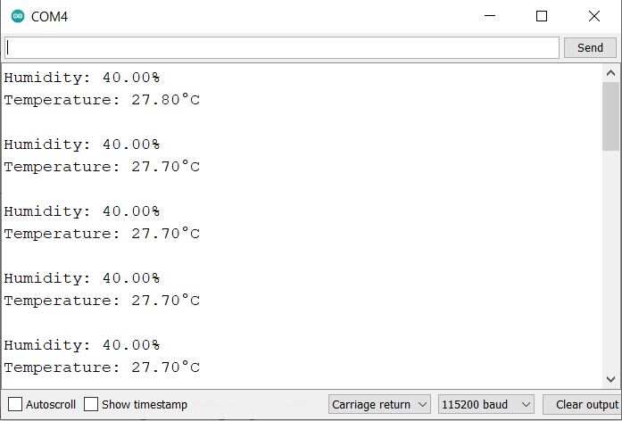
After the code is uploaded, open the Serial Monitor. You can see the humidity and temperature data on Serial Monitor.
OLED Display with RP2040
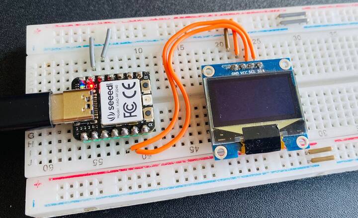
Here we are going to connect the XIAO RP2040 Board with OLED Display 0.96″ through I2C pins and display “Hello world”.

We are going use PIN 5 as the SCL pin and PIN 4 as the SDA pin.
Source Code/Program
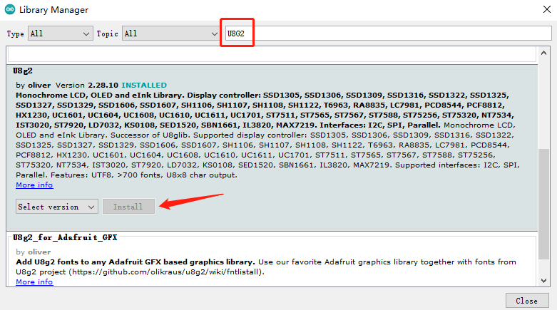
Open Arduino IDE, navigate to Sketch > Include Library > Manage Libraries to search the library. Type the keyword “U8G2” library in Ardunio library Manager and install the lastest version.
Copy the following code to Arduino IDE and click the Upload button to upload.
|
1 2 3 4 5 6 7 8 9 10 11 12 13 14 15 16 17 18 19 20 21 22 23 24 25 |
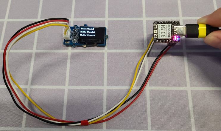
#include <Arduino.h> #include <U8g2lib.h> #ifdef U8X8_HAVE_HW_SPI #include <SPI.h> #endif #ifdef U8X8_HAVE_HW_I2C #include <Wire.h> #endif U8G2_SSD1306_128X64_NONAME_F_SW_I2C u8g2(U8G2_R0, /* clock=*/ SCL, /* data=*/ SDA, /* reset=*/ U8X8_PIN_NONE); void setup(void) { u8g2.begin(); } void loop(void) { u8g2.clearBuffer(); // clear the internal memory u8g2.setFont(u8g2_font_ncenB08_tr); // choose a suitable font u8g2.drawStr(0,10,"Hello Wrold!"); // write something to the internal memory u8g2.drawStr(0,30,"Hello Werold!"); u8g2.drawStr(0,50,"Hello Wrrrold!"); u8g2.sendBuffer(); // transfer internal memory to the display delay(1000); } |
Results are shown as:
Video Tutorial & Guide


1 Comment
Any experience with the Xiao and Modbus, using the Max3485 chip and MdbusRtu library