

Overview
This is a Getting Started tutorial on Seeed XIAO ESP32-C3 Board from Seeed Studio. Recently Seeed Studio launched the world’s smallest ESP32 Board called XIAO ESP32 C3. This is an IoT mini-development board based on the Espressif ESP32-C3 WiFi/Bluetooth dual-mode chip.
The main difference between the ESP32 & ESP32-C3 Board is the processor and BLE version. The ESP32 has Tensilica Xtensa LX6 32-bit Dual-Core processor operating at a frequency of 160/240Mhz whereas the ESP32-C3 Board has RISC-V 32-bit Single-Core processing running at a clock frequency of 160 MHz. While comparing the BLE part, ESP32 has 4.2 BR/EDR + BLE and ESP32-C3 has 5.0 + BLE which is upgraded.

In this guide we will learn about the overview of the XIAO ESP32-C3 Board along with its features, capabilities, pin details, and applications. First, we will go through basic usage like the blinking of LED and reading the DHT11 Sensor Data. Under the WiFi usage category, we will create a simple web server where data of a sensor can be viewed on a Webserver. Finally, under the BLE usage part, we will scan the Bluetooth devices nearby using the Bluetooth feature of this board.
You can also check some other XIAO Series board tutorials:
1. Getting Started with Seeed XIAO RP2040 with Projects
Bill of Materials
Purchase the following components from the given link if you wanna get started with XIAO ESP32-C3 Board.
| S.N. | Components | Quantity | Purchase Links |
|---|---|---|---|
| 1 | Seeed Studio XIAO ESP32C3 | 1 | Amazon | AliExpress |
| 2 | LED 5mm Any Color | 1 | Amazon | AliExpress |
| 3 | Resistor 200-ohm | 1 | Amazon | AliExpress |
| 4 | DHT11 Sensor | 1 | Amazon | AliExpress |
| 5 | Jumper Wires | 10 | Amazon | AliExpress |
| 6 | Breadboard | 1 | Amazon | AliExpress |
Seeed Studio XIAO ESP32-C3
The Seeed Studio XIAO ESP32-C3 carries a complete Wi-Fi system along with Bluetooth Low Energy function. With its exquisite design and WiFi+BLE ability, it’s perfect for various IoT controlling scenarios and complex carriable applications.

ESP32-C3 is a 32-bit RISC-V CPU, which includes an FPU (Floating Point Unit) for 32-bit single-precision arithmetic with powerful computing power. It has excellent radio frequency performance, supporting IEEE 802.11 b/g/n WiFi, and Bluetooth 5 (LE) protocols. This board comes included with an external antenna to increase the signal strength for your wireless applications. It also has a small and exquisite form factor combined with a single-sided surface-mountable design.
Features of Seeed Studio XIAO ESP32-C3
- Powerful CPU: ESP32-C3, 32bit RISC-V singlecore processor that operates at up to 160 MHz
- Complete WiFi subsystem: Complies with IEEE 802.11b/g/n protocol and supports Station mode, SoftAP mode, SoftAP + Station mode, and promiscuous mode
- Bluetooth LE subsystem: Supports features of Bluetooth 5 and Bluetooth mesh
- Ultra-Low Power: Deep sleep power consumption is about 43μA
- Better RF performance: External RF antenna included
- Battery charging chip: Supports lithium battery charge and discharge management
- Rich on-chip resources: 400KB of SRAM, and 4MB of on-board flash memory
- Ultra-small size: As small as a thumb(20×17.5mm) XIAO series classic form-factor for wearable devices and small projects
- Reliable security features: Cryptographic hardware accelerators that support AES-128/256, Hash, RSA, HMAC, digital signature, and secure boot
- Rich interfaces: 1xI2C, 1xSPI, 1xI2S, 2xUART, 11xGPIO(PWM), 4xADC, 1xJTAG bonding pad interface
- Single-sided components, surface mounting design
Front & Back Components

The front side of the board has an ESP32-C3 chip packed on an SMD surface of the PCB. Like other ESP32 boards, this board also has a boot and reset button. It also features a charge LED which indicates battery charging while charging the battery. It supports a USB-Type C interface for UART/Serial Communication. The board has a UFL connector for an external antenna to increase the signal strength for any wireless applications.

On the backside of the board, there is a JTAG interface for providing access to debug/emulation functions. A battery connector port is there to connect a 3.7V Lithium-Ion Battery for portable applications. A thermal pad is also provided at the backside of the board which can be used as a cooling system while there is excessive use of the CPU which may produce heat.
Pinout of Seeed XIAO ESP32-C3
The Seeed XIAO ESP32-C3 Board has a total number of 14 pins. Out of 14 pins, it has 11 digital pins (D0-D10) and 4 analog pins (A0-A3). These pins also support I2C, SPI, I2S, and a pair of UART protocols.

The board has 5V, 3.3V & GND as power pin. The USB pin is 5V output. The pin from the board is used as a voltage input but must have some sort of diode (Schottky, signal, power) between the external power source and this pin with the anode to the battery, cathode to 5V pin. The board also outputs 3.3V regulated output from the onboard regulator & can draw current up to 700mA.
Antenna of XIAO ESP32-C3
The XIAO ESP32-C3 has a UFL connector for attaching an antenna. The external antenna of 2.4GHz frequency can be used for WiFi & BLE applications.
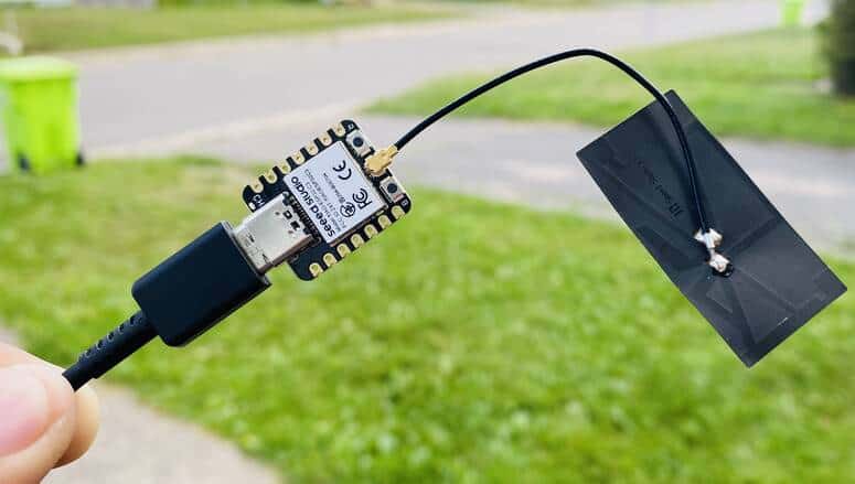
Therefore connect an external antenna to increase the signal strength.
Getting Started with Seeed XIAO ESP32-C3 Board
Before using ESP32-C3 Board, we need to setup the Arduino IDE. The Arduino IDE doesn’t have pre-installed ESP32-C3 Board. So we need to install the board first.
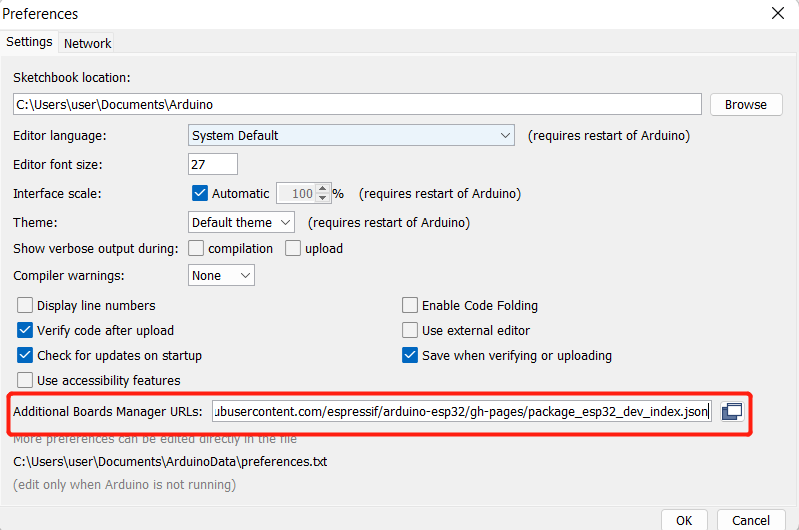
First open your Arduino IDE & Navigate to File > Preferences, and fill “Additional Boards Manager URLs” with the url below:
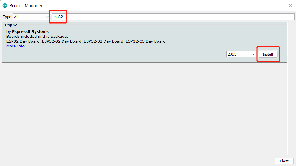
Navigate to Tools > Board > Boards Manager, type the keyword “esp32” in the search box, select the latest version of and install it.
Once the board get installed, navigate to Tools > Board > ESP32 Arduino and select “XIAO_ESP32C3“. The list of boards is a little longer and you need to roll to the bottom to reach it.

Navigate to Tools > Port and select the serial port name of the connected XIAO ESP32C3.
Now your XIAO ESP32-C3 Board is ready for programming and starting the project.
Blinking of LED
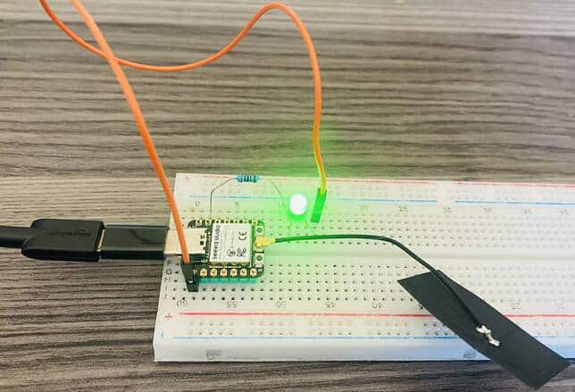
The first program we are going to implement is the blinking of LED. Here is the connection diagram for this project.

Connect the LED positive pin to GPIO2 and the LED negative pin to GND via a 200-ohm resistor. You can use a breadboard to assemble the circuit.

Source Code/Program
Copy the following code and upload it to the ESP32-C3 Board.
|
1 2 3 4 5 6 7 8 9 10 11 12 13 14 15 |
#define LED_BUILTIN 2 // the setup function runs once when you press reset or power the board void setup() { // initialize digital pin LED_BUILTIN as an output. pinMode(LED_BUILTIN, OUTPUT); } // the loop function runs over and over again forever void loop() { digitalWrite(LED_BUILTIN, HIGH); // turn the LED on (HIGH is the voltage level) delay(1000); // wait for a second digitalWrite(LED_BUILTIN, LOW); // turn the LED off by making the voltage LOW delay(1000); // wait for a second } |
After uploading the code, the LED will turn ON/OFF after an interval of 1 second.
Reading DHT11 Sensor Data
The second program we are going to implement is the reading DHT11 Humidity & Temperature sensor data. Here is the connection diagram for this project.

Connect the DHT11 VCC, GND & output pin to 3.3V, GND & GPIO5 of XIAO ESP32-C3 board. You can use a breadboard to assemble the circuit.

Source Code/Program
The code requires DHT11 Sensor Library for compilation. Therefore first download and install the library using library manager. Then copy the following code and upload it to the ESP32-C3 Board.
|
1 2 3 4 5 6 7 8 9 10 11 12 13 14 15 16 17 18 19 20 21 22 23 24 25 26 27 28 29 30 31 32 33 34 |
#include "DHT.h" #define DHTPIN 5 // Digital pin connected to the DHT sensor #define DHTTYPE DHT11 // DHT 11 DHT dht(DHTPIN, DHTTYPE); void setup() { Serial.begin(9600); Serial.println(F("DHTxx test!")); dht.begin(); delay(2000); } void loop() { float h = dht.readHumidity(); float t = dht.readTemperature(); // Check if any reads failed and exit early (to try again). if (isnan(h) || isnan(t)) { Serial.println(F("Failed to read from DHT sensor!")); return; } Serial.print(F("Humidity: ")); Serial.print(h); Serial.println("%"); Serial.print(F("Temperature: ")); Serial.print(t); Serial.println(F("°C ")); Serial.println(""); delay(2000); } |
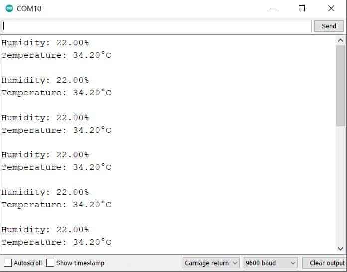
After uploading the code, open the Serial Monitor. The Serial Monitor will display the Humidity & Temperature Data.
WiFi Usage on XIAO ESP32-C3 Board
Now let us see how we can use the WiFi feature of the Seeed XIAO ESP32-C3 Board. For this we will use the same hardware setup as above. Instead of displaying DHT11 Sensor data on Serial Monitor, we will display the temperature & humidity value on a Webserver.
The ESP32-C3 Web server can be used to process and manage HTTP requests and responses from the web page.
Source Code/Program
Here is a complete code for ESP32 DHT11 Webserver. The code requires DHT11 library again.
|
1 2 |
const char* ssid = "************"; // Enter SSID here const char* password = "************"; //Enter Password here |
In the above line change the WiFi SSID & password so that the ESP32 can connect to the WiFi network using the given credentials.
|
1 2 3 4 5 6 7 8 9 10 11 12 13 14 15 16 17 18 19 20 21 22 23 24 25 26 27 28 29 30 31 32 33 34 35 36 37 38 39 40 41 42 43 44 45 46 47 48 49 50 51 52 53 54 55 56 57 58 59 60 61 62 63 64 65 66 67 68 69 70 71 72 73 74 75 76 77 78 79 80 81 82 83 84 85 86 87 88 89 90 91 92 93 94 95 |
#include <WiFi.h> #include <WebServer.h> #include "DHT.h" #define DHTTYPE DHT11 // DHT 11 /*Put your SSID & Password*/ const char* ssid = "************"; // Enter SSID here const char* password = "************"; //Enter Password here WebServer server(80); // DHT Sensor uint8_t DHTPin = 5; // Initialize DHT sensor. DHT dht(DHTPin, DHTTYPE); float Temperature; float Humidity; void setup() { Serial.begin(115200); delay(100); pinMode(DHTPin, INPUT); dht.begin(); Serial.println("Connecting to "); Serial.println(ssid); //connect to your local wi-fi network WiFi.begin(ssid, password); //check wi-fi is connected to wi-fi network while (WiFi.status() != WL_CONNECTED) { delay(1000); Serial.print("."); } Serial.println(""); Serial.println("WiFi connected..!"); Serial.print("Got IP: "); Serial.println(WiFi.localIP()); server.on("/", handle_OnConnect); server.onNotFound(handle_NotFound); server.begin(); Serial.println("HTTP server started"); } void loop() { server.handleClient(); } void handle_OnConnect() { Temperature = dht.readTemperature(); // Gets the values of the temperature Humidity = dht.readHumidity(); // Gets the values of the humidity server.send(200, "text/html", SendHTML(Temperature,Humidity)); } void handle_NotFound(){ server.send(404, "text/plain", "Not found"); } String SendHTML(float Temperaturestat,float Humiditystat) { String ptr = "<!DOCTYPE html> <html>\n"; ptr +="<head><meta name=\"viewport\" content=\"width=device-width, initial-scale=1.0, user-scalable=no\">\n"; ptr +="<title>ESP32 Webserver</title>\n"; ptr +="<style>html { font-family: Helvetica; display: inline-block; margin: 0px auto; text-align: center;}\n"; ptr +="body{margin-top: 50px;} h1 {color: #444444;margin: 50px auto 30px;}\n"; ptr +="p {font-size: 24px;color: #444444;margin-bottom: 10px;}\n"; ptr +="</style>\n"; ptr +="</head>\n"; ptr +="<body>\n"; ptr +="<div id=\"webpage\">\n"; ptr +="<h1>ESP32 Webserver</h1>\n"; ptr +="<p>Temperature: "; ptr +=(int)Temperaturestat; ptr +=" C</p>"; ptr +="<p>Humidity: "; ptr +=(int)Humiditystat; ptr +="%</p>"; ptr +="</div>\n"; ptr +="</body>\n"; ptr +="</html>\n"; return ptr; } |
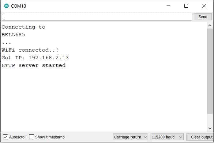
After uploading the code, open the Serial Monitor. The Serial Monitor will have the IP Address of ESP32 after a successful connection with the WiFi network.
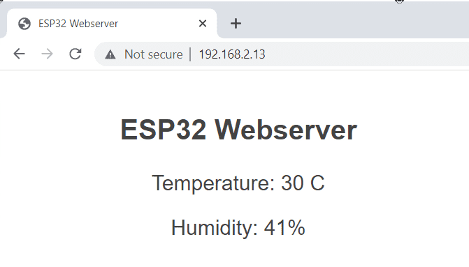
Open any web browser either on PC or a mobile phone and enter the above IP Address and hit enter. A web page will appear showing the Humidity and Temperature value on a Webpage.
Bluetooth (BLE) Usage on XIAO ESP32-C3 Board
In this example, we are going to use XIAO ESP32-C3 to scan available Bluetooth devices around it.
In case of ESP32-C3 BLE, the data during communication is organized using a profile referred to as GATT (Generic Attributes). There are essentially two protocols that are important in communication between two BLE devices; GAP and GATT. GAP is an acronym for the Generic Access Profile, and it controls connections and advertising (Making a device visible and open for connection) in Bluetooth. GATT is an acronym for the Generic Attribute Profile, and it defines how two Bluetooth Low Energy devices, transfer data back and forth between each other, using concepts called Services and Characteristics.
Source Code/Program
Copy the following code and paste it into Arduino IDE. Then you can upload it to the ESP32-C3 Board.
|
1 2 3 4 5 6 7 8 9 10 11 12 13 14 15 16 17 18 19 20 21 22 23 24 25 26 27 28 29 30 31 32 33 34 35 |
#include <BLEDevice.h> #include <BLEUtils.h> #include <BLEScan.h> #include <BLEAdvertisedDevice.h> int scanTime = 5; //In seconds BLEScan* pBLEScan; class MyAdvertisedDeviceCallbacks: public BLEAdvertisedDeviceCallbacks { void onResult(BLEAdvertisedDevice advertisedDevice) { Serial.printf("Advertised Device: %s \n", advertisedDevice.toString().c_str()); } }; void setup() { Serial.begin(115200); Serial.println("Scanning..."); BLEDevice::init(""); pBLEScan = BLEDevice::getScan(); //create new scan pBLEScan->setAdvertisedDeviceCallbacks(new MyAdvertisedDeviceCallbacks()); pBLEScan->setActiveScan(true); //active scan uses more power, but get results faster pBLEScan->setInterval(100); pBLEScan->setWindow(99); // less or equal setInterval value } void loop() { // put your main code here, to run repeatedly: BLEScanResults foundDevices = pBLEScan->start(scanTime, false); Serial.print("Devices found: "); Serial.println(foundDevices.getCount()); Serial.println("Scan done!"); pBLEScan->clearResults(); // delete results fromBLEScan buffer to release memory delay(2000); } |
Upload the codes and open the Serial Monitor to start scanning for Bluetooth devices. The Serial monitor will display the number of available devices nearby.

This is how you can use Seeed XIAO ESP32-C3 Board for IoT projects and other applications.
Video Tutorial & Guide


6 Comments
Just received a few of these. Very slick product.
Noted that the normal boot loader data dump to the serial port on power up and reset is disabled. Also noted that no crash information is sent to the serial port.
How can I turn off quiet boot mode and allow crash info dump?
Using Arduino IDE 1.8.19 with arduino-esp32 core v2.0.5. USB CDC on Boot is Enabled in the IDE.
I just receive two pieces of ESP32C3. Happy :-). I install earlier necessary software for ESP32. But when I connect ESP on my computer (Win7) ESP was not recognized. Is there a driver for that module?
Mladen
Hi Mladen. You have to hold boot switch and then plug USB cable in..
Unfortunately I did not manage to control a servo. The ESP32Servo library does not work. I am very grateful for any help
What is this trying to actually say? What is a “USB pin”? Can I give 5V to the 5V pin?
The USB pin is 5V output. The pin from the board is used as a voltage input but must have some sort of diode (Schottky, signal, power) between the external power source and this pin with the anode to the battery, cathode to 5V pin.
Yes you can give 5v to 5v pin